A miniature functional analogue of a decatron for a replica of Harwell Dekatron Computer and more.

In developing this functional analogue of the decatron, the author pursued two goals: to take part in the same design competition on boards of one square inch, and also to use many such modules in the WITCH-E project to recreate Harwell Dekatron Computer , also known as WITCH (Wolverhampton Instrument for Teaching Computing from Harwell) on modern components. But you can collect on such "decatrons" and simpler schemes.
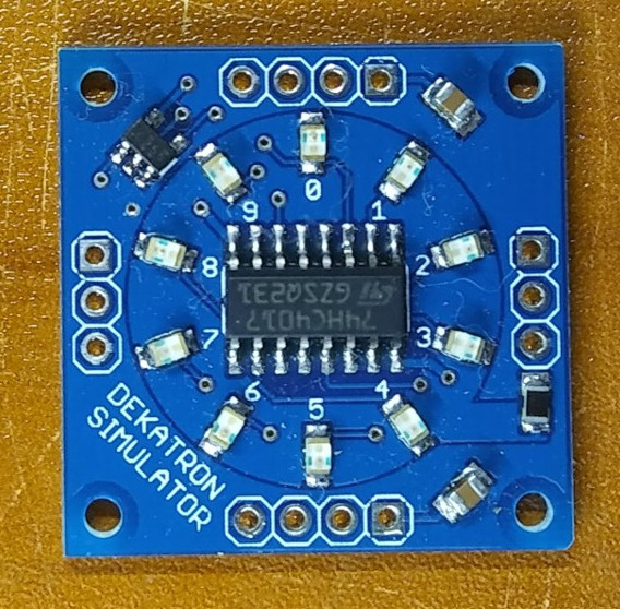
The 74HC4017 chip used in the device, as its name implies, is similar to the 4017B (K561IE8) for its intended purpose, but differs from it in increased speed and a narrower range of supply voltages (2 - 6 V). In addition to it, 10 LEDs of a standard size of 0805, 2 resistors on 470 Ohm of a standard size of 0603 and two condensers on 100 nF of the same standard size are necessary. The module interacts with external circuits using two groups of five pads each, the four lines on which — VCC, ENABLE, RESET and GND — are duplicated. The CLK-OUT line is brought to the remaining platform of one group, the other - CLK-IN. Thus, a multi-digit decimal counter can be obtained by joining several modules and sending pulses to the one located on the right. Power and common wire can be connected from either side. To contact pads, you can solder pins for installation in breadboard (as on ) or connectors for assembling multi-digit counters without soldering. The scheme itself is the same as in many other functional analogs of the decatron:

Files (under CC-BY-NC 4.0): scheme in PDF , archive with a project in EAGLE , archive with “gerberas” .
')
At the beginning, the author wanted to use rather bulky modules in the WITCH-E project, consisting of a 74HC160 counter, a 74HC4511 decoder, eight resistors and a seven-segment indicator.

But they turned out to be inconvenient and not at all like the decatrons, which, as we know, look like this (and this is what the device is shown there):
Therefore, the author designed three versions of boards on the 74HC4017 with LEDs arranged in a circle. At the first, the LEDs and the microcircuit are located on different sides of the board:

Here is a three-digit counter on such modules that counts the impulses coming from the generator:
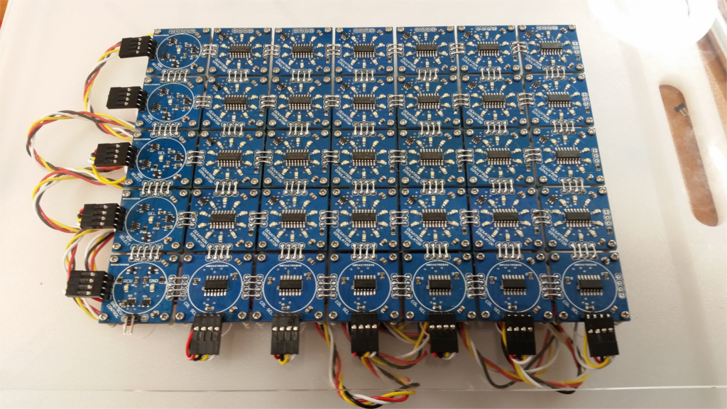
Turning over the boards when assembling them in large quantities turned out to be inconvenient, therefore, in the second version, the microcircuit and the LEDs are located on the same side.
This is how the fragment of the future WITCH-E computer looks on the boards of the second variant together with the row and column selection boards:
Finally, the author combined contact pads for external circuits into two groups instead of four, while simultaneously reducing the total number of pads. This is how the third version of the board turned out:
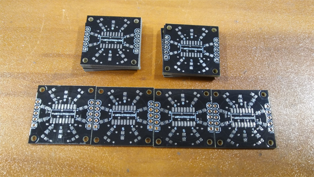
It turned out to be compact enough to fit into the requirements of the "square-inch" competition. And by soldering thin conductors directly to the pins of the microcircuit, you can reduce the conversion factor without changing the board topology, which is necessary when using such modules in hours.
Source: https://habr.com/ru/post/447474/
All Articles