Features rendering in the game Metro: Exodus c raytracing

Foreword
After the release of the last game from the Metro series, I spent a few hours studying its internal work and decided to share what might seem interesting from a technological point of view. I will not conduct a detailed analysis or study the disassembled shader code, but will show the high-level decisions made by the developers in the process of creating the game.
At the moment, the developers have not yet talked about the rendering techniques used in the game. The only official source of information is the GDC report , which cannot be found anywhere else on the Internet. And it is annoying, because the game works on a very interesting own engine, which evolved from the previous games of the Metro series. This is one of the first games that use DXR .
Note: this article is not a complete description and I will come back to it if I find something worth adding. Maybe I missed something, because some aspects appear only in the next stages of the game, or I just looked at the details.
')
The first steps
It took me several days to search for an environment capable of working with this game. Having tested several versions of RenderDoc and PIX, I stopped to study the results of ray tracing using Nvidia NSight. I wanted to study rendering without raytracing functions, but NSight allowed me to explore the details of this function, so I decided to leave it turned on. For the rest of the rendering, the PIX was quite appropriate. Screenshots are made using both applications.
NSight has one drawback - it does not support saving capture to a file, so I could not go back to the frames I studied.
At the very beginning of my work, I also encountered another problem that was not related to frame debugging applications: the ray tracing functions required installing the latest Windows update, but the game made it possible to enable them in options without installing the update. In this case, the inclusion of functions led to the failure of the game at launch. GeForce Experience also did not report the need for the correct version of Windows to enable these features. This problem needs to be addressed on both sides.
For the sake of completeness, I made captures from a game launched with the highest possible parameters, but without DLSS.
Frame analysis
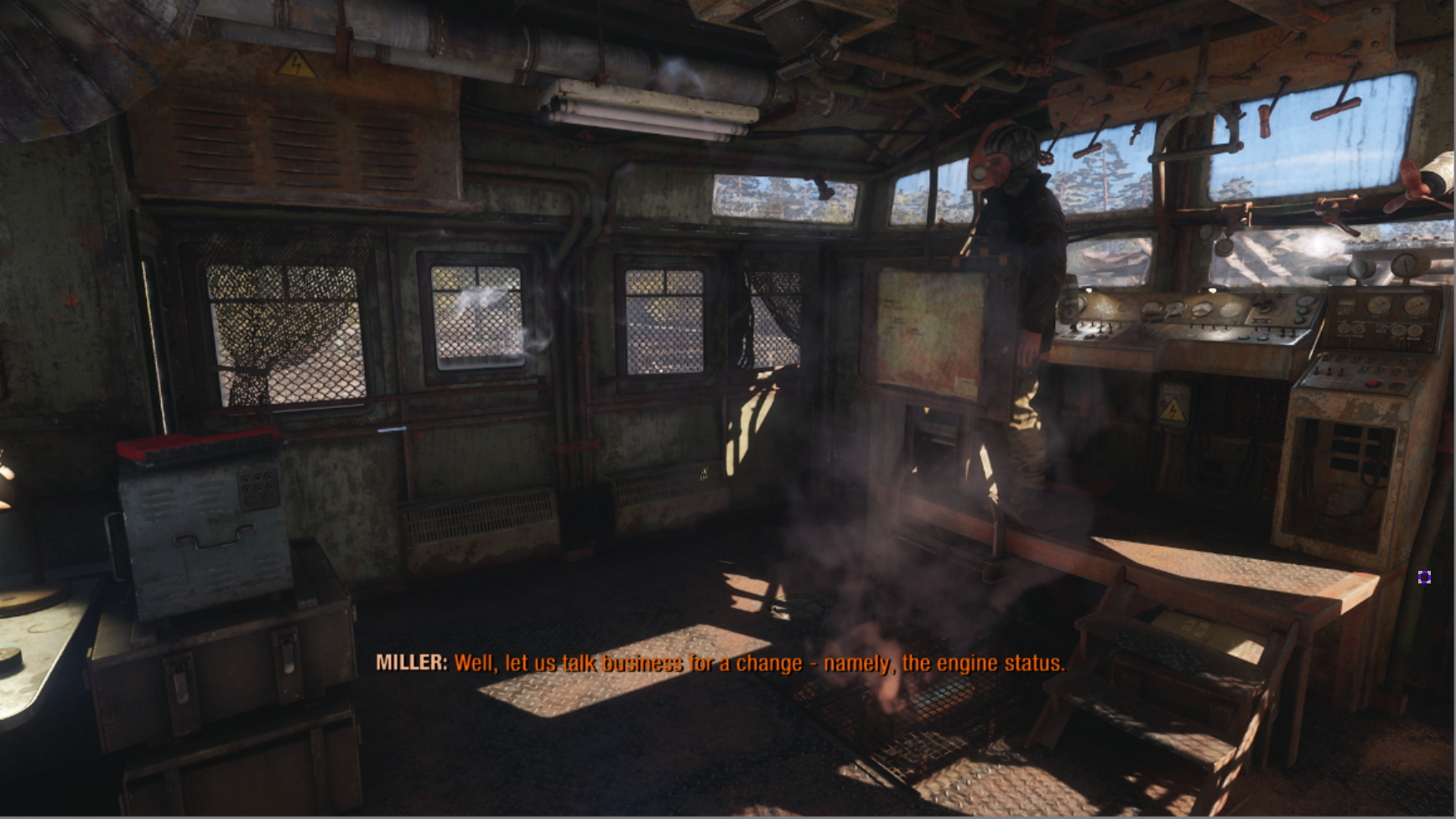
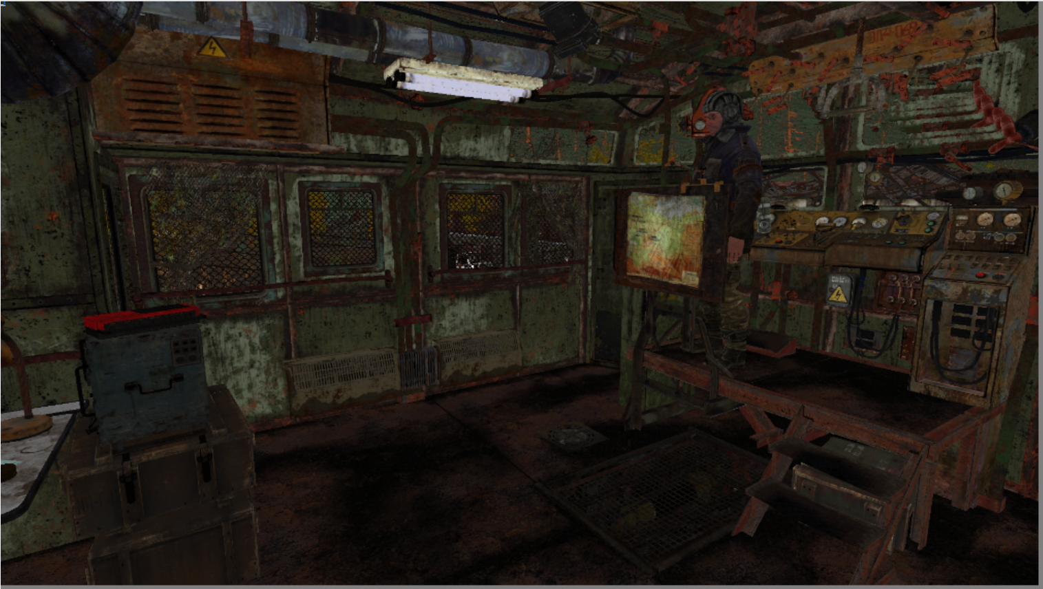
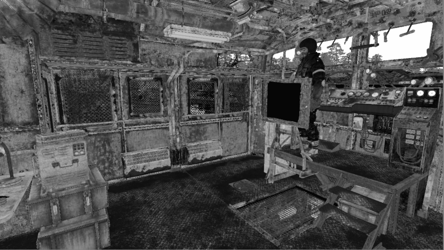
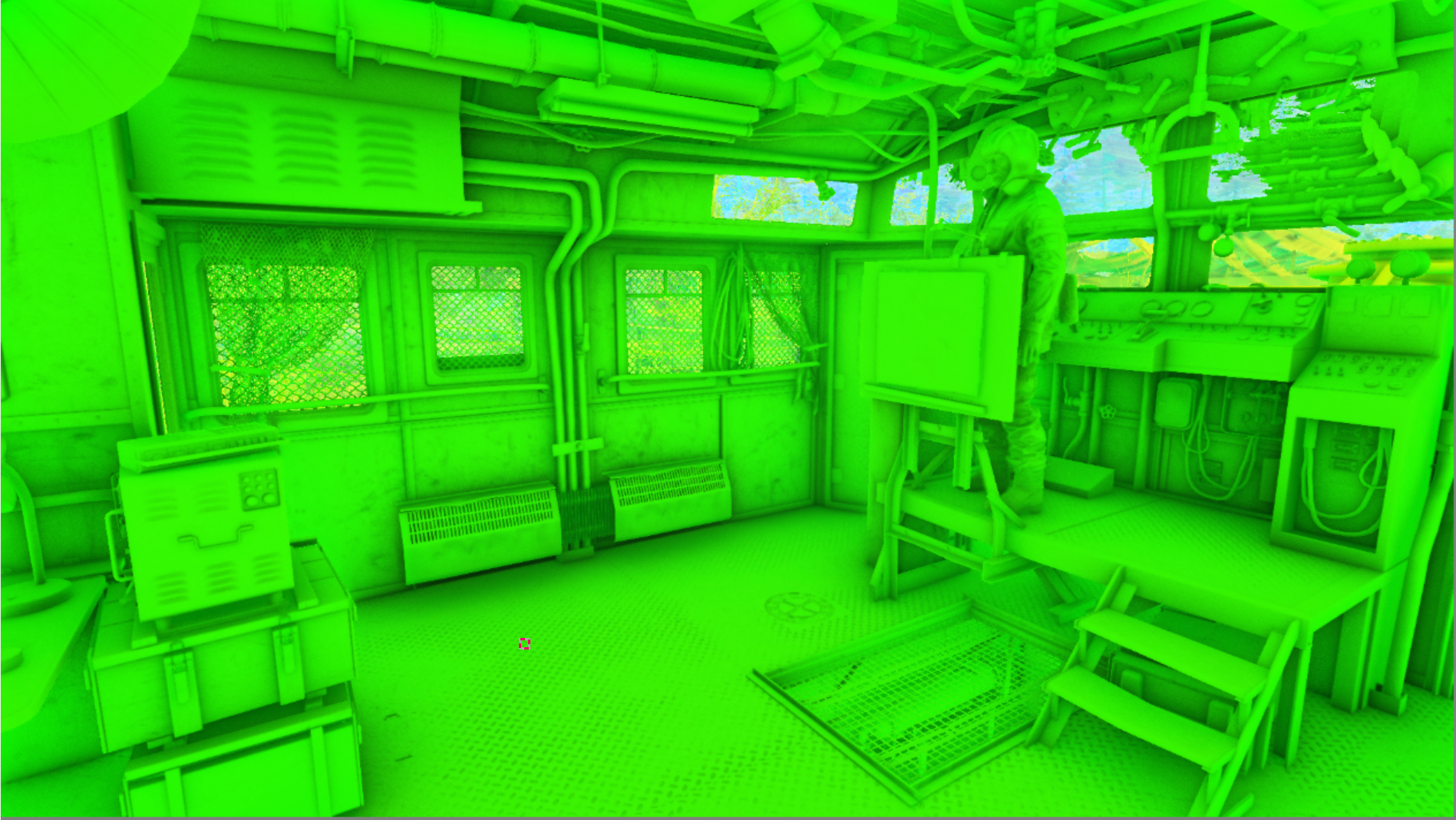
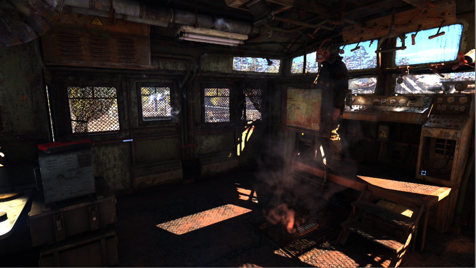
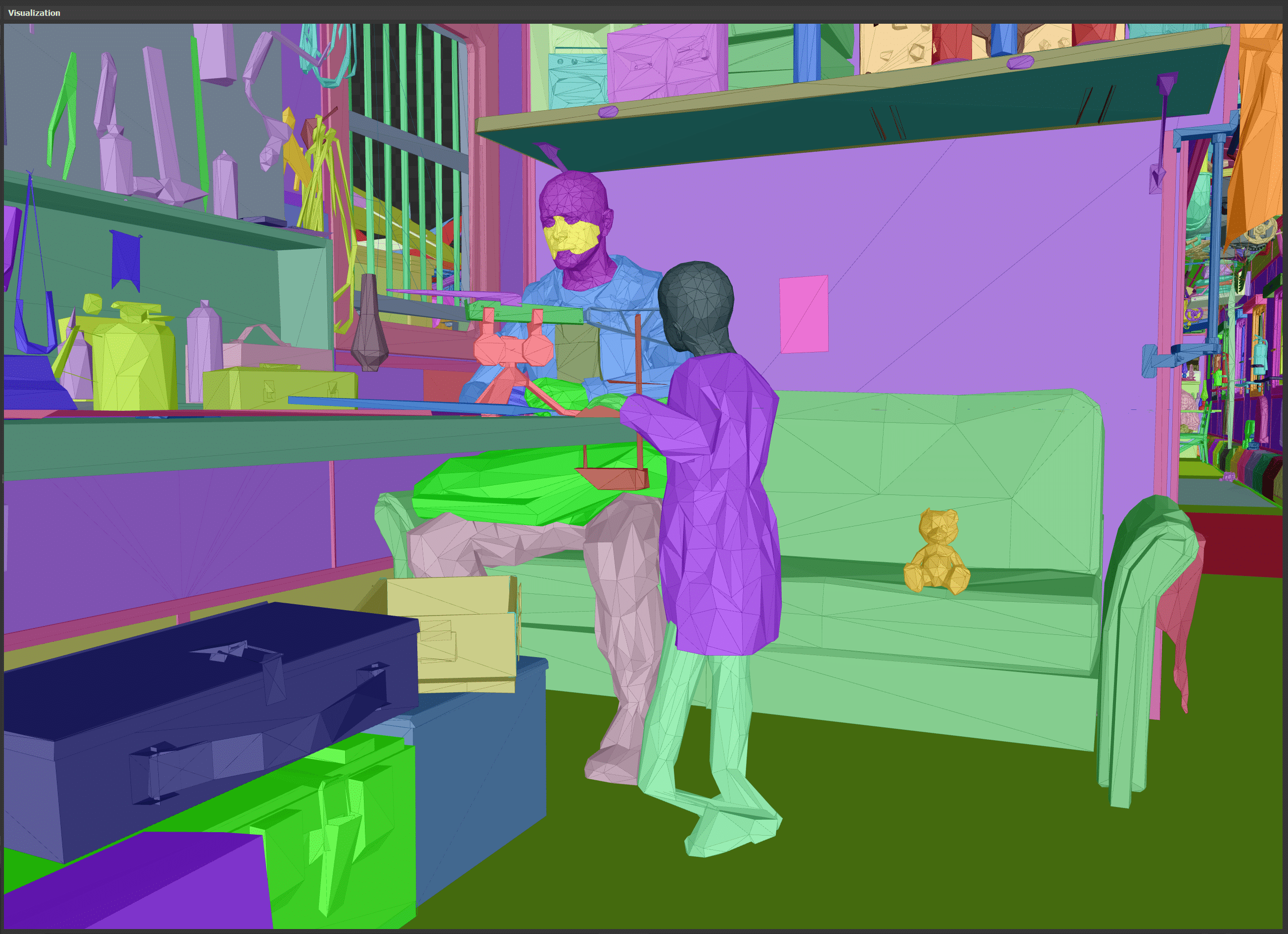
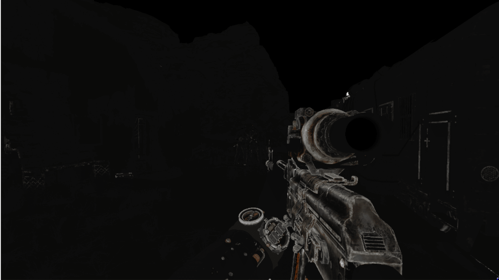
Ready frame
A brief analysis of the rendering demonstrates a fairly standard set of functions, with the exception of global illumination performed by ray-traced ray (GI).
Before rendering the image, the scale of the previous frame is reduced in the compute queue and the average brightness is calculated.
The graphic queue begins with the rendering of distortion particles (droplets on the camera), which are applied at the post-processing stage. Then a quick preview of the depths creates a portion of the depths in front of the Gbuffer; it seems that it renders only relief.
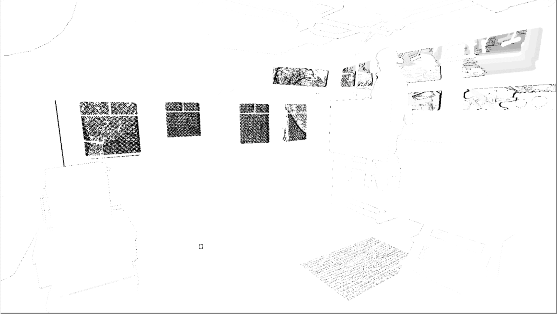
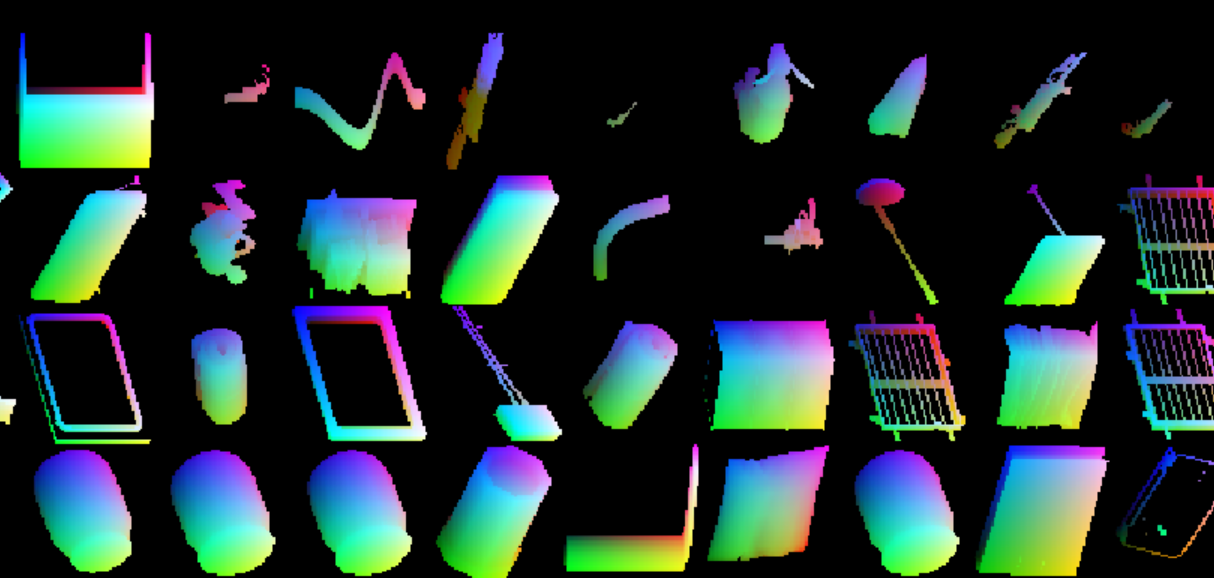
The GBuffer pass fills the 4 render target as shown below, and also completes the depth buffer filling.
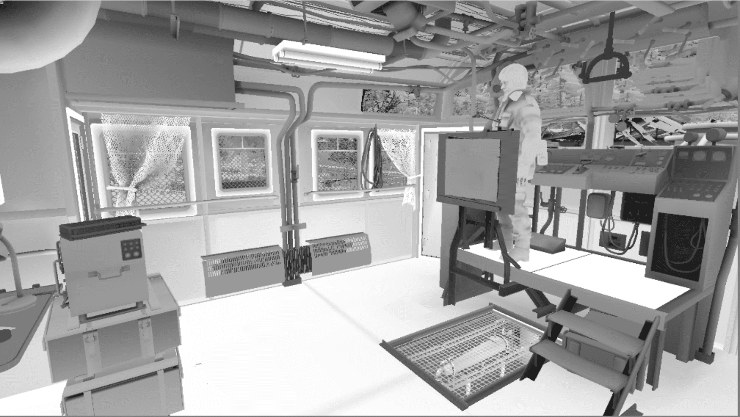
1. Target in RGBA8 format with albedo and, possibly, Ambient Occlusion in the alpha channel; on some surfaces it looks very dark.
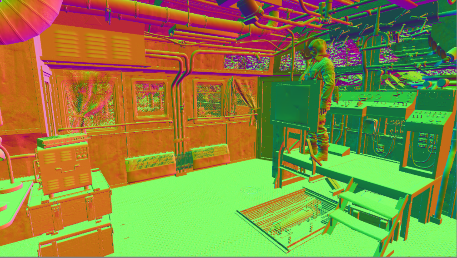
2. Target in RGB10A2 format with normals and, possibly, a subsurface scattering mask in the alpha channel.
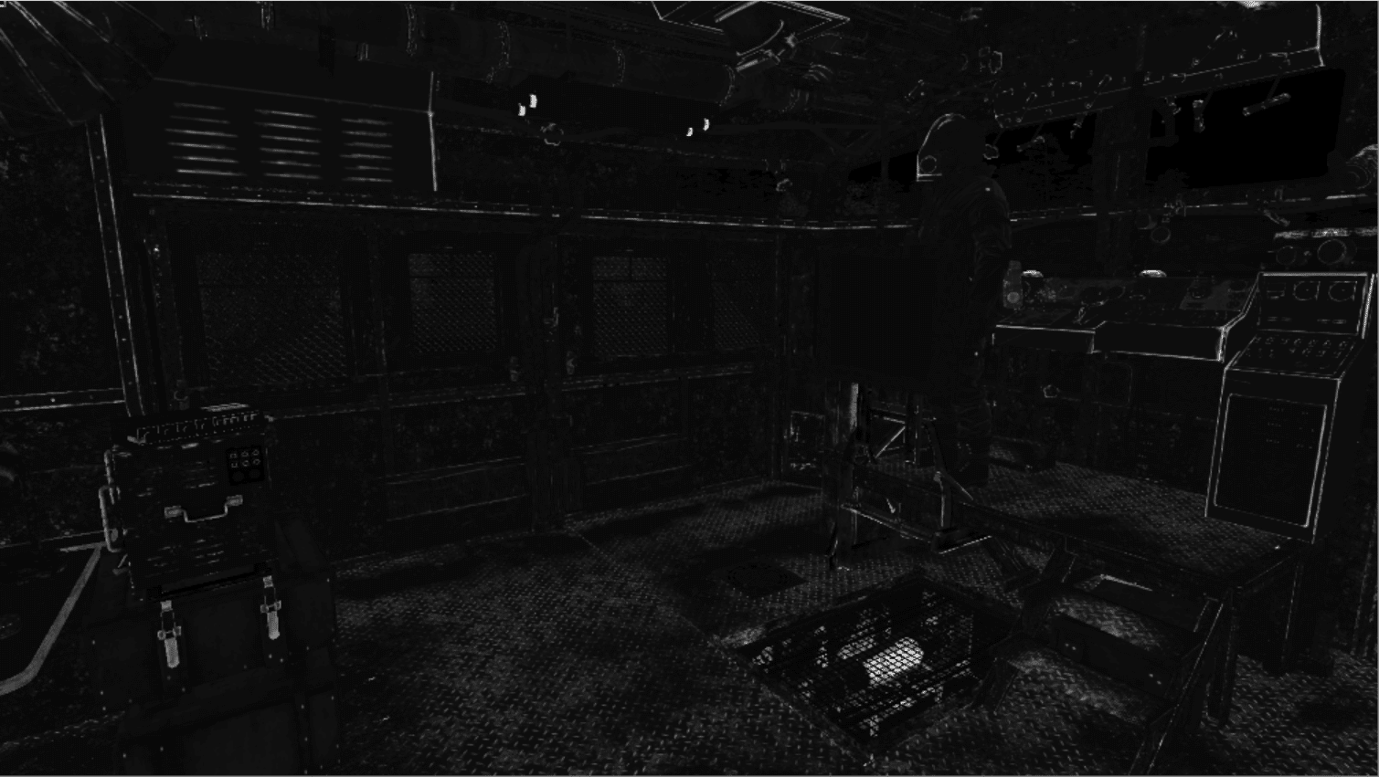
3. Target in RGBA8 format with different material parameters, probably metalness and roughness in the alpha channel. Curiously, the RGB channels in this case contain exactly the same data.
4. Target in RG16F format with 2D motion vectors.
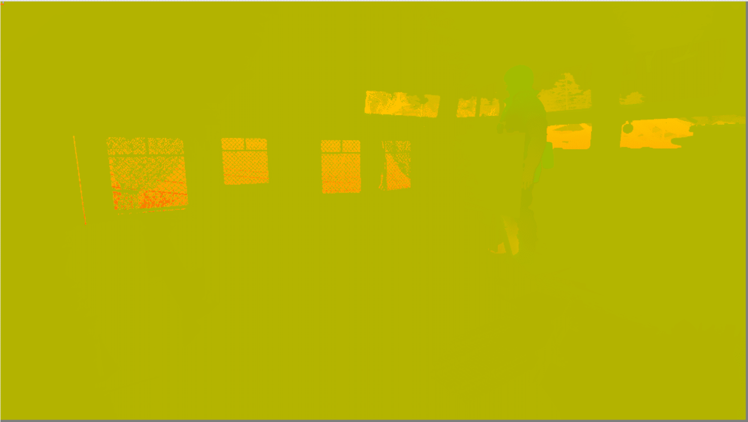
After the depths are completely filled, a linear depth buffer is built and its scale decreases. All this is done in the compute queue. In the same queue, the buffer is filled with something similar to directional lighting without the use of shadows.
In the graphical queue, the GPU is engaged in tracing the rays of global illumination, but I will discuss this in more detail below.
In the compute queue, ambient occlusion, reflections, and something similar to edge detection are calculated.
In the graphics queue, a four-casted shadow map is rendered into a 32-bit depth map of 6k * 6k. More on this below. After the completion of the directed shadows map, the resolution of the third cascade for unknown reasons decreases to 768 * 768.
In the middle of the shadow rendering process there is a curious point: impostor atlas is supplemented with some objects before rendering local shadows from lighting (what impostors are, you can read here ). Both the impostor buffers and the shadows buffers of the local lighting are also textures of size 6k * 6k.
After all the shadows are complete, the illumination calculation starts. This part of the rendering is rather incomprehensible, because here there are a lot of drawings that perform some mysterious actions, and therefore require additional study.
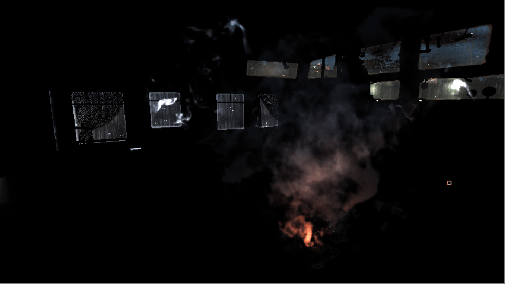
Rendering of the scene is completed with frontally lit objects (eyes, particles). Visual effects are rendered into a half-resolution buffer, after which they are composited with opaque objects using an increase in scale.
The final picture is achieved by tone correction and bloom calculation (decrease, and then increase the resolution of the frame with tone correction). Finally, the UI is rendered into a separate buffer and, with bloom, compositing is superimposed on top of the scene.
I did not find the part in which smoothing is performed, so I will leave it for later.
Global illumination ray tracing
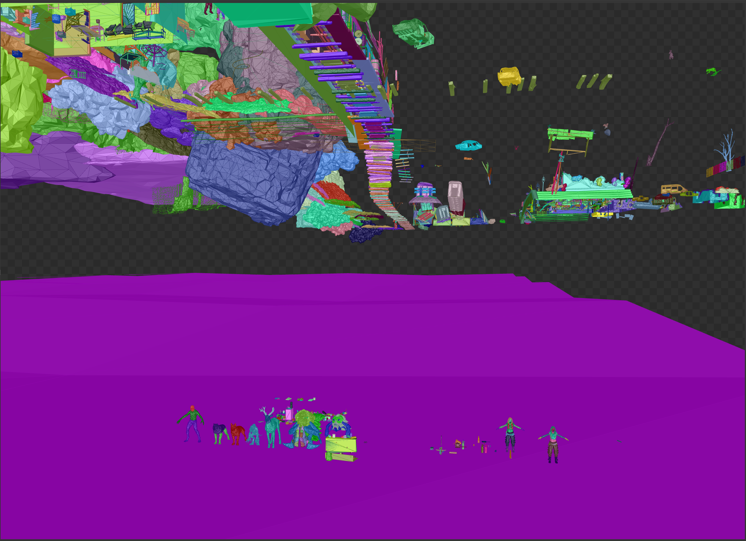
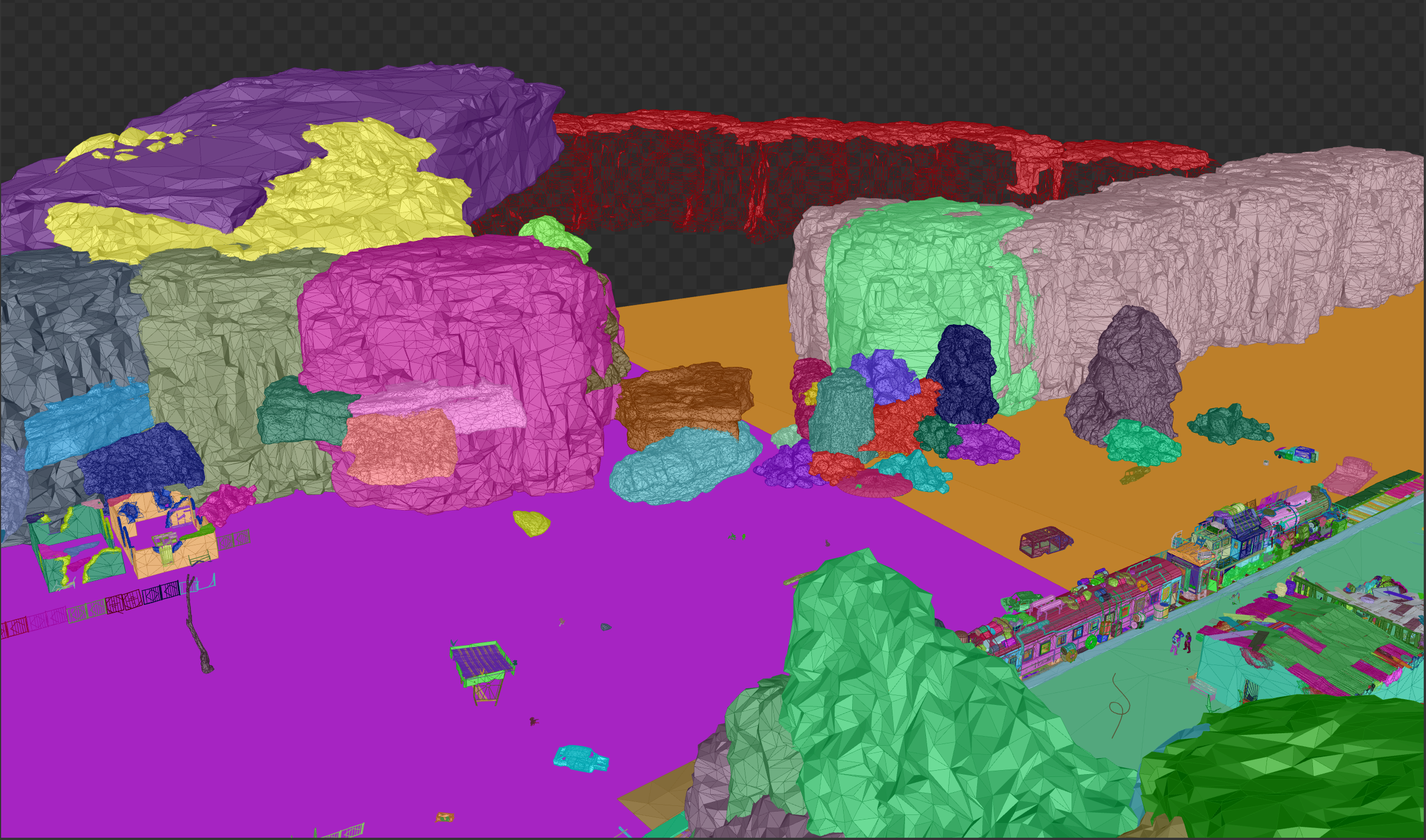
Some information about the global illumination performed by ray tracing (raytraced GI). This accelerating structure covers a large area of the game world, probably several hundred meters, while maintaining very high detail everywhere. It looks like it is somehow streaming. The scene of the accelerating structure does not coincide with the rasterized scene, for example, buildings in the image shown below are not visible in a rasterized form.
View from above
Here we can see four tiles surrounding the player’s position. The absence of geometry tested on the alpha channel is also evident. Trees have trunks, but no foliage, no grass, no bushes.
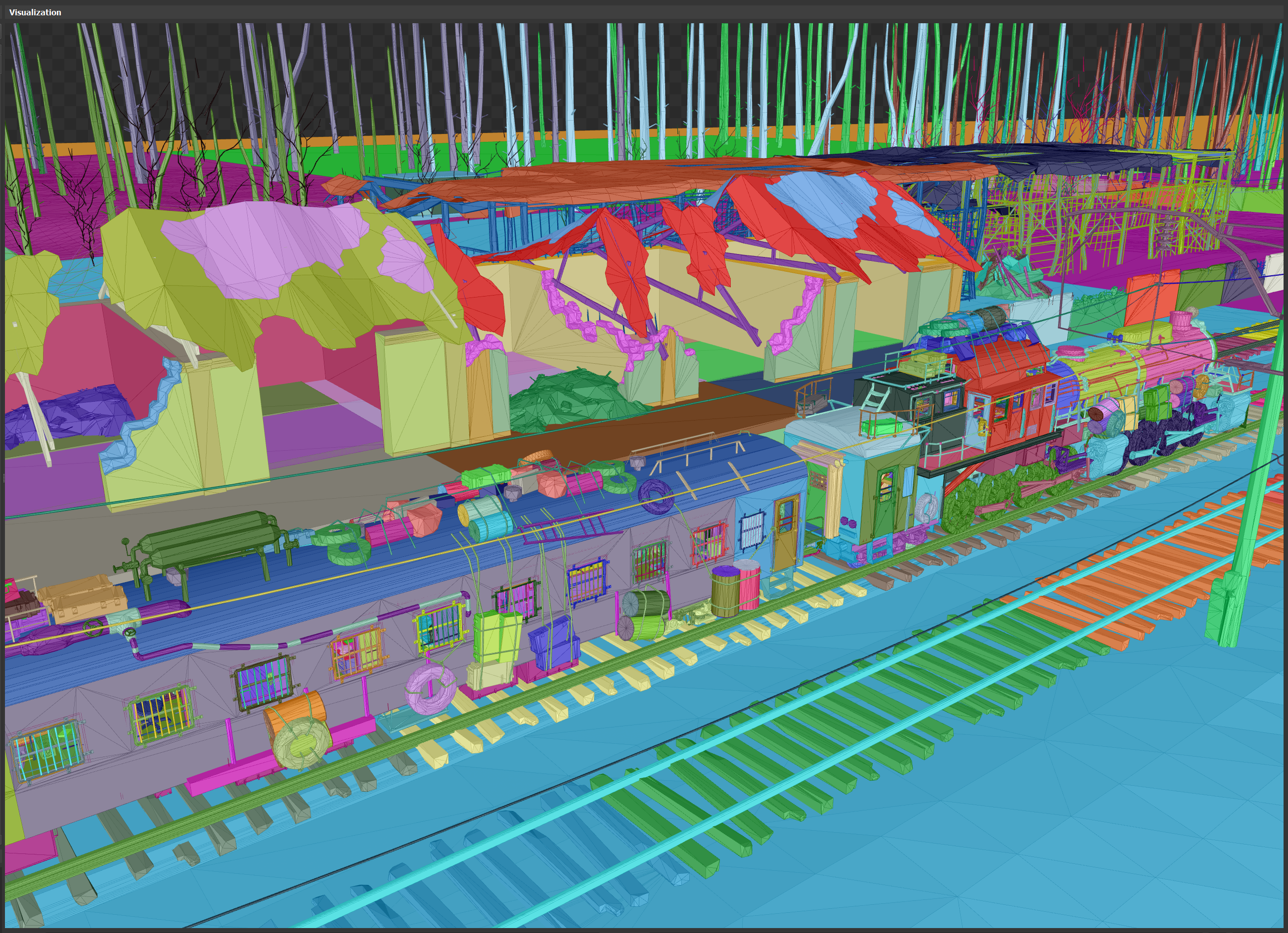
Near view
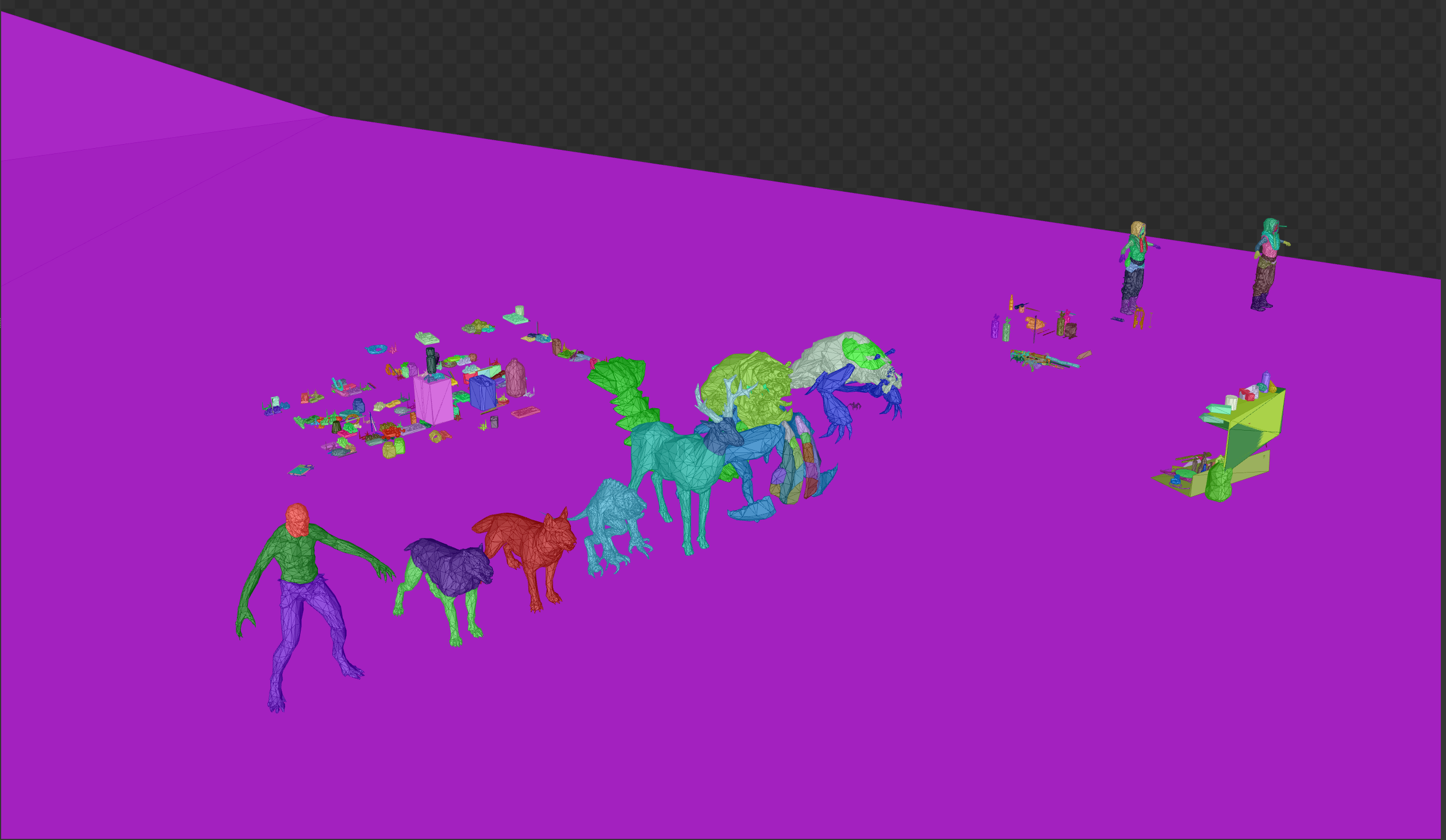
In the near view, the detail and density of objects are better seen. Each object of a different color has its own accelerating structure of the lower level. Only in this picture there are several hundred.
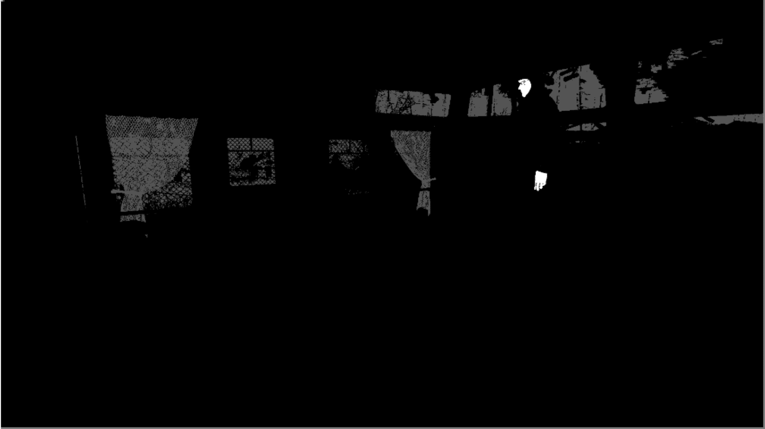
Player items underfoot
Interestingly, player items are also part of the accelerating structure, but for some reason are located under his feet.
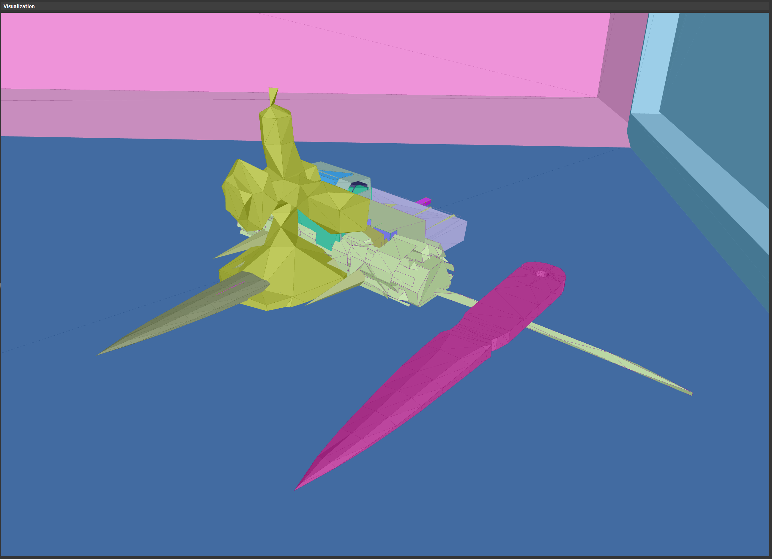
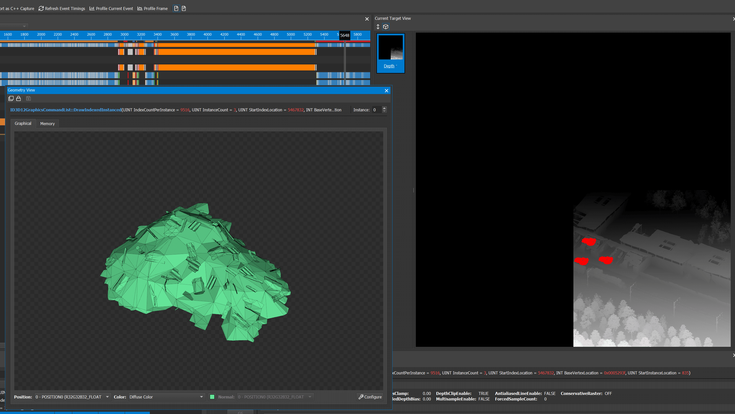
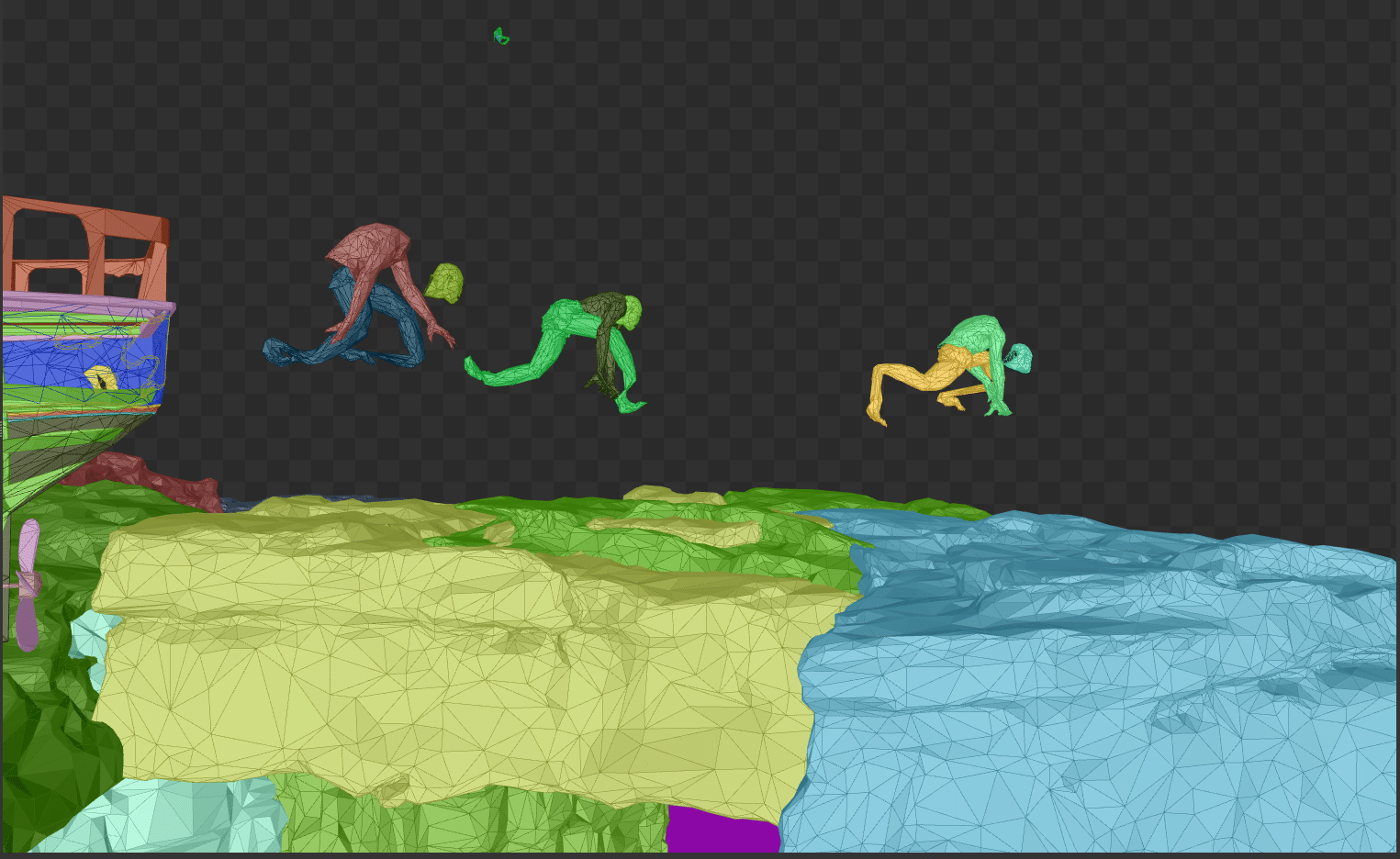
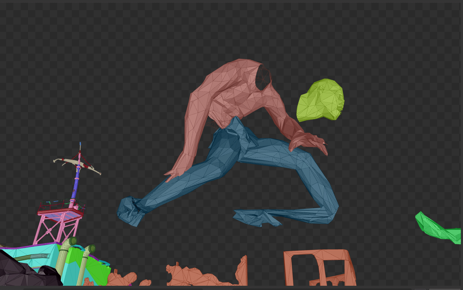
Broken skinning?
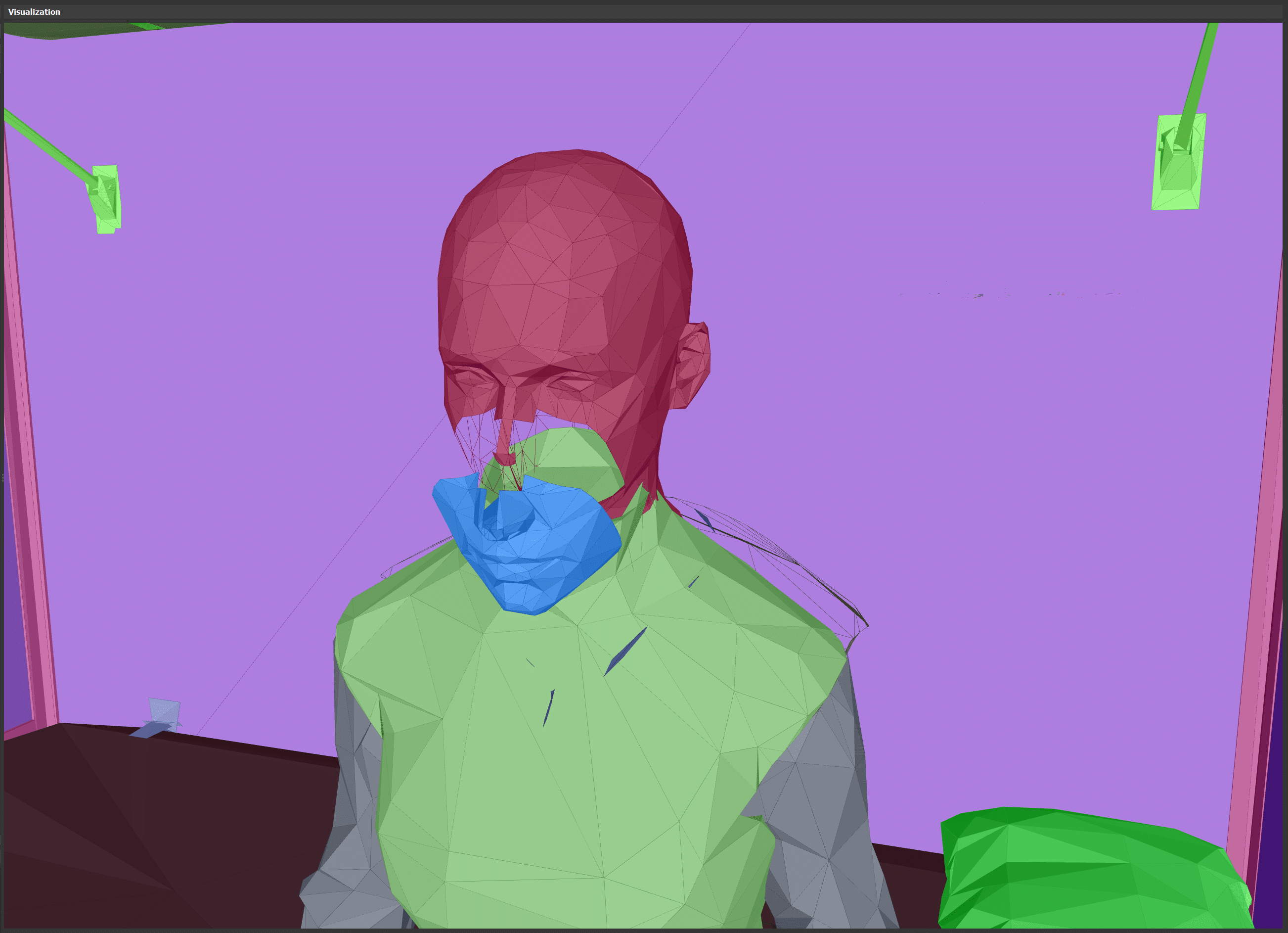
Broken skinning again?
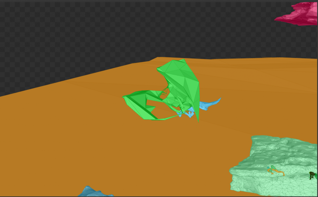
Some of the skinned objects look broken in the acceleration structure. One of the observed problems is stretching the mesh (at the feet of the child). Another problem is that the different parts of the character with skinning are in different positions. Stretching is not, but the parts are separated from each other. It seems that none of this is visible in global illumination with ray tracing, or at least I have not managed to notice this in the game.
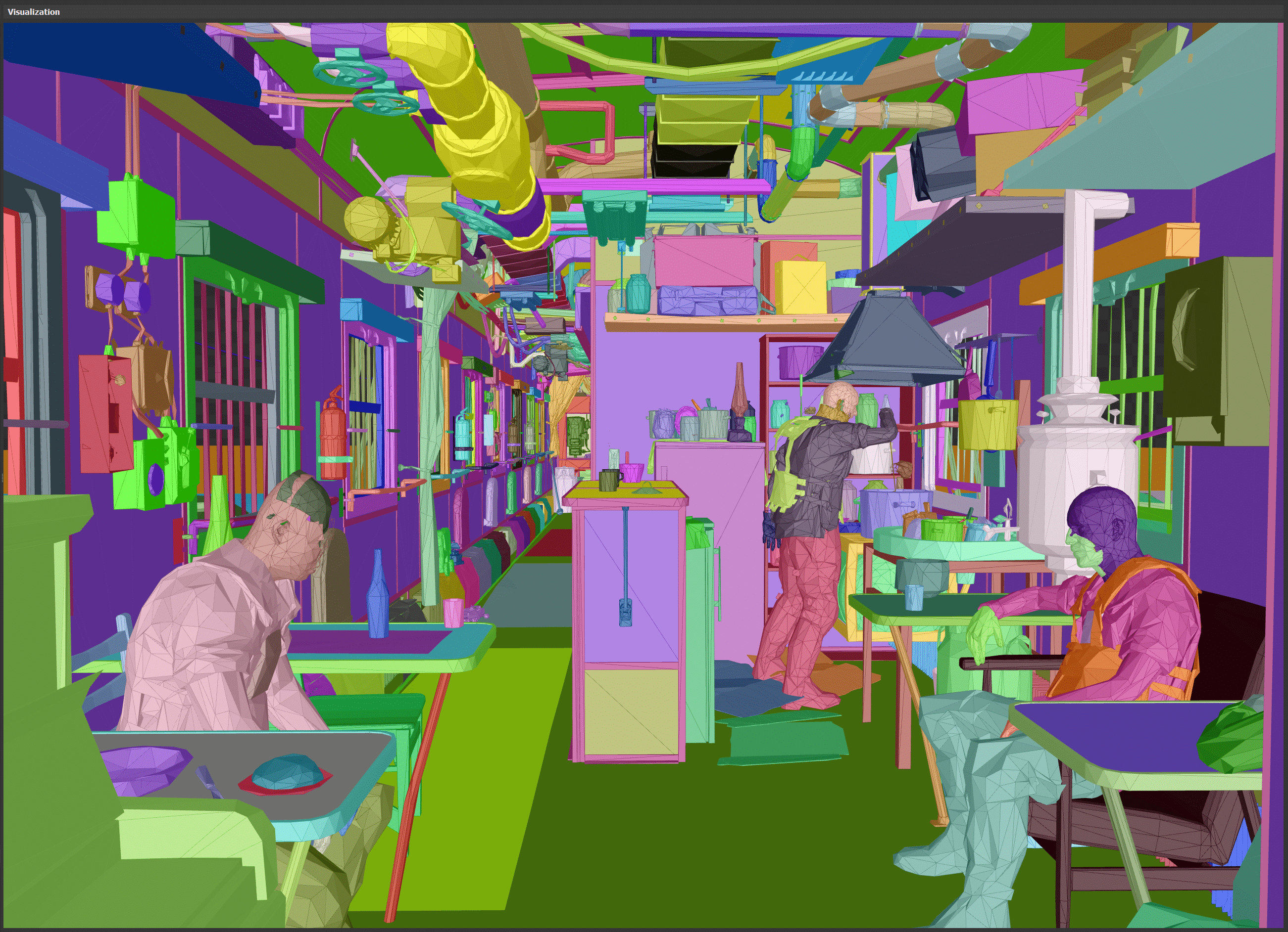
A huge number of objects
In more general terms, one can see how many different objects in the accelerating structure. Most of them in fact will not make any contribution to the results of calculations of the global distribution. It also shows that there is no LOD scheme. All objects are added with full detail. It would be interesting to know if this has any effect on ray tracing (I would suggest that yes).
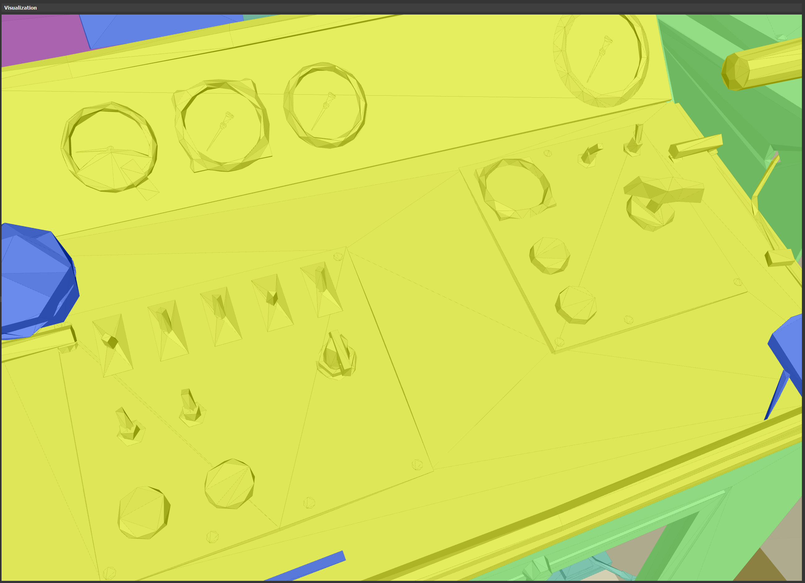
Ultra high LOD, each scale and switch is fully simulated
Another screenshot shows a huge detail of objects, even away from the player. Each switch and each scale in this image are clearly readable even without textures. The place where I moved the camera to make this screenshot is located tens of meters from the player and the elimination of these details would in no way impair the quality of the picture. An update of the accelerating structure is possible using LOD would be too costly, but there is a high probability that this update can be performed asynchronously. This moment is definitely worth exploring in more detail.
Rendering directed shadows
The main part of shadow rendering is simple and does not require any special mention, but there are interesting points here too.
Meshes for which shadows are less likely to drop
Huge detail in shadow maps
Meshes that seem to have the wrong index buffer.
It seems that, like accelerating structures, shadow rendering includes absolutely everything. There are objects that almost do not contribute to the shadow map, but they are still rendered. Interestingly, is this because of the resolution, or is there no easy way to exclude them in the engine?
There are objects that are difficult to see even with shadows in the screen space. Their conversion does not take much time, but it would be interesting to see if they can be removed to save some time.
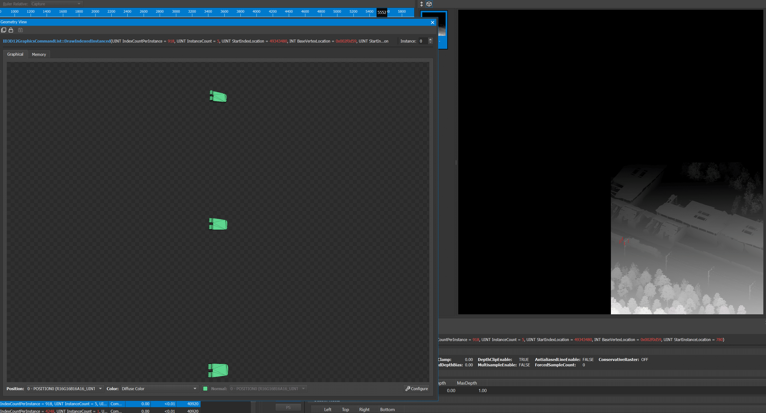
When studying a mesh, it seems that some of the meshes rendered in the shadow map have broken index buffers, but after the vertex shader they look correct (the results are the same in PIX and NSight). This is the best example I could find, but it is far from the only one. Maybe this is some kind of special packing position?
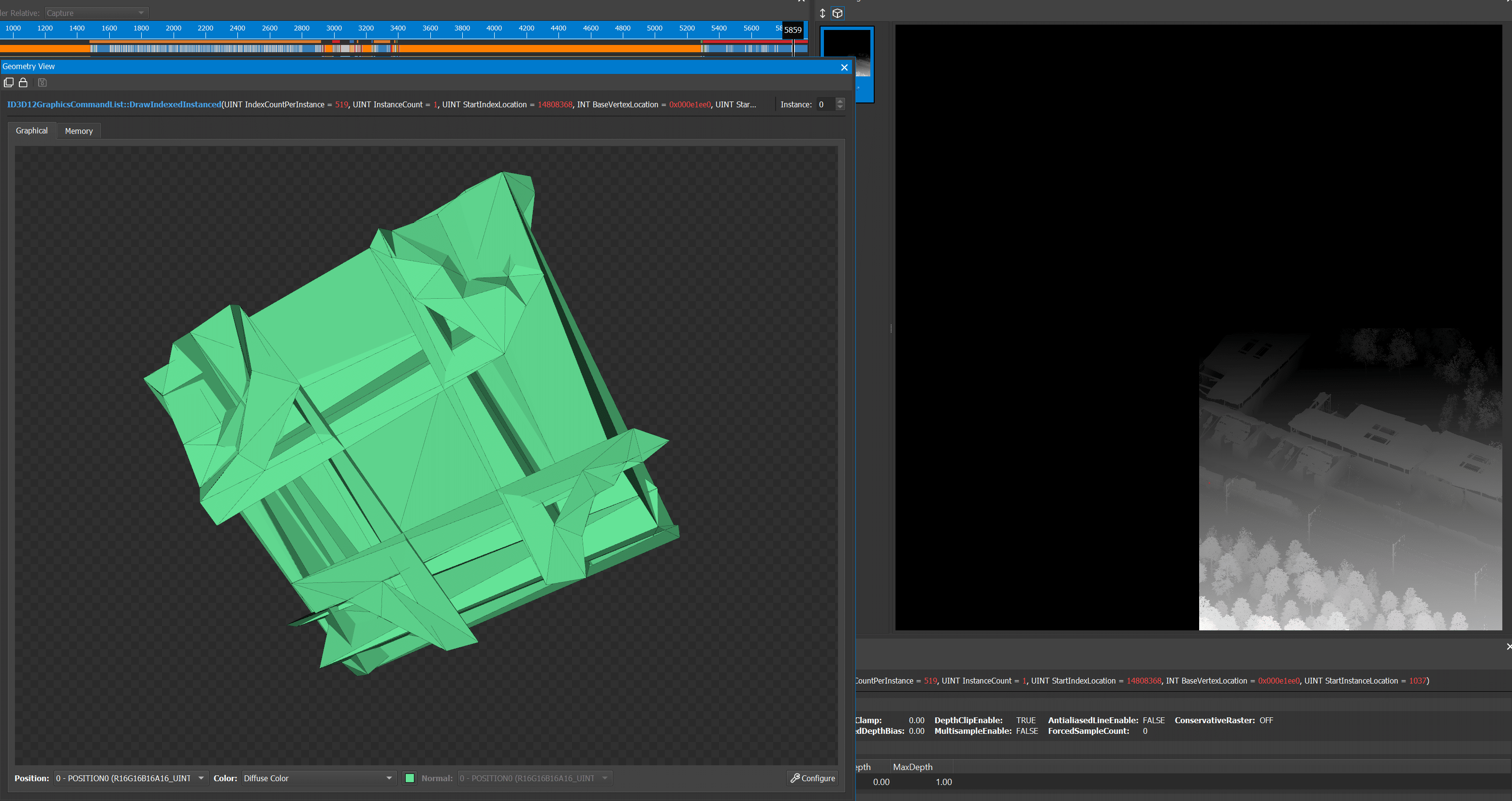
It looks like meshes have bad skinning
It seems that skinning causes problems not only in accelerating structures. Interestingly, that does not lead to visible artifacts on the screen.
Part 2

Slight amendment
In the previous part I wrote that the third render target buffer GBuffer most likely contains metalness, but it seems that in fact it contains a specular color. At first, I did not see any colors and did not understand why all three RGB channels contained the same data, but probably it was because there were no color reflections in the scene. For this weapon in the buffer contains much more different colors.
I also forgot to add my favorite texture, which I found in the process of researching the rendering of the game. It is definitely worth mentioning because it demonstrates the chaotic nature of game development when it’s not always possible to clean everything up.
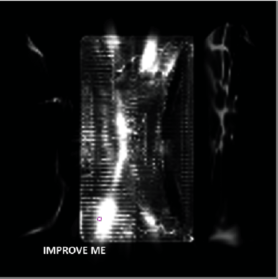
"Improve me!"
Transparency compositing and anti-aliasing
Trying to figure out how to increase the resolution of the buffer size to half the size, and how the game performs antialiasing, I noticed something curious. I needed a scene where there was much more contrast in order to clearly see what was happening. Fortunately, I managed to capture a frame in which the player’s weapon between frames slightly shifted.
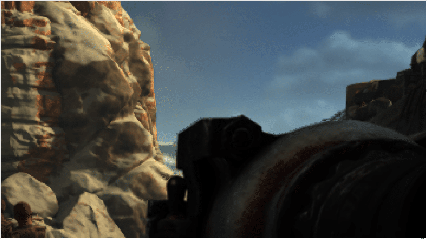
Before rendering transparency
It seems that before the transparency buffer is composted, the buffer already contains a fully rendered image, and since there are no sharp edges in this frame, it is logical to assume that this is the data from the previous frame.
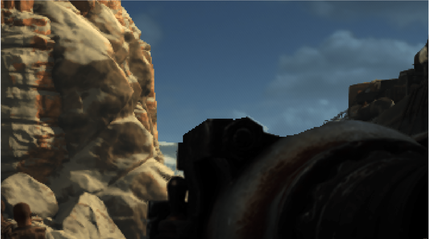
After compositing transparency of the current frame
When adding transparency to the current frame, we can notice some broken edges. It happened because the weapon shifted slightly to the right. Some clouds are rendered transparent, but they are clipped on the horizon (which is opaque), so compositing does not change the bottom, but already renders on top of the weapon mesh from the previous frame, using the depth buffer of the current frame.
After adding the opacity of the current frame
After a few draw calls, compositing and opaque meshes are performed. There seems to be no particular reason to do this in that order. It is logical to compose the transparency buffer into the data of opaque objects of the current frame, but this does not happen, and it would be interesting to know why.

After TAA
After completion of the full frame, the TAA (time smoothing) pass smooths the edges. I was already interested in this before, because I did not see where the smoothing occurs. But I missed it because immediately after this draw call, the downsampling for the bloom begins, and I missed this one draw call.
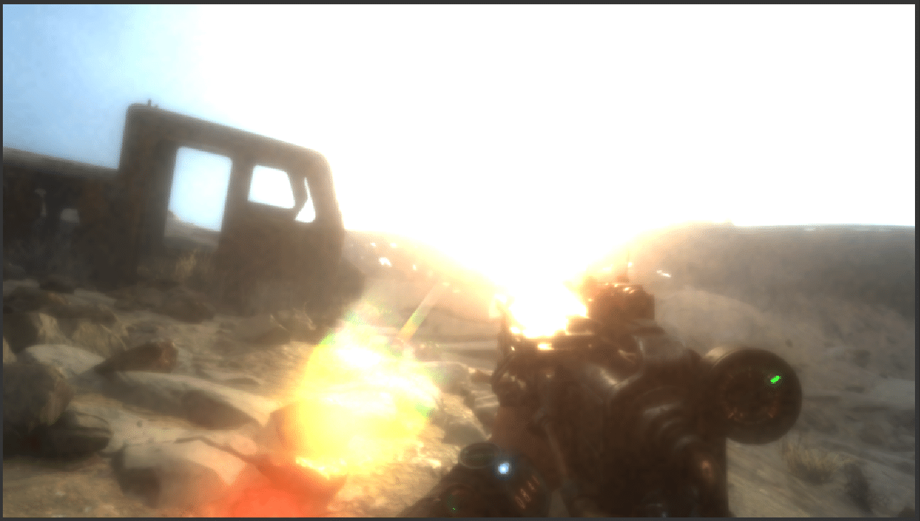
Lens flare
I usually don’t want to analyze individual effects, but there are many ways to implement lens flare, so I was curious as to which developers chose.
Lens flare in the finished compositing
In most cases, the lens flare is hardly noticeable, but this is a beautiful effect. It is difficult to show in the screenshot, so I will not put much effort into it.
Lens flare in bloom buffer
Searching, I found a draw call that adds this effect, and it turned out that it was a call after the last step of increasing the resolution of bloom. In this buffer, the effect is much more noticeable.
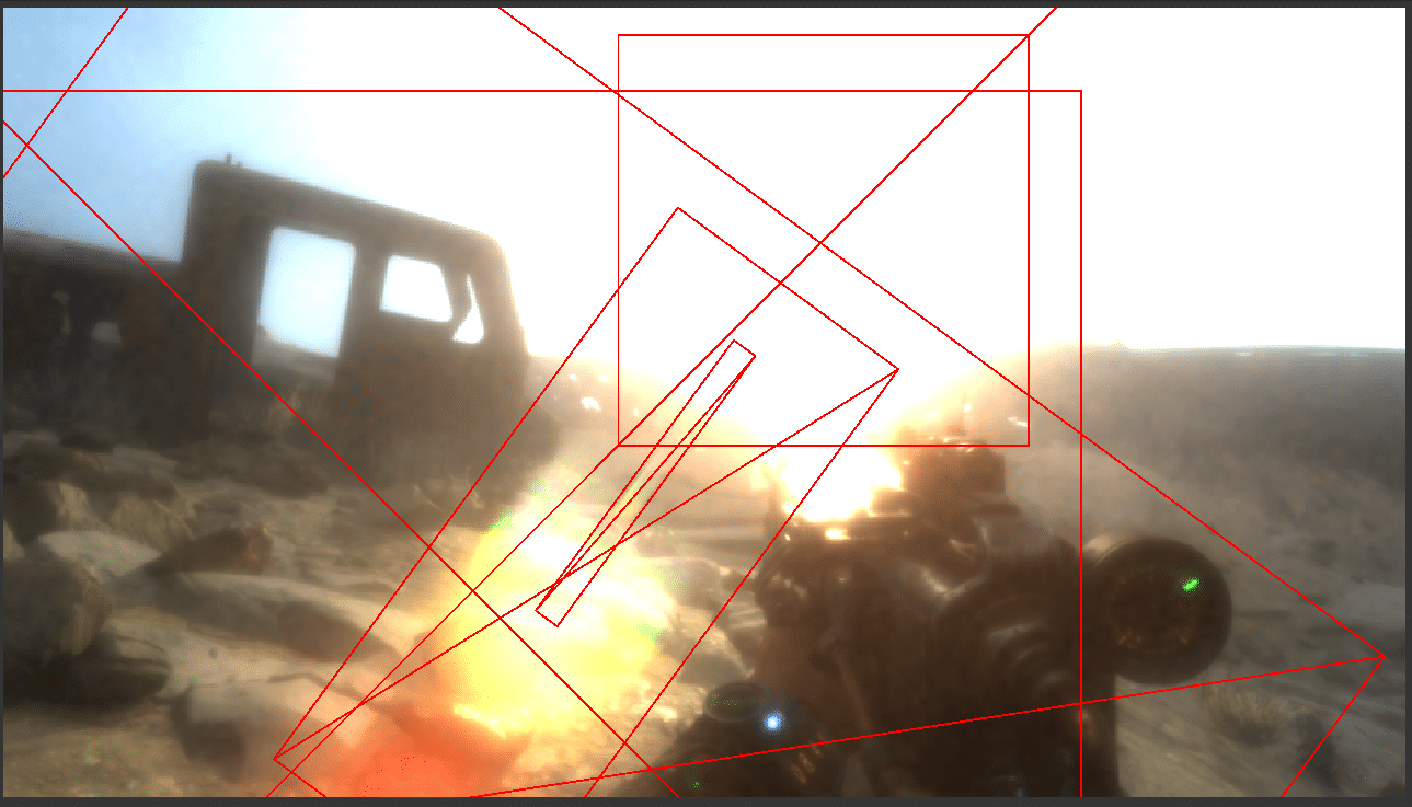
Geometry Lens flare
If you look at the geometry, the lens flare is pretty simple. Not less than 6 quadrangles are involved in creating the finished result on the screen, but there is no series of smaller quadrangles that are getting closer to the position of the sun. It can be concluded that this is a fairly standard solution, although some developers will render the lens flare directly into the render target scene, while others calculate the effect as post-processing.
Relief rendering
In all open world games, relief rendering is one of the most interesting challenges. I decided that it might seem interesting to study this aspect, but, to be honest, I was a little disappointed.
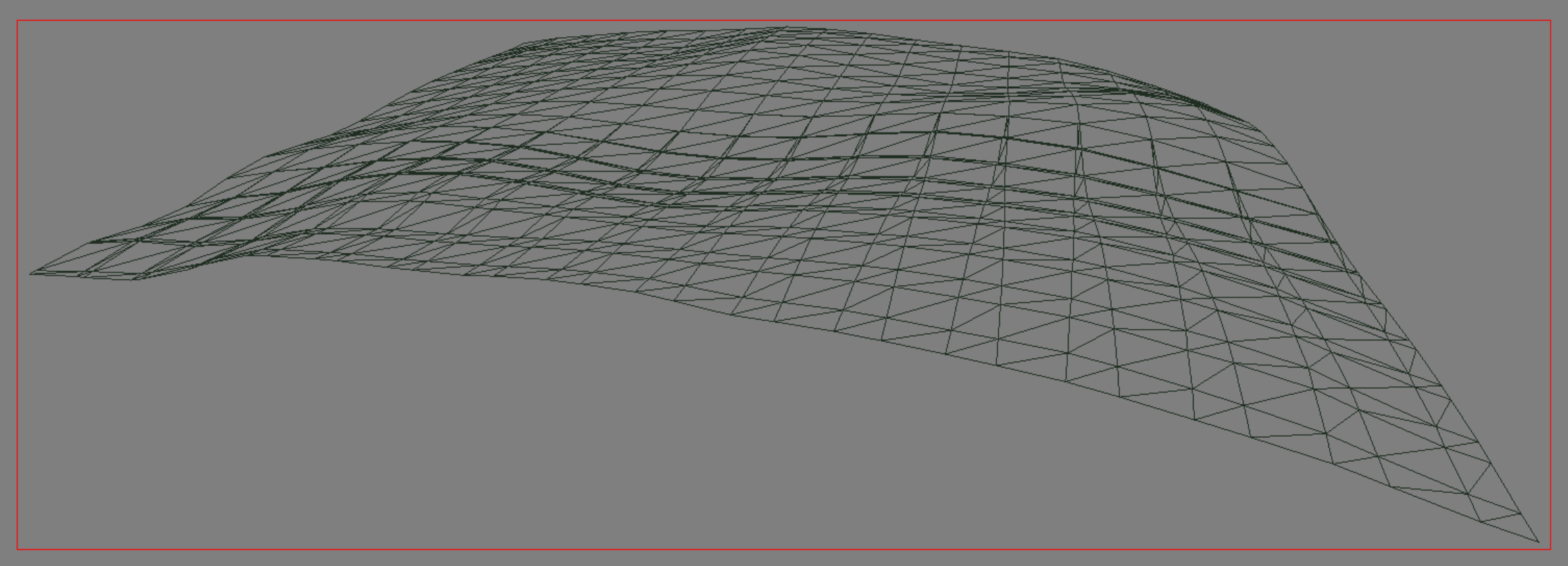
At first glance, a fragment of the relief looks like some kind of tessellation is performed. The way the relief is deformed when moving makes it logical to assume that there is some additional displacement. In addition, on the PC, the game uses tessellation quite actively, so it would be logical to use it in relief.
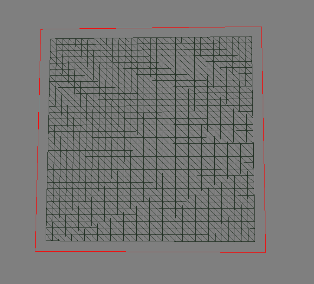
Perhaps I had the wrong parameters set, but the game renders all the relief fragments without tessellation. For each fragment of the relief it uses this uniform 32 * 32 grid. There is also no LOD.
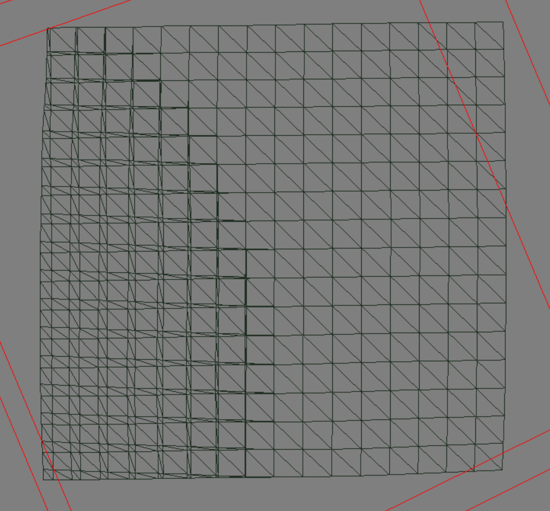
Looking at the fragment of the relief after the vertex shader, you can see that most pairs of vertices have merged, forming an almost perfect 16 * 16 grid, except for some places that require greater accuracy (probably due to the curvature of the relief). The deformation mentioned above is probably due to reading the mip-textures of the relief height map, when the relief is far from the camera.
Ray Tracing Tricks
And now about what everyone was waiting for.
Streaming data
One of the most interesting aspects of any DXR implementation at the moment is the way to work with data. The most important thing is how data is loaded into accelerating structures and how it is updated. To test this, I made two captures and compared the accelerating structures in NSight.
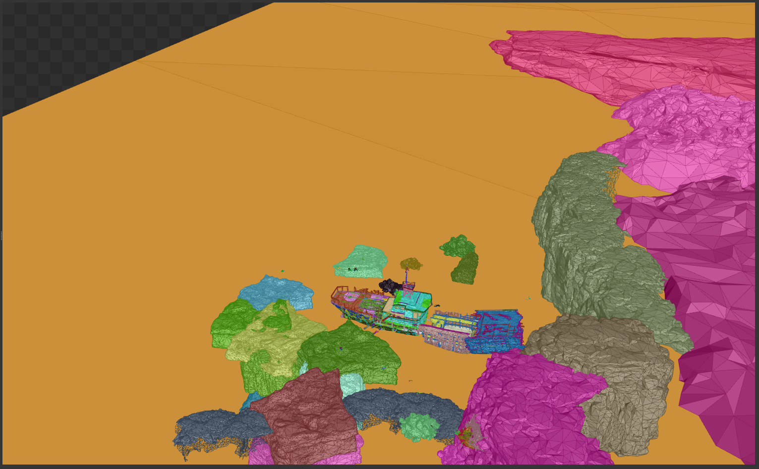
The player is inside the ship
In the first capture, I stood inside a broken ship, which is visible in the middle of this image. Only the nearest objects are loaded, except for large rocks on the edge of the map.
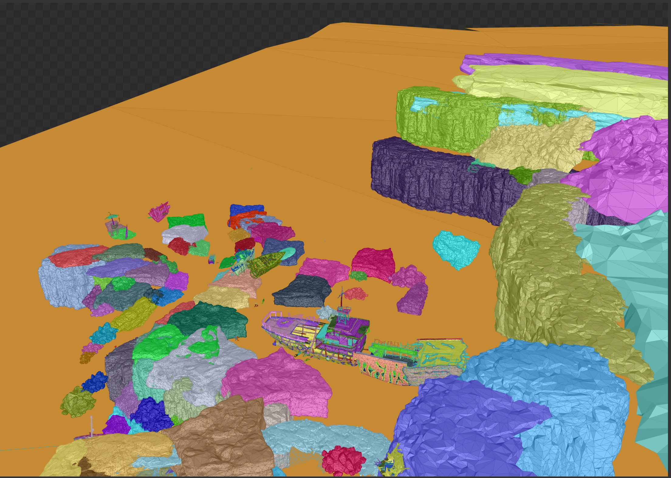
The player has moved to the upper left corner of this image.
In the second capture, I moved away from the edge of the map and turned out to be closer to the upper left edge of the image. The ship and everything around it is still loaded, but new objects also loaded. Interestingly, I cannot define any tile structure. Objects can be loaded / removed from the accelerating structure based on distance and visibility (possibly a bounding parallelogram?). In addition, the upper right edge looks more detailed, although it has moved away from it. It would be interesting to know more about this.
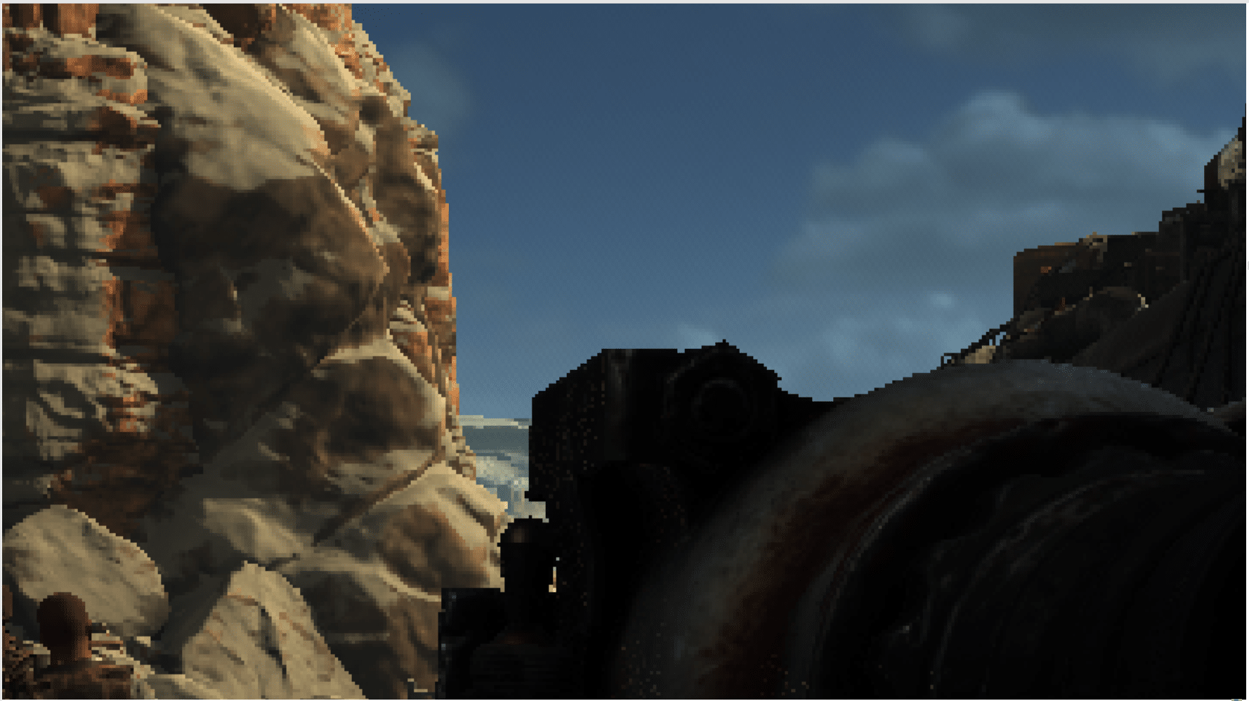
Relief and what's under it
We can mention several aspects of the implementation of DXR in Metro: Exodus, concerning the terrain.
First, it is curious that the accelerating structures do not contain any meshes of the relief (except in special cases). These monsters actually run on the ground in the game, but judging from the data in NSight, you might think that they are flying. This raises an interesting question for us: can the implementation of global illumination somehow take into account the relief (perhaps with the help of a height map and relief material), or not.
The next moment I would never have noticed if the relief was in place. Having looked at the beginning of the level at the accelerating structure in NSight, I noticed some meshes under the relief.
Artists quite often for various reasons have debug meshes below the level, but before the release of the game they are usually deleted. In this case, these meshes not only survived the release, but also became part of the accelerating structure.
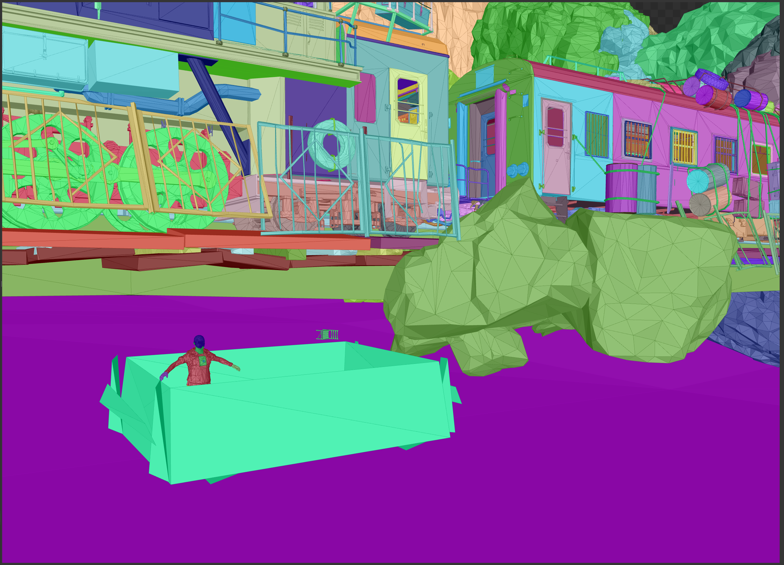
In addition to those mentioned above, I found other meshes scattered under the relief. Basically, they are not worth much mention, but this one was very interesting - it is a character standing right below the starting point of the level. He even has his own pool.
Finally, the last curious element of the accelerating structure is one-way meshes looking outside the level. Unless they are considered two-sided, they are very unlikely to contribute to the game image. Even if the meshes are two-sided, they are so far away from the playable area that they probably just stretch the accelerating structure. It is interesting to see that they are not filtered. This image also shows one of the special cases of the “mesh of relief” in the lower right corner, between the train and the building.
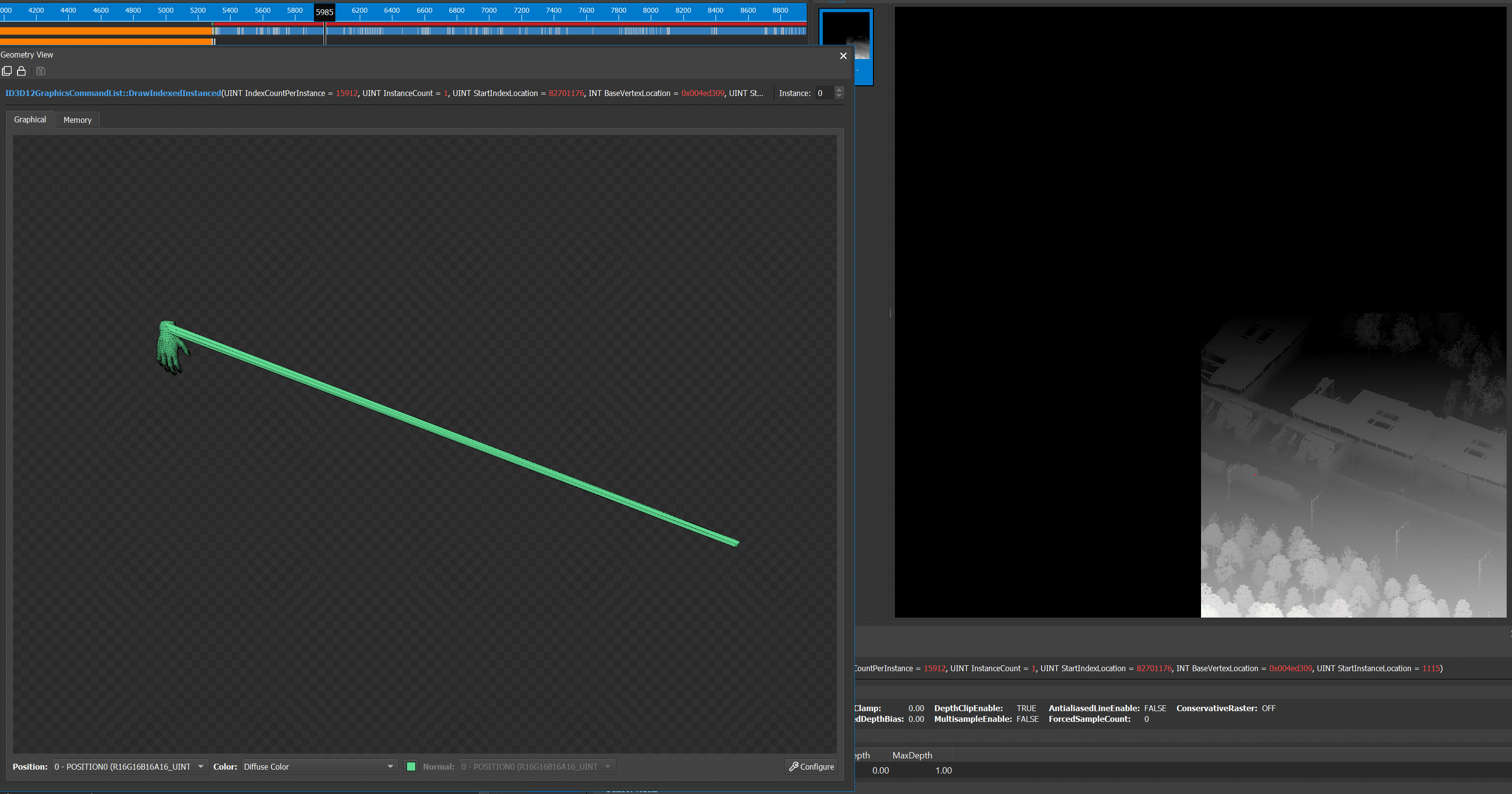
Skinless Headlessness
I have already talked about the problems of skinning meshes, but at this level I noticed something else.
Firstly, this monster shows both errors in one image, which I noticed above. I'm still wondering what they are caused by.
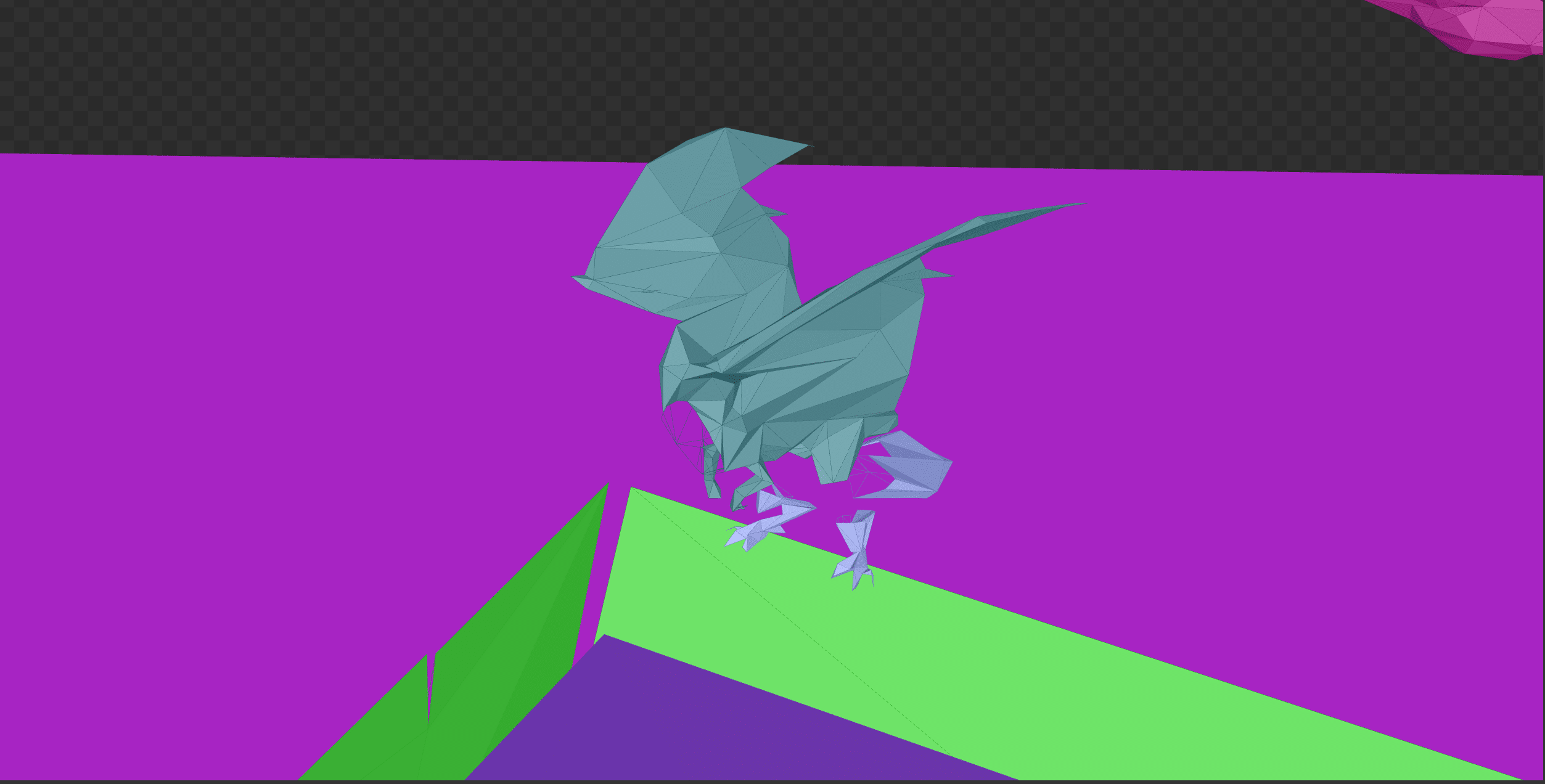
I also noticed that these small creatures that look like bats do not have heads in the accelerating structure.
One more example. Note the hole where the head should be. I have not seen a single case where the head was visible.
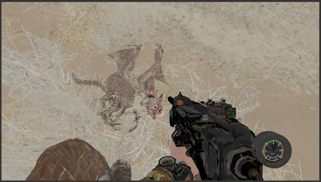
The same kind of creatures in rasterization mode. Note that the head is clearly visible.
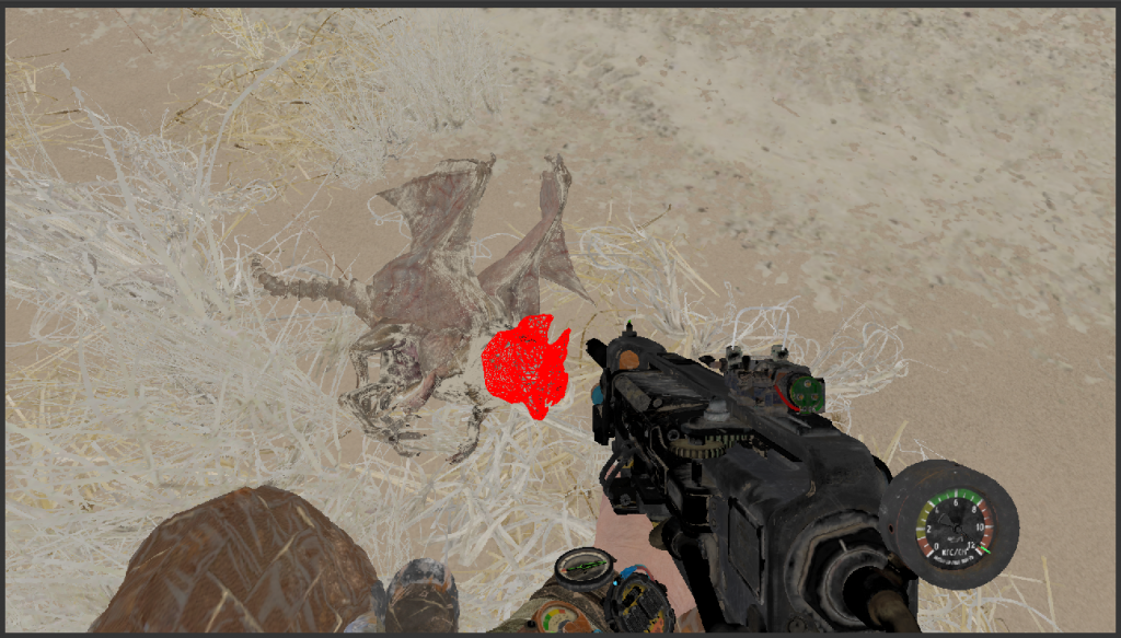
But the frame display of the head.
Finally
That's all for today. I hope you enjoyed this look at the insides of Metro: Exodus.
I will continue to explore the rendering of the game, but I will not publish new parts of the article if I do not find any special parts that would be interesting to people, or find something worth sharing.
Source: https://habr.com/ru/post/447194/
All Articles