Local autonomous data collection system
At the company, NEKST-M monitoring posts of domestic production Nekst Technologies were purchased. To ensure the visualization of the pumping units,
fire alarm, voltage on the starters, room temperature, emergency water level. The heart of NEKST-M is ATMEGA 1280, and this fact was encouraging in terms of the possibility of creating its own set for specific needs.
The task was set in the shortest possible time and at minimum cost to create a fully autonomous system of local dispatching for specific needs. The basis of the microcontroller. Development, manufacturing, created by the staff itself.
The system should work without dependence on cellular networks, servers, the Internet and an authorization system of using radio frequency resources, not use computers or maximum periodic use of laptops in the control and management system, without access to objects for a long time (6-9 months). The network configuration has a radial structure. Data is collected at one point and then sent for processing via normal communication channels or as a hard copy.
The system should provide:
')
Working conditions:
In spite of such strict requirements, the implementation is quite simple in the phased solution of the problem.
Taking everything into account, the Arduino Nano 3.0 board has become the “brain” of the plan. The “Robotdyn” shawl has an ATMEGA 328 controller, the required voltage regulator is 3.3V per
800 mA current and converter to CH340G UART-USB.
First of all, the operating time counters were created as the most relevant. Previously used industrial meters assembled on PICs with a transformerless power supply circuit failed due to voltage surges during the year of operation. Only the connected ones with the help of self-made power supplies with a voltage of 5V remained intact. To speed up the installation and the universality of the connection, the signal on the state of the units is taken from the terminals of the switching devices, i.e. registration of the presence of the 1st phase voltage at three-phase power supply 380V. For coordination with the controller, an intermediate relay with a winding of 220V or an optocoupler composed of a LED and a GL5516 photoresistor or an PC817 optocoupler is used. All variants were tested in work. The LED is powered by a rectified voltage with current limiting by means of two capacitors CBV22 designed for 630V connected in series for safety when randomly checking circuits with a megohmmeter.
Reading the operating time using the ST7735S LCD screen, transmitting data over the radio channel in real time using the E01-ML01DP05 module at 2.4 MHz. This device contains the nRF24L01 + chip and the RFX2401C transmit / receive amplifier,
output power up to 100 mW. Spiral antennas designed for the desired range in the online site calculator. The choice of the type of antennas is due to the exception of receiving once reflected waves from the surrounding metal structures. Details of the antennas are printed on a 3D printer. The current state of the counters is stored in the controller's EEPROM and is restored in the event of an unexpected power outage. The time intervals for the account are provided by the RTC chip DS3231 as a module with a battery backup power supply. The power supply unit uses 3 modules, the HLK-PM01 600mA switching source 220 / 5V, the HW-553 and 03962A converter from 1-5V to 5V - a battery controller with a circuit for protection against short circuit, overdischarge and overcharge. All components were purchased on Aliexpress.
4-channel counter. The inputs are LC filters to protect against interference on the communication line of twisted pair. Data on the status of objects of control are constantly read once per second, displayed in color on the LCD. Updating of indications and record in non-volatile memory happens each 36 sec. 36 seconds is 1/100 of an hour, data is required in this format. Every 12 sec. information is transmitted on the number of seconds of work for each control unit. EEPROM memory has a limited number of write-erase cycles, according to the manufacturer, 100,000 times. The worst option is when constantly updating at least one cell. The volume of the 1st counter is 4 bytes, this is a long format number, 4 counters, a total of 16 bytes occupies one record. The memory length of the microcircuit is 1024 bytes; after 64 records of 4 counters, the recording will begin again. In the EEPROM library, the EEPROM.put method does not write, if the value of the cell and the recorded information is the same, there will be no cell degradation. As a result, the time guaranteed memory will be more than 7 years. Time possible, but non-guaranteed work can be much more.
Small remarks at the end. The score is at a low logic level at the inputs.
Tightening resistance R2-R5 36 kOhm for the version with photoresistors GL5516. In the case of phototransistor optocouplers and relays, put 4.7-5.1 kOhm. Loader Arduino Nano v3.0 replaced by Arduino Uno using the programmer TL866A for correct operation of the watchdog timer. The fuses are corrected for operation at a voltage higher than 4.3 V. The external reset circuit R6 C3 was not used. In the example program, the transmitter frequency does not correspond to the unlicensed range, the 2.4 MHz range is limited to the frequencies 2400.0–2483.5 MHz.
The range of the E01-ML01DP05 transmitter is 2400-2525 MHz. The bandwidth of one channel is 1 MHz, when setting the speed as “RF24_2MBPS”, the specified radio.setChannel (120) channel and the next one, i.e. the band will be 2 MHz.
fire alarm, voltage on the starters, room temperature, emergency water level. The heart of NEKST-M is ATMEGA 1280, and this fact was encouraging in terms of the possibility of creating its own set for specific needs.
The task was set in the shortest possible time and at minimum cost to create a fully autonomous system of local dispatching for specific needs. The basis of the microcontroller. Development, manufacturing, created by the staff itself.
The system should work without dependence on cellular networks, servers, the Internet and an authorization system of using radio frequency resources, not use computers or maximum periodic use of laptops in the control and management system, without access to objects for a long time (6-9 months). The network configuration has a radial structure. Data is collected at one point and then sent for processing via normal communication channels or as a hard copy.
The system should provide:
')
- control of pumping units
- technological automation
- emergency protection
- emergency alarm
- life time counting
- calculation of the amount of electricity consumed
- temperature control equipment
- fire and security alarm
- periodic remote removal of information
- unknown requirements in the future
Working conditions:
- coverage area of 1 sq. km.
- line-of-sight between objects
- temperature from +50 to -50
- humidity up to 100%
- biologically active deposits (mold, sulfate-reducing bacteria)
- vibration, no more, cars of 1–2 classes in accordance with GOST ISO 10816-1-97
- Electromagnetic environment - switching of electric motors by KT 6053 contactors, RVS-DN soft start equipment, SIEMENS MICROMASTER PID control equipment, ISM and GSM emissions according to the requirements for these devices, on-site manual arc welding
- Overvoltage of the network, short-term power outages, thunderstorm overvoltages, phase imbalance when the VL wire is broken in 6-10 kV distribution networks.
In spite of such strict requirements, the implementation is quite simple in the phased solution of the problem.
Taking everything into account, the Arduino Nano 3.0 board has become the “brain” of the plan. The “Robotdyn” shawl has an ATMEGA 328 controller, the required voltage regulator is 3.3V per
800 mA current and converter to CH340G UART-USB.
First of all, the operating time counters were created as the most relevant. Previously used industrial meters assembled on PICs with a transformerless power supply circuit failed due to voltage surges during the year of operation. Only the connected ones with the help of self-made power supplies with a voltage of 5V remained intact. To speed up the installation and the universality of the connection, the signal on the state of the units is taken from the terminals of the switching devices, i.e. registration of the presence of the 1st phase voltage at three-phase power supply 380V. For coordination with the controller, an intermediate relay with a winding of 220V or an optocoupler composed of a LED and a GL5516 photoresistor or an PC817 optocoupler is used. All variants were tested in work. The LED is powered by a rectified voltage with current limiting by means of two capacitors CBV22 designed for 630V connected in series for safety when randomly checking circuits with a megohmmeter.
Reading the operating time using the ST7735S LCD screen, transmitting data over the radio channel in real time using the E01-ML01DP05 module at 2.4 MHz. This device contains the nRF24L01 + chip and the RFX2401C transmit / receive amplifier,
output power up to 100 mW. Spiral antennas designed for the desired range in the online site calculator. The choice of the type of antennas is due to the exception of receiving once reflected waves from the surrounding metal structures. Details of the antennas are printed on a 3D printer. The current state of the counters is stored in the controller's EEPROM and is restored in the event of an unexpected power outage. The time intervals for the account are provided by the RTC chip DS3231 as a module with a battery backup power supply. The power supply unit uses 3 modules, the HLK-PM01 600mA switching source 220 / 5V, the HW-553 and 03962A converter from 1-5V to 5V - a battery controller with a circuit for protection against short circuit, overdischarge and overcharge. All components were purchased on Aliexpress.
Bread board
4-channel counter. The inputs are LC filters to protect against interference on the communication line of twisted pair. Data on the status of objects of control are constantly read once per second, displayed in color on the LCD. Updating of indications and record in non-volatile memory happens each 36 sec. 36 seconds is 1/100 of an hour, data is required in this format. Every 12 sec. information is transmitted on the number of seconds of work for each control unit. EEPROM memory has a limited number of write-erase cycles, according to the manufacturer, 100,000 times. The worst option is when constantly updating at least one cell. The volume of the 1st counter is 4 bytes, this is a long format number, 4 counters, a total of 16 bytes occupies one record. The memory length of the microcircuit is 1024 bytes; after 64 records of 4 counters, the recording will begin again. In the EEPROM library, the EEPROM.put method does not write, if the value of the cell and the recorded information is the same, there will be no cell degradation. As a result, the time guaranteed memory will be more than 7 years. Time possible, but non-guaranteed work can be much more.
Schematic diagram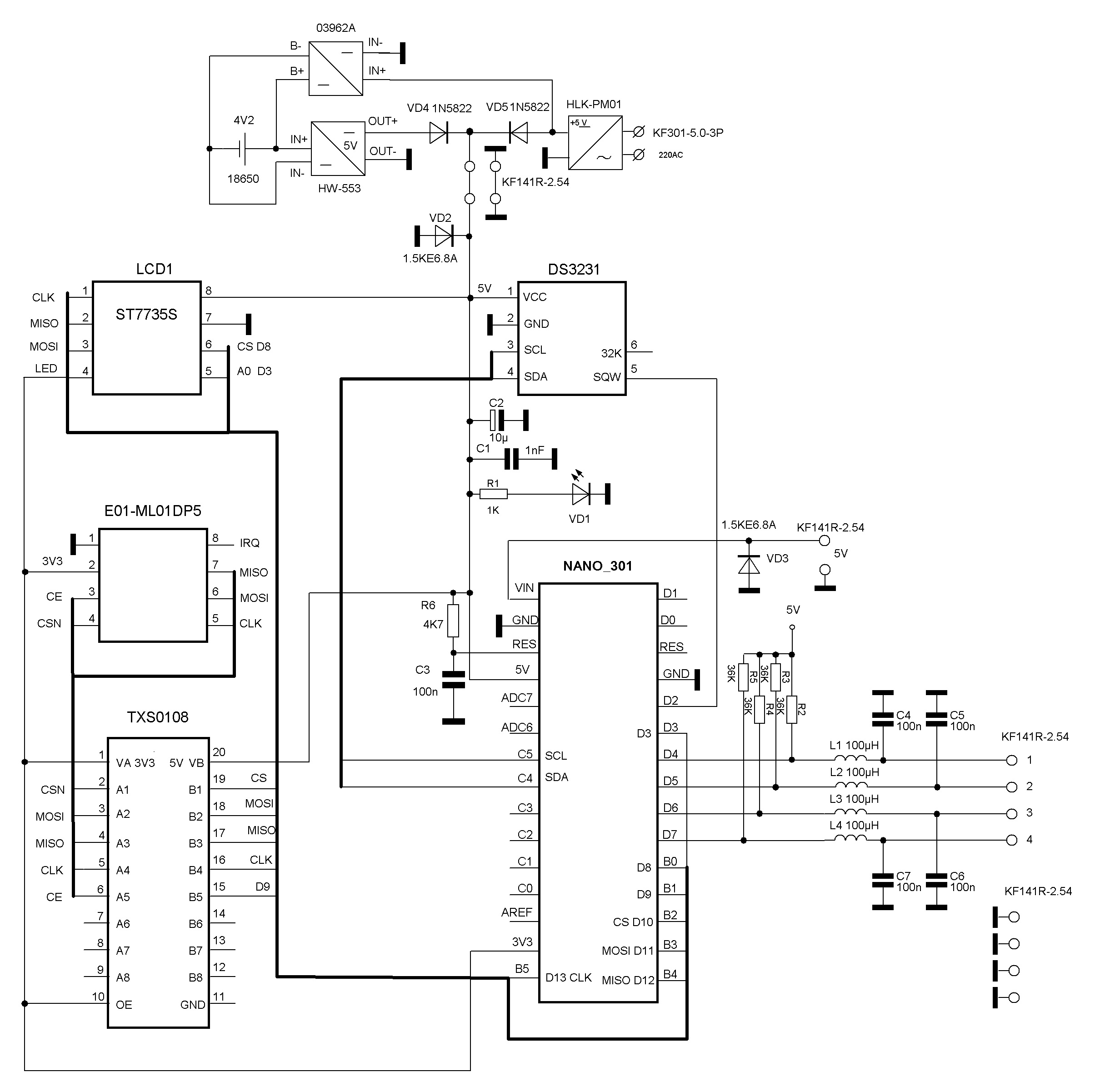
Program in the Arduino IDE
// 12 328 bytes (38%)
#include <Adafruit_GFX.h> // Core graphics library
#include <Adafruit_ST7735.h> // Hardware-specific library
#include <SPI.h>
#include <EEPROM.h>
#include <Wire.h>
#include <nRF24L01.h>
#include <RF24.h>
RF24 radio (9, 10); // radio object for working with RF24 library,
// and pin numbers nRF24L01 + (CE, CSN)
#include <DS3231.h>
DS3231 rtc (SDA, SCL);
Time t;
// # define TFT_CS 10
#define TFT_CS 8
#define TFT_RST -1 // you can also connect this to the Arduino reset
// in which case, set this #define pin to -1!
// # define TFT_DC 9 // DC = RS = A0- variants of notation for the output of the selection of the register of commands or data.
#define TFT_DC 3
Adafruit_ST7735 tft = Adafruit_ST7735 (TFT_CS, TFT_DC, TFT_RST);
// Option 2: use any pins but a little slower!
#define TFT_SCLK 13 // set these to be whatever you like!
#define TFT_MOSI 11 // set these to be whatever you like!
// Adafruit_ST7735 tft = Adafruit_ST7735 (TFT_CS, TFT_DC, TFT_MOSI, TFT_SCLK, TFT_RST);
#include <avr / wdt.h>
byte shift = 52;
byte pinState;
unsigned long pump [4]; // array with 4 values of seconds counters
float m = 3600.0;
unsigned int address = 0;
int rc; // variable for counters
unsigned long sumprim = 0;
unsigned long sumsec = 0;
byte i = 0;
byte k = 34;
unsigned int z = 0;
byte b = B00000001;
byte pumrcounter [4]; // array for storing object states, 1- off, 0- on.
int start = 0; //
void setup () {
rtc.begin ();
radio.begin (); // Initiate nRF24L01 + operation
radio.setChannel (120); // data transmission channel (from 0 to 127).
radio.setDataRate (RF24_250KBPS); // data transfer rate (RF24_250KBPS, RF24_1MBPS, RF24_2MBPS).
radio.setPALevel (RF24_PA_MAX); // transmitter power (RF24_PA_MIN = -18dBm, RF24_PA_LOW = -12dBm,
// RF24_PA_HIGH = -6dBm, RF24_PA_MAX = 0dBm)
radio.openWritingPipe (0xAABBCCDD11LL); // Open the pipe with the identifier for data transfer
// To set the time - uncomment the necessary lines
//rtc.setDOW (1); // Day of the week
//rtc.setTime (21, 20, 0); // Time, in the format of 24 hours.
//rtc.setDate (2929, 10, 2018); // Date, October 29, 2018
tft.initR (INITR_BLACKTAB); // initialize a ST7735S chip, black tab
// Use this initializer (uncomment) if you are using a 1.44 "TFT
//tft.initR(INITR_144GREENTAB); // initialize a ST7735S chip, RED rcB tab
tft.setTextWrap (false); // Allow text to run off right edge
tft.setRotation (2); // for BLACK PCB and RED tft.setRotation (0) or not.
tft.fillScreen (ST7735_BLACK); // clear the screen
DDRD = DDRD | B00000000;
PORTD = PORTD | B11110000; // software tightening works, high level-
// monitored objects “do not work”, all 4 senior ports D are recorded as “1”, no counting is going on.
for (rc = 0; rc <4; rc ++)
{
tft.setCursor (3, rc * 10 + shift); // output position numbers of control objects
tft.print (rc + 1);
}
tft.setCursor (12, 0); // output 3 lines of text
tft.println ("DEVELOPERS & BUILD"); // to praise your loved ones
tft.setCursor (24, 10); // or evil copyright
tft.print ("DEVELOPER MM");
tft.setCursor (28, 20);
tft.print ("BUILD-ER DD");
//data recovery////////////////////////////////////////////// ///////////
for (z = 0; z <1023; z + = 16) {// Enumerates all the cells of its industry
// and writes to the array of 4 pump variables, 4 bytes each counter, since
// variable unsigned long. Counters 4, one record of all 4 takes 16 bytes.
EEPROM.get (z, pump [0]); // so, without a for loop, less volume
EEPROM.get (z + 4, pump [1]);
EEPROM.get (z + 8, pump [2]);
EEPROM.get (z + 12, pump [3]);
// assignment of the next new value of the sum of 4-x counters
sumprim = (pump [0] + pump [1] + pump [2] + pump [3]);
// compares the new value of the sum of 4 counters in the variable sumprim with the previous value in the variable
// sumsec and if the previous amount is less than or equal to the new amount, a new greater or equal is assigned
// sumsec value.
if (sumsec <= sumprim) {
sumsec = sumprim; //
// and the current value z is assigned to the variable z, z is the address of the beginning of the block of 16 bytes from 4 values
// counters recorded at the same time (since when a port is polled, all its 8 bits are recorded simultaneously,
// including our needed high 4 bits of port D).
address = z;
}
}
// once again, accessing the memory of the e-industry at the address of the beginning of the block is 16 bytes from the 4 values of the counters recorded
// last, i.e. values before shutting down or rebooting due to a hang. Last record
// values of counters in an array of 4 pump variables.
EEPROM.get (address, pump [0]);
EEPROM.get (address + 4, pump [1]);
EEPROM.get (address + 8, pump [2]);
EEPROM.get (address + 12, pump [3]);
address + = 16; // increment the address to write the next block without erasing the last record
// end of data recovery ///////////////////////////////////////////// ///////////////////
attachInterrupt (0, count, RISING); // pin D2, resolution of work of interruption, every second come
// pulses from RTC DS3231 from SQW output
wdt_enable (WDTO_8S); // start the watchdog timer, reload the controller in case of a hang, time
// for which you need to issue a wdt_reset timer reset command (and avoid rebooting during normal operation - 8 seconds.
// for tests it is not recommended to set the value to less than 8 seconds. In this case, the timer is reset in
// digging, but it is every second.
}
void loop () {
// empty cycle, there will be control over the non-phase-phase operation of the electric motor
}
void count () {
tft.setTextColor (ST7735_WHITE); // set the font color
t = rtc.getTime (); // read time
tft.setCursor (5, 120); // set the cursor position
tft.fillRect (5, 120, 50, 7, ST7735_BLACK); // clear time display area
tft.print (rtc.getTimeStr ()); // display hours
wdt_reset (); // reset the watchdog timer every cycle, i.e. a second
for (rc = 0; rc <4; rc ++) // the beginning of the state input matching cycle
// bits of the port to the previous read state of the bits of port D
{
pinState = (PIND >> 4) & (b << rc);
if (pumrcounter [rc]! = pinState) {// and if it doesn't match, then
pumrcounter [rc] = pinState; // assignment of the state variable of the port bit to the new value 1/0
}
// indication of the state of objects of color control
// BLUE is a small glitch of the available screen (or library?), RGB and BGR are confused.
if (pinState == (b << rc)) {
tft.fillRect (15, ((rc * 10 + shift)), 7, 7, ST7735_BLUE); // for low counting, change GREEN to BLUE
} else {
tft.fillRect (15, ((rc * 10 + shift)), 7, 7, ST7735_GREEN); // for low counting, change BLUE to GREEN
pump [rc] + = 1; // add to the time counter 1 second
}
}
k ++;
if (k = 36) {
k = 0;
tft.fillRect (30, shift, 97, 40, ST7735_BLACK); // clear the running time display area
tft.fillRect (60, 120, 73, 7, ST7735_BLACK); // and dates
tft.setCursor (60, 120); // set the cursor position
tft.print (rtc.getDateStr ()); // display date on LCD screen
for (rc = 0; rc <4; rc ++) // output of the operating time readings in integers, tenths and
{
tft.setCursor (30, rc * 10 + shift); // hundredths of an hour with screen down by 10 pixels
tft.println (pump [rc] / m);
}
// write raw values (in seconds) in the EEPROM //////////////////////////////
for (rc = 0; rc <4; rc ++)
{
EEPROM.put (address, pump [rc]);
address + = sizeof (float); // increment of the variable address of the entry
}
}
// send data by radio from data indicating how many bytes should be sent.
if ((k == 6) || (k == 18) || (k == 30)) {
unsigned long data;
radio.write (& start, sizeof (start));
for (i = 0; i <4; i ++) {
data = pump [i];
radio.write (& data, sizeof (data));
}
}
}
Small remarks at the end. The score is at a low logic level at the inputs.
Tightening resistance R2-R5 36 kOhm for the version with photoresistors GL5516. In the case of phototransistor optocouplers and relays, put 4.7-5.1 kOhm. Loader Arduino Nano v3.0 replaced by Arduino Uno using the programmer TL866A for correct operation of the watchdog timer. The fuses are corrected for operation at a voltage higher than 4.3 V. The external reset circuit R6 C3 was not used. In the example program, the transmitter frequency does not correspond to the unlicensed range, the 2.4 MHz range is limited to the frequencies 2400.0–2483.5 MHz.
The range of the E01-ML01DP05 transmitter is 2400-2525 MHz. The bandwidth of one channel is 1 MHz, when setting the speed as “RF24_2MBPS”, the specified radio.setChannel (120) channel and the next one, i.e. the band will be 2 MHz.
Source: https://habr.com/ru/post/447168/
All Articles