Writing an OTA-downloader for ATmega128RFA1 (as part of the Smart Response XE device)
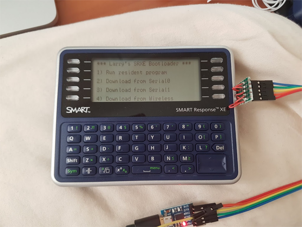
It all started with the acquisition by the author in the secondary market of an interesting device - Smart Response XE ( short description ). It is intended for schools: each student in the class receives a device similar to an electronic notebook or translator of the nineties, the teacher asks a question, and students dial on the device keyboards answers received over the radio (802.15.4) into a receiver connected to the teacher’s PC.
Support for these devices was discontinued several years ago, and the fact that schools purchased $ 100–200 apiece now pops up on eBay for 10 or less. "Iron" there is very suitable for geeks experiences:
')
- 60-key keyboard
- display with a resolution of 384x136, 2 bits per pixel - similar to BK, CGA, but 4 are not colors, but brightness gradations
- ATmega128RFA1 microcontroller (128 kB flash memory, 4 kB ROM, 16 kB RAM, 802.15.4 transceiver)
- external (with respect to the microcontroller, and not the entire device) flash memory of 1 megabyte (128 kilobytes) with SPI interface
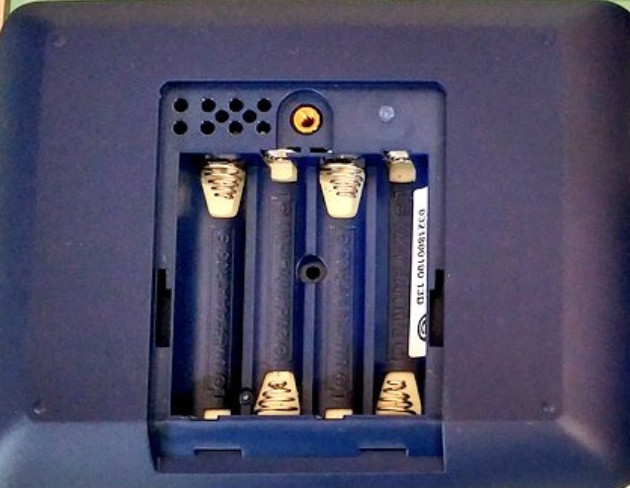
- compartment for 4 AAA elements.
By the name of the microcontroller, it is clear that it belongs to the AVR family, which means that making an Arduino-compatible device is more than a trivial task ...
From the news on Hackaday, the author found out that they already did it (using the same link, it tells you where to connect), having the opportunity to run games for Arduboy:
But the author is more interested in the opportunity not to play on the device, but to study:
- flash memory with SPI serial interface
- AVR loaders
- 802.15.4 standard
The author began by writing a library (GPL v3), which allows you to initialize the display, display text and rectangles, and gain access to flash memory with an SPI interface. Then he began to invent ideas for the practical use of the device: a pocket-sized VT-100-compatible terminal, multiplayer games. Redoing three devices, he decided to “teach” them to get sketches “through the air”. That would be not only interesting, but also very convenient: it is difficult to open the device case every time, and under the battery compartment cover there are only openings that allow you to connect a JTAG programmer to the board.
This is enough to fill the Arduino bootloader, but not the sketch - the serial port is not displayed there, you still can’t do without opening the case. Also, the TX0 and RX0 lines of the first serial port are combined with the lines for polling the keyboard matrix, namely, those that poll the function keys on the sides of the display. But what to do - the author built this:
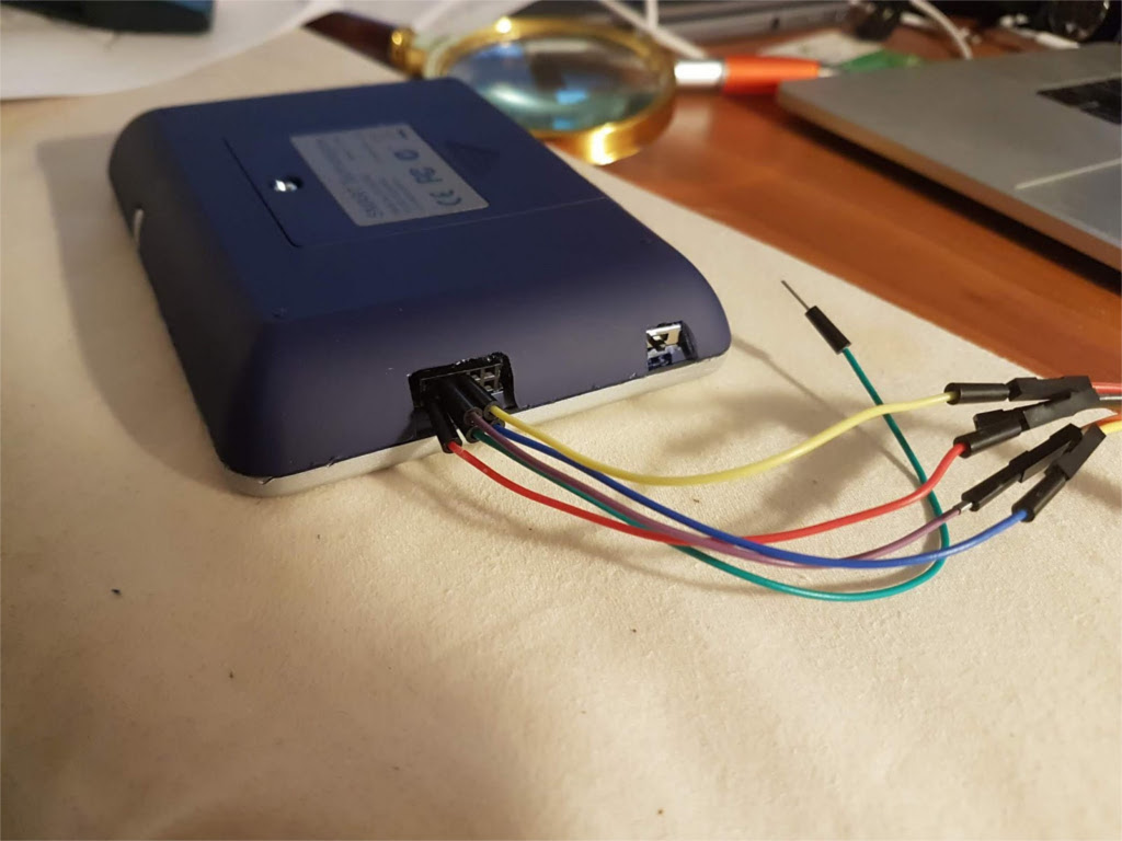
There he brought the JTAG lines, and now the battery compartment is not necessary to open. And so that it was possible to fill in and sketches, I brought out the same connector and both serial ports, adding also a switch, because it is impossible to physically turn off the device when the batteries are installed.
It took quite a long time to work with a soldering iron, stationery knife and glue gun. In general, it is much more convenient to fill in sketches “through the air”, it is necessary to reinvent something urgently for this.
Arduino IDE uses avrdude to fill in sketches. It communicates with the microcontroller using the STK500 protocol, which allows you to transfer files in both directions. It is poorly compatible with channels where variable delays, distortion and data loss are possible. If something goes away or rustles in the serial channel, you can go crazy looking for a reason. Once, the author suffered half a day until he realized that it was a bad cable, as well as a capricious converter of the CP2102 interface. Even a microcontroller with a built-in interface converter, for example, ATmega32u4, can sometimes be naughty. Each user of Arduino noticed that errors when filling sketches are not so rare. Sometimes the recording proceeds normally, and an error is detected during the verification reading. This does not mean that there was an error while writing - there was a failure while reading. Now imagine that when working "through the air" the same thing will happen, but much more often.
Having tried various ways to overcome this problem, the author came up with the following. The device has 128-kilobyte flash memory with SPI interface - we receive data by wire (remember that the author already has one device with a connector on the side), use this memory as a buffer, and send data to another device via radio. Such a greeting from Cybiko.
After writing the code for working with the radio channel, as well as the font, the bootloader became longer than 4 kilobytes. Therefore, the value of HFUSE had to be changed from 0xDA to 0xD8. Now the bootloader can be up to 8 kilobytes in length, and the starting address is 0x1E000. This is reflected in the Makefile, but must also be taken into account when uploading the bootloader using avrdude.
The 802.15.4 transceiver in the ATmega128RFA1 was originally designed to work using the ZigBee protocol, which is rather complicated, so the author decided instead to simply transfer packets. This is implemented in hardware in ATmega128RFA1, so it will take a bit of code. Also, for simplicity, the author decided to use a fixed channel, not allowing him to select it manually. The 802.15.4 standard supports 16 channels with numbers from 11 to 26. They are quite clogged, some also overlap WiFi channels (ZigBee channels are red, WiFi is blue, green and yellow).

It turned out that channels 15 and 26 are the least susceptible to interference from WiFi. The second of them was chosen by the author. Disclaimer: the translator does not know whether to simplify ZigBee so much. Maybe it is worth a little more programming and implement it completely?
On the first device, you need to implement a state machine that transmits data using the STK500 protocol. Most of the transmitted and received messages are self-sufficient, but some are tied to those that have passed through the channel earlier. A description of the dialogue is given here .
An important component of this dialogue is the transfer of packets intended for writing to the flash memory of the destination device. For simple AVR microcontrollers, the page size is 128 bytes, but for ATmega128RFA1 it is 256. And for the flash memory that is connected via SPI, it is the same. The program in the first device when pouring a sketch does not transfer it immediately to the second, but writes it to this memory. When the Arduino IDE verifies the correctness of the record, it sends what it has recorded there. Now it is necessary to transmit the received data over the air to the second device. In this case, switching from reception to transmission and back occurs quite often. The STK500 protocol is indifferent to delays, but it does not suffer data loss (strangely, but the above said that data transfer delays also have an effect). A loss in wireless transmission is inevitable. ATmega128RFA1 has a built-in hardware implementation of repeated requests with doubts about the correctness of the transfer, but the author decided to implement the same software independently. He developed a protocol in which much more data passes in one direction than the other.
It is not perfect, but everything works. 256-byte page is divided into four segments, each of which is transmitted over the radio as a packet. A packet holds up to 125 bytes of data plus one byte - length and two - CRC. So fragments of 64 bytes in length together with the numbers of pages and segments (from 0 to 3) are placed there. The receiving device has a variable that allows you to track how many segments are received, and when all four arrive, a confirmation is sent to the transmitting device that the entire page is received. No confirmation (CRC did not match) - send the whole page again. The speed at the same time turns out even more than when transmitting via cable. See:
But in general, it would be necessary to provide a convenient way to connect to the cable devices for pouring sketches and on it. For example, place an interface converter on the CP2102 inside, as in the photo, and glue it to the board so that it withstands the force when connecting and disconnecting the Micro USB cable.
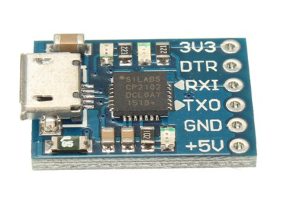
It also has a 3.3-volt stabilizer (and how to use it in a device with 6-volt power - if only there is the same stabilizer, and you can add two diodes to automatically choose which one will power the device). All three LEDs must be removed from the interface converter board, otherwise they will additionally load the batteries when working on them, and also interfere with the keyboard polling and working with flash memory with an SPI interface.
The pursuit of the goal was even more interesting than its achievement (and do not need that joke about the bus). The author has learned a lot about loaders for AVR, flash memory with SPI interface, STK500 protocol and 802.15.4 standard.
The rest of the code in addition to the library described above is here , and it is also under GPL v3. Author's twitter is here .
Source: https://habr.com/ru/post/447026/
All Articles