Universal Watchdog Timer on ATtiny13

The external watchdog timer is a crutch for bad developers who cannot develop a normally working program for microcontrollers or a stably working circuit.
Especially built-in WDT is available in most modern microcontrollers.
But there are cases when you have to deal with a finished board or module with certain problems. I made my first WDT to combat the rare, but nonetheless sometimes occurring hangs of ESP8266. And the software reset then did not save and the ESP-scale did not want to reconnect to WiFi. Distorting power to an external WDT solved the problem.
')
The second problem arose with the Elecrow ATMEGA 32u4 A9G GSM controller . There have been very rarely a hang-up of a SIM card. (By the way, the same problem happens with 3G and 4G USB modems). To combat such a hang, you need to distort the power to the SIM-ke. And it seems that there is even a GSM modem output for this, but this feature is not incorporated into the circuitry of the device. And in order to achieve maximum reliability, I had to turn again to an external guard dog.
The scheme on the timer 555 I did not repeat. Too many flaws in her revealed:
- Large size and quite a lot of strapping
- Inconvenient setting response time trimmer
- Quite a long reset time (capacitor discharge required)
- Well, the potential MK hangup with a low level at the output of the timer, when the timer simply stops working.
- And I did not find OpenSource projects on the Internet that fully meet my requirements.
New WDT Requirements
- Low price of the device, ease of manufacture and small dimensions
- Management of the periodic change of the logic level 0/1 at the input
- Simple setting of the response time (as an option, the choice of the preset intervals)
Iron design
I chose the ATtiny13 microcontroller as the main chip. His capacity was more than enough for my task. And the price, taking into account the reduction of the strapping elements, is almost the same as that of the 555 chip.

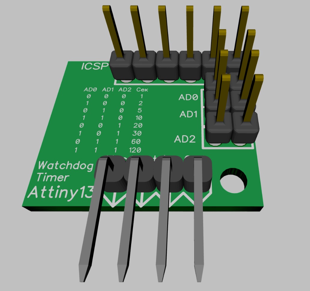
Five conclusions of MK (RESET decided not to touch) were distributed as follows:
- Timer output
- Reset input
- Three remaining pins - response times
P-channel MOSFET is used for power switching. Any one compatible with the body will do, but it is advisable to take it with the so-called “logical control level” - that is, fully opening from a low voltage of 3-5V: IRLML2502, AO3415, etc. Despite its small size, this transistor is able to control the load in 4A. If you need to switch something else, you can directly connect a 5V relay to this output.
The LED lights up when the timer is activated and the main device is turned off.
The main connector for connecting to the microcontroller board has four pins.
- Common bus
- Login - reset timer
- Output + 5V (controlled by timer)
- Input + 5V
Two connectors - ICSP programmer and power jumpers can be not installed on the board. The microcontroller should be flashed in the programmer in advance, and the response time should be set with a permanent jumper.
List of components
- MK Attiny13-SSU ~ $ 0.3 (with the purchase of 10 pieces)
- MOSFET P-channel IRLML5203 - $ 0.09 (order 50pcs) or MOSFET AO3415 - $ 0.05
- 1K SMD1206 resistor
- Resistor 470 SMD1206
- 1206 LED any color
- PLS-6, PLS-3 and PLS-4R connectors (PLD-3 and PLS-4R) are normally cut off from long combs
Manufacturing
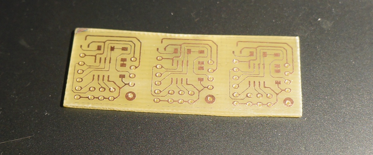
The boards turned out small - 18 × 22 mm. I spread two options:
For one-sided manufacturing LUT:

And for ordering in a factory with an improved design and transitions between the parties. (I will order from the Chinese, on occasion)


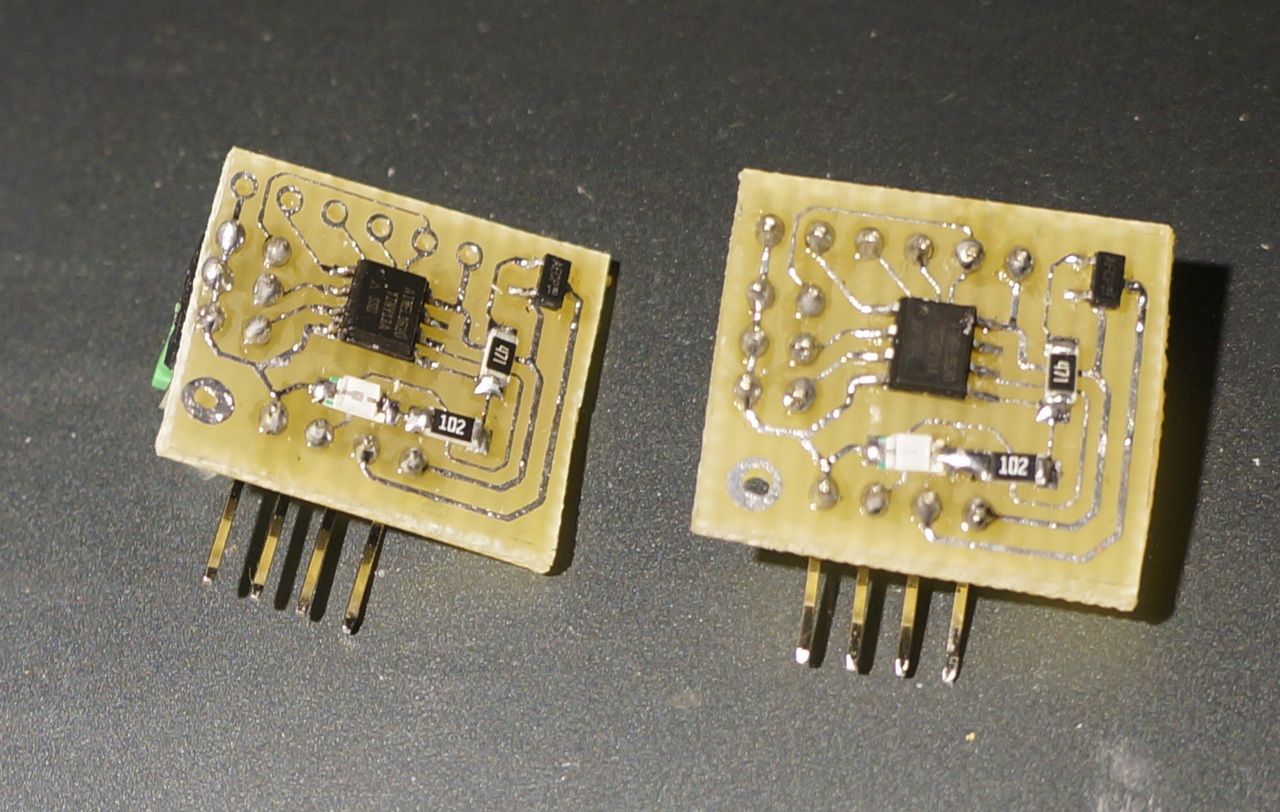
Home technologies give something like this prototype.

Firmware
For the firmware I used a homemade programmer on the bases Arduino Nano

I programmed in the Arduino IDE with Attiny13 - MicroCore support installed. The latest version of the IDE had problems with the ArduinoISP programmer, but it worked fine in the Arduino IDE 1.6.13 version. To understand that there the
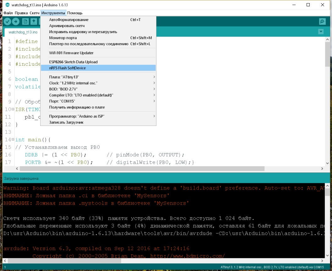
Tinku tuned to work from the internal resonator with a frequency of 1.2 MHz. The program is simple - we configure the inputs / outputs, read PB2 -PB4 and determine the response time, set the timer and go into IDLE mode. Interrupt the timer determine the status of the control input. If the state has changed to the opposite, reset the counter. If the meter reading has exceeded the set response time, we distort the output power.
#define F_CPU 1200000UL #include <avr/io.h> #include <util/delay.h> #include <avr/interrupt.h> boolean pb1_state; volatile uint16_t pb1_count; // TIMER0 ISR(TIM0_OVF_vect){ pb1_count++; } int main(){ // PB0 DDRB |= (1 << PB0); // pinMode(PB0, OUTPUT); PORTB &= ~(1 << PB0); // digitalWrite(PB0, LOW);} // PB1 DDRB &= ~(1 << PB1); // pinMode(PB1, INPUT_PULLUP); PORTB |= (1 << PB1); // PB2 DDRB &= ~(1 << PB2); // pinMode(PB2, INPUT_PULLUP); PORTB |= (1 << PB2); // PB3 DDRB &= ~(1 << PB3); // pinMode(PB3, INPUT_PULLUP); PORTB |= (1 << PB3); // PB4 DDRB &= ~(1 << PB4); // pinMode(PB4, INPUT_PULLUP); PORTB |= (1 << PB4); // PB2,PB3,PB4 ( ) (, = TM/4 ) uint16_t TM = 0; bool pb2 = false; bool pb3 = false; bool pb4 = false; if( PINB & (1 << PINB2) )pb2 = true; if( PINB & (1 << PINB3) )pb3 = true; if( PINB & (1 << PINB4) )pb4 = true; if( pb2 == true && pb3 == true && pb4 == true )TM = 4; // 1 else if( pb2 == false && pb3 == true && pb4 == true )TM = 8; // 2 else if( pb2 == true && pb3 == false && pb4 == true )TM = 20; // 5 else if( pb2 == false && pb3 == false && pb4 == true )TM = 40; // 10 else if( pb2 == true && pb3 == true && pb4 == false )TM = 80; // 20 else if( pb2 == false && pb3 == true && pb4 == false )TM = 120; // 30 else if( pb2 == true && pb3 == false && pb4 == false )TM = 240; // 60 else if( pb2 == false && pb3 == false && pb4 == false )TM = 480; // 120 pb1_count = 0; pb1_state = false; // ADC PRR = (1<<PRADC); // shut down ADC // TIMSK0 = (1<<TOIE0); // TIMER0 TCCR0B = (1<<CS02) | (1<<CS00); // 1/1024 // MCUCR &= ~(1<<SM1); // idle mode MCUCR &= ~(1<<SM0); // idle mode MCUCR |= (1<<SE); sei(); while(1) { // asm("sleep"); // TIMSK0 &= ~ (1<<TOIE0); // TIMER0 // PB1 bool pb1 = false; if( PINB & (1 << PINB1) )pb1 = true; // , if( pb1 != pb1_state )pb1_count = 0; pb1_state = pb1; // if( pb1_count >= TM ){ PORTB |= (1 << PB0); // digitalWrite(PB0, HIGH);} _delay_ms(1000); // PORTB &= ~(1 << PB0); // digitalWrite(PB0, LOW);} pb1_count = 0; // } TIMSK0 = (1<<TOIE0); // TIMER0 sei(); } return 0; } All code fit in 340 bytes - exactly one third of the kilobyte of memory. The timer operation is checked simply - depending on the installation time - the LED periodically lights up for 1 second. At this time, at the output of Vout, the voltage of 5V disappears. If the contact “input” with a frequency of 1 s is closed to ground - the reset is not performed and the LED does not light up.
The WDT control in the main program is as follows
#define PIN_WDT 5 //GPIO , WDT bool WDT_flag = false; // void WDT_begin(){ pinMode(PIN_WDT,OUTPUT); digitalWrite(PIN_WDT,WDT_FLAG); } // ( 1 WDT, ) void WDT_reset(){ if( WDT_flag)WDT_flag = false; else WDT_flag = true; digitalWrite(PIN_WDT,WDT_FLAG); } That's all. All source files, schemes and printed circuit boards can be downloaded from
Github
Source: https://habr.com/ru/post/447004/
All Articles