Breakuot-like game on PIC12F1572
The proposed design is proof that the NTSC color composite video signal can be generated using a very simple hardware.
Short description
Although it is more difficult to generate a color composite video signal in the NTSC system than a VGA, this requires fewer microcontroller pins (in this case, three combined by the simplest "mixer"). It is called composite because all information is transmitted in a single line. Lowercase and frame sync pulses, chrominance and luminance signals are combined together, in contrast to VGA, where each of these signals is separated by a separate wire. To send such a signal to a TV, one screened cable with “tulips” on both sides is enough.
')
There are only two active components in the device: a 28.636 MHz crystal oscillator (3.5795345 MHz x 8) and a PIC12F1572 microcontroller in a PDIP package.
The author decided to implement an analogue of the classic 1976 Breakout game, but in its place could be any arcade game, originally implemented on logic chips, since such games are fairly simple plots.
Now - more
If you think that you can not connect the device to a too modern TV without a yellow “tulip” - fortunately, you are mistaken. Look for a green “tulip” among those destined for YPbPr signals — you can also use composite there. Tested on two TVs, one of which is from RCA, the other - Toshiba.
How simple can a device that generates a composite NTSC video signal? See the diagram:
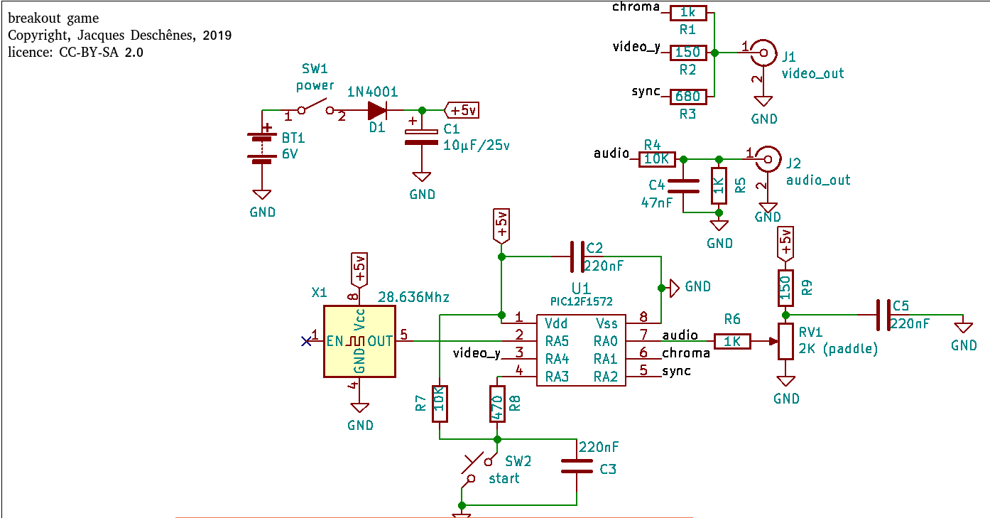
An external generator is needed to obtain a stable NTSC subcarrier frequency. It is eight times more than required. The microcontroller divides it into four, and therefore, operates at a frequency twice the frequency of the subcarrier. The device allows to receive six colors due to different combinations of four types of signals (logical unit, high-impedance state, subcarrier without phase shift, it is also with a phase shift of 180 °) on two terminals (the first is the output of the chrominance signal, the second is the output of the brightness signal):
Black - high-impedance state both there and there
White - high-impedance state and logical unit
Yellow - 180 ° subcarrier and logical unit
Magenta — unshifted subcarrier and logical unit
Blue - shiftless subcarrier and high-impedance state
Dark green - 180 ° offset subcarrier and high impedance state
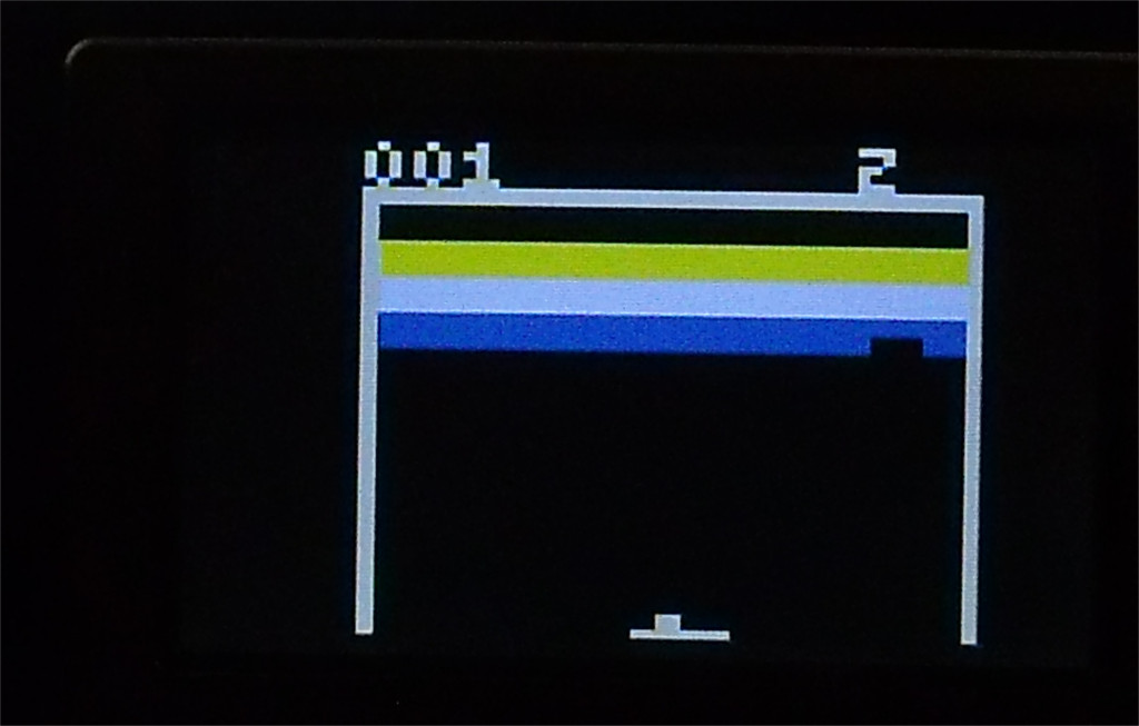
Dark green color on many televisions turns out indistinguishable from black, and therefore is not used. The author's camera doesn’t convey colors well, so the purple in the photo looks almost white:
The files are here under GPL v3.
The code is written in assembler, out of two kilograms of ROM (in PIC microcontrollers, ROM does not store bytes, but words with a width different from 8 bits) 54% are involved, and out of 256 bytes of RAM, 63%. The video was shot with the same camera, and the purple again merges with the white:
A brief history of the Breakout game is given in Wikipedia .
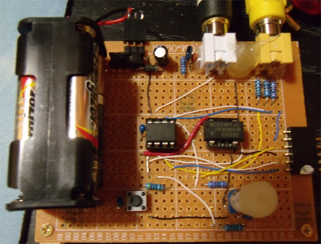
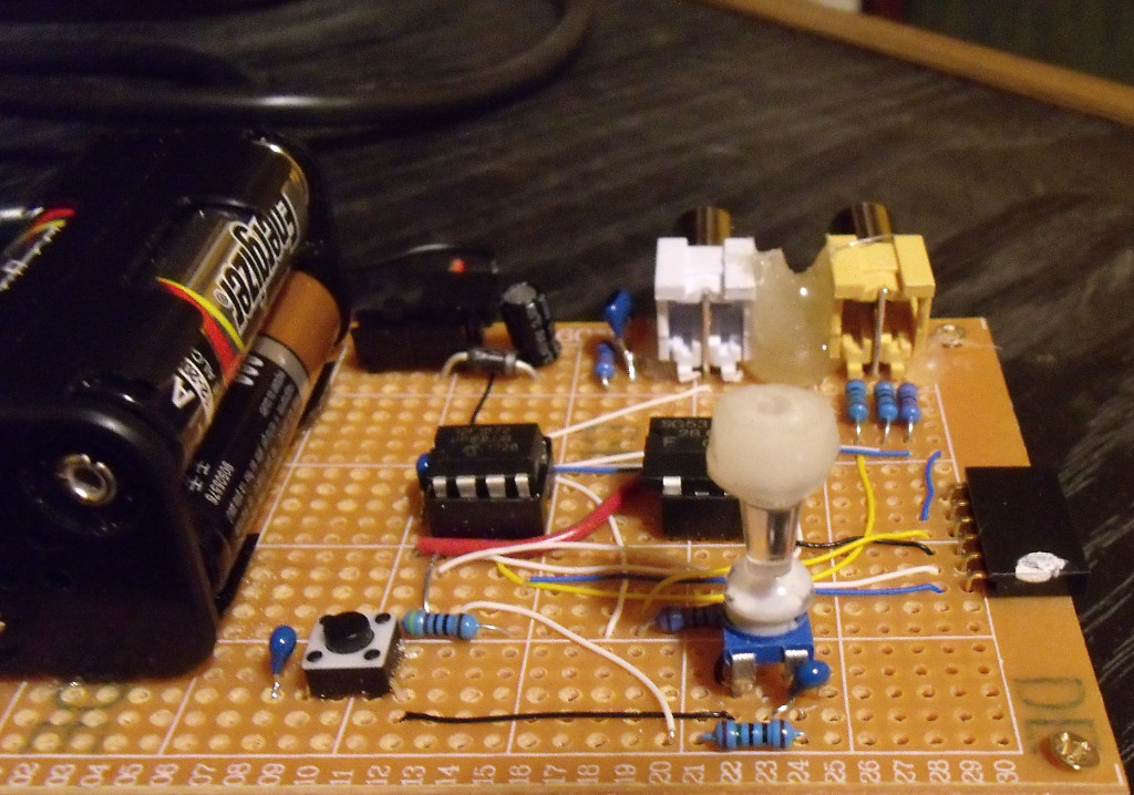
The author made a mini-miniature joystick by gluing a power pushpin to a trimmer resistor. He rustles a lot, which makes it difficult to play, so it is better to use a variable resistor and a pen to it of normal size.
From the translator: in this circuit, the same microcontroller pin is used for both audio output and for receiving an analog signal from a joystick. Probably, for this, it is programmatically switched at the right moments from the mode of entering into the mode of output and back. In order for the constant component not to hit the TV, it is recommended to put a capacitor in front of the “tulip”.
Source: https://habr.com/ru/post/446978/
All Articles