Lighting is harmful, or how to save the charge of the car battery
I continue the cycle of articles devoted to cycling in the field of low-voltage power circuit control. This time I’ll tell you about a device that prevents a car battery from being deeply discharged by various secondary consumers.
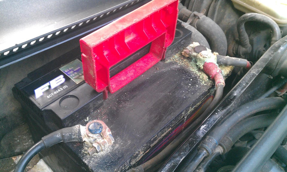
One of the possible consequences of an uncontrolled discharge.
Buying a first car or motorcycle is a significant milestone in the life of every person, and especially the engineer. After all, who else besides the obvious advantages of his new iron horse immediately draws attention to its non-obvious drawbacks? Who immediately begins to think about all sorts of improvements and additions to the standard equipment? Of course, if this is a car from the upper segment, and even a “fashionable” brand, then at first it may seem that there is absolutely everything in it. But as practice shows, in this case time refutes the first impressions. If you buy an economy class car, then your hands begin to itch literally on the very first day!
The desire to maximally “stuff” your car with various auxiliary electronic devices is quite natural. However, soon after the implementation of all these plans, life confronts the car owner with the harsh reality. It turns out that even the most modern, built on the latest elemental base, the device is still pretty eager for electricity. And the seemingly so huge automobile battery is not a nuclear reactor at all and can easily “sit down” under the weight of all these seemingly innocuous consumers in a matter of days.
')
In order not to spread further with abstract and hypothetical situations, I will go straight to my own history. After buying a car, the first was the desire to put a registrar in it. This was done within the shortest possible period, almost completely dictated by the speed of delivery of the package from Aliexpress. It is clear that regular power supply from the cigarette lighter was extremely inconvenient, and the recorder quickly received a stationary connection to the nearest onboard power line via a 12 / 5v switching converter. And since the matter was, to put it mildly, not yesterday, this converter was not like modern, for its own needs, as it turned out later, it ate as much as 21 mA of current. Now let us estimate how much this converter alone could feed a new and fully charged battery with a capacity of 60 Ah. Arithmetic is extremely simple and disappointing.

So for less than four months, the converter, which is not loaded with anything, will drop the battery literally “to zero”. If we take into account that the capacity of a not quite fresh battery can easily be widowed less, and the charge after city rides is far from 100%, a rainy day easily comes after a month with a hook.
And this is all, I repeat, only the voltage converter. Yes, today you can buy a converter that takes only half a milliampere for your own needs, but I gave an example just to show how slowly and confidently thewater wears away a stone, even a trifling, but constantly acting, consumer drains energy out of such a huge battery
We go further, the recorder itself in FHD @ 30fps recording mode consumes almost 300 mA from a + 5v source, which, after conversion taking into account efficiency, yields about 150 mA of current from the on-board network. Let us assume that the converter is replaced by a modern one, and we calculate the discharge time only by this current.

Just over two weeks, but in practice - ten days. Now the prospect of lighting (and possibly changing the battery) looms unwittingly after the next vacation or business trip.
So it happened to me: when I left for a small forced vacation, I did not think that after a week or so even the central lock could not open the door for me.
Many will say that he himself is to blame, that everything must be de-energized, or, at least, to stop recording, and they will be right. But life is life, and memory is no longer the same, and how long a trifling hospital will last will not always be known in advance. Therefore, the idea of a circuit breaker immediately appeared.
There is, of course, an option to power the recorder from the ignition switch, so that it only works on the move, but this option is also not very good, because If the car hit in the parking lot, I would like to have a chance to see the culprit. Plus, after a short time after installing the recorder, the car was added with several more devices, including a hidden GPS tracker that should work if not to the bitter end, then at least until the moment when “almost everything” is already.
In general, within a few weeks of passive thinking, the idea of a device that should monitor the voltage of the on-board network and on the basis of this data manage the power supply to two groups of consumers: the secondary ones (recorder, USB socket) and the main ones (GPS tracker and some more) finally took shape. what).
The first virtual prototypes of the device were “built” on the basis of the LM393N analog comparators and were able to do everything that was originally planned to receive from the device. Abstract scheme was obtained approximately as follows.
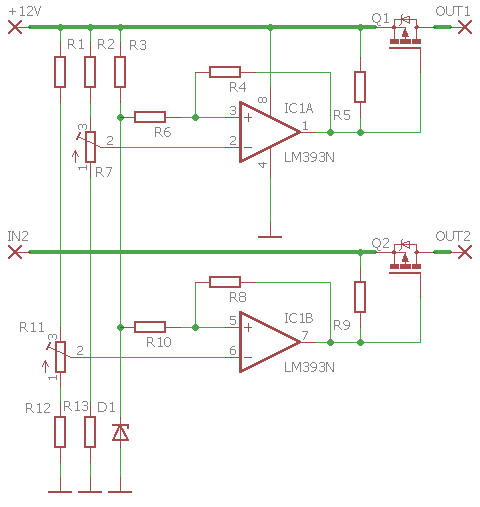
Here two comparators are used for switching loads. General generator of the reference voltage, two dividers, determining the response thresholds, piping of comparators, two power switches. External strapping of the finished device is planned as follows.
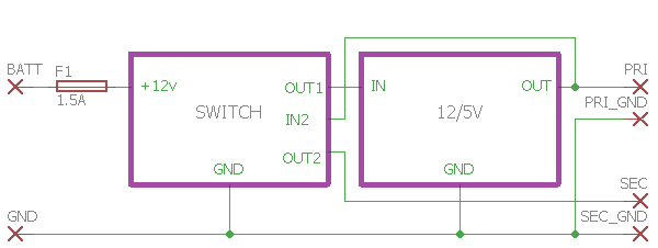
The primary key is kept on longer than the secondary key, so the downconverter itself is powered through it. Directly connected to the converter primary load. The secondary key switches the secondary loads already in the + 5v circuit at the output of the converter.
It seems to be all that is needed, but, as is often the case, as we think about the details, ideas for alternative implementations have emerged. First, the analog circuit contained a decent mountain of discrete elements providing comparators' operating modes, second, setting off thresholds is assumed using trimming resistors, which complicates tuning and creates the likelihood of "shaking" from jolting and time. Therefore, in the end, it was decided to dwell on the digital implementation, which turned out to be much simpler and schematic and customizable, opening up enormous opportunities for improving the control algorithm, and, most importantly in this context, turned out to be an order of magnitude more economical in terms of current consumption.
As the heart of the device, the ATtiny13A controller, which, apart from simplicity and cheapness, is still being produced, is still being produced in a warm Dip package for the oldfaga. Initially, the capabilities of even such a small controller seemed redundant on all fronts, from the number of inputs / outputs to the amount of software and RAM, however, the appetite, as you know, comes with eating. As a result, looking ahead, I will say that in the final version, all the outputs of the microcircuit were in the case, and no more than two dozen bytes remained of the free program memory.
To measure the voltage of the on-board network, the microcontroller required only one input, which is linked to the ADC. Two more logical outputs were to control consumers. First of all, after the final mental transition to the “figure”, there was a desire to adapt two free GPIOs to the task, and the decision was not long in coming. When once again in the cold the starter turned the engine with a poorly concealed strain, the presence of a thermal sensor in the circuit and algorithm seemed very useful. As a result, the second ADC was used to measure the temperature. And so that the thermistor consumes current only when it is needed, it was decided to power it from the last remaining logic output.
As a result, the scheme of the device has acquired such a final look.
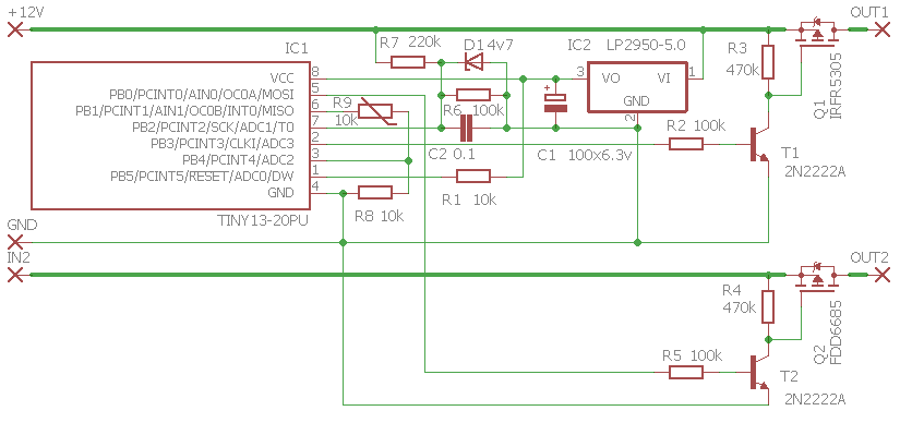
Here we see the very minimum of details, and among them nothing is subject to any kind of “twisting”. Let us run briefly on the main points.
To power the controller, you need a stable voltage from 1.8 to 5.5 V, which means that the circuit must have a stabilizer, which will lower the voltage of the on-board network to the required level. From the point of view of energy saving, it may seem that there is a place exclusively for the pulse stepdown converter, but this is only at first glance. The fact is that ATtiny13A even in the very energy-intensive mode of operation (frequency 8 MHz, active code execution) consumes no more than 6 mA. In this scheme, the controller is 99% of the time in deep sleep mode and also operates at a frequency of 1.2 MHz, with the result that the average consumption is approximately less than 15 μA. Plus approximately 80 µA per base current of the driving transistors (if both loads are included). Well, for a small fraction of a second, the power of the thermistor is activated, which adds about 25 microamps to the average current. And the answer to the question “Is it worth it for the load with a consumption of no more than 120 µA to fence a pulse converter?” Seems not so straightforward. And if we consider that we are dealing with analog measurements, then definitely not worth it. Therefore, a linear stabilizer LP2950 was used, a functional analogue of the popular 78L05, but much more economical. This converter can produce up to 100 mA of output current, while consuming up to 75 µA of a loved one.
The voltage divider of the on-board network, protected by a zener diode and a capacitor, allows to measure voltages up to 15 V.
The output resistance of the divider is ten times higher than the recommended 10 kΩ for the ADC signal source, but thanks to capacitor C2, measurement problems do not arise.
A divider with a thermistor due to the presence of a controlled power source is built using the recommended ratings. NTCLE100E3 is used as a sensor, but there are no limitations, you can use any thermistor of approximately the same rating, the main thing is to make adjustments to the source code constants corresponding to its characteristics so that the voltage of the divider is converted to the correct temperature value.
As control keys, power P-channel MOSFETs of any type with acceptable open channel resistance and maximum drain-source voltage of at least 30 volts are used. The above circuit uses different transistors. This is done because they have to switch different voltages and the type of each of them was chosen for specific working conditions. The upper transistor should be more high-voltage, and the lower should have as little as possible an open channel resistance. But, I repeat, this decision is dictated by the device switching circuit (see above), with other switching on the requirements for the lower transistor may be different.
To control the power switches used a pair of identical bipolar transistors. At first, it may seem that these transistors are superfluous, but not everything is so simple. Insulated gate field-effect transistors begin to open not from any voltage of the required polarity on the gate, but only after reaching a certain threshold level, which appears in datasheets under the name “gate-to-source threshold voltage” and is usually equal to 2..4 V. Now let's just count. The output circuit of the controller can form two logical levels: a logical "0" with a voltage tending to zero; and logical "1" with voltage aspiring to the supply. When powered at 5 volts, these will be voltages of about 0 and 5 V, respectively. As a result, when switching a 12-volt source, a logical "0" on the gate will create a voltage difference source-gate 12 - 0 = 12 volts, the power transistor is open. It seems everything is normal, but the logical “1” with its voltage of 5 V will create a voltage of 12 - 5 = 7 volts between the source and the gate, and the power transistor will still remain open. Thus, a five-volt control signal cannot control a key that commutes a voltage higher than 7..9 volts. Therefore, control bipolar transistors actually work not so much with signal switches, as with amplifiers that raise the control voltage from 5 volts to the voltage of the on-board network.
The resistor in the base circuit of each of the control transistors simply limits the current of the controller outputs to a level sufficient to control. Their nominal values can be reduced by two or three times with no effect on the operation of the circuit.
It must be said that limiting the threshold voltage of a power MOSFET works not only towards high voltages, as mentioned above, but also towards low voltages. After all, if the minimum opening voltage of the transistor is, say, 4 volts, then when switching a 3.3 V source, even connecting the gate to the ground does not create the desired voltage difference between the source and the gate, and the transistor will remain closed. So 5 volts is perhaps the minimum voltage that can be switched by the selected transistors reliably.
Device setup is a separate conversation. On the one hand, there is not a single setting element in the scheme, but on the other hand, we are dealing with the measurement of stresses with an accuracy not worse than 0.1 V. How to connect all this? There are two ways. The first is the use of resistors R6, R7 and R8 with a tolerance not worse than 1% (and better than 0.1%). The second involves the use of conventional resistors with the measurement of their real resistance and correction coefficients in the source code of the program.
The first method is good for mass production, but it is much more attractive for us not to bother with finding the right high-precision nominal values, so let's take the second way. You can measure resistance using a conventional multimeter, its accuracy is quite enough here. Another object of measurement will be the voltage of the stabilizer supplying the circuit. The ADC of the controller can operate in different modes, but for a number of reasons it is more convenient for us to use one in which the digital conversion result is read off relative to the supply voltage. That is why it is important to know him as accurately as possible.
The calculation is extremely simple and consists of calculating the division ratio of the resistive divider and the proportion of transferring the result to LSB for analog-to-digital conversion.

Ux is the input voltage of the divider;
Ru is the resistance of the upper arm of the divider (to which Ux is supplied);
Rd is the resistance of the lower arm of the divider (which is connected to ground);
Uref is the reference voltage of the ADC (i.e., the controller supply voltage);
1024 - the number of discrete values at the output of a 10-bit ADC;
LSB is the numeric value received by the program from the ADC.
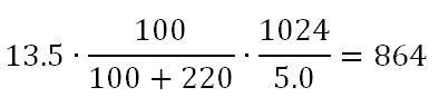
Let's start with the voltage divider R6-R7. For example, let's take real resistances completely corresponding to those indicated in the diagram. Power, too, take exactly 5.0 V. An example of calculating the results of a voltage conversion of 13.5 volts:
With due accuracy of measurement of the initial values, the result is quite accurate in order not to adjust it in field tests, but to use as is.
The formula for calculating a divider that measures temperature is basically no different; only the variable will be Ru, and Ux can be taken equal to Uref. The result will look like this:

For example, take the value of R8 from the circuit, and R9 from the datasheet to NTCLE100E3 at a temperature of 0⁰C:
The resistance of the thermistor at different temperatures can be found in the datasheet, but it is better, of course, to measure them yourself. The latter may present some problem, therefore, as a compromise, I propose to measure the real resistance at one temperature and thus find the correction factor for resistance at all other temperatures from the datasheet. Most thermistors have a more or less linear dependence of resistance on temperature, so this method can be considered quite reliable.
Actually, all the constants in the program are calculated based on the assumption that the real values fully comply with the scheme, in case the parts with small tolerances will be used.
The complete project archive for AtmelStudio (compiler gcc-avr 5.4.0) can be downloaded here , also laid out the already assembled hex . And under the cut listing of the source file, not to go far.
. , – , – . , . :
, .
. , . , , .
, . , , , 12.5 , , 12.4 . . , .


, , , . , . «» 8-9 .
+50⁰C . , , , . .
«», , (watchdog). .
. 1006 , - .
.
One of the possible consequences of an uncontrolled discharge.
Buying a first car or motorcycle is a significant milestone in the life of every person, and especially the engineer. After all, who else besides the obvious advantages of his new iron horse immediately draws attention to its non-obvious drawbacks? Who immediately begins to think about all sorts of improvements and additions to the standard equipment? Of course, if this is a car from the upper segment, and even a “fashionable” brand, then at first it may seem that there is absolutely everything in it. But as practice shows, in this case time refutes the first impressions. If you buy an economy class car, then your hands begin to itch literally on the very first day!
The desire to maximally “stuff” your car with various auxiliary electronic devices is quite natural. However, soon after the implementation of all these plans, life confronts the car owner with the harsh reality. It turns out that even the most modern, built on the latest elemental base, the device is still pretty eager for electricity. And the seemingly so huge automobile battery is not a nuclear reactor at all and can easily “sit down” under the weight of all these seemingly innocuous consumers in a matter of days.
')
In order not to spread further with abstract and hypothetical situations, I will go straight to my own history. After buying a car, the first was the desire to put a registrar in it. This was done within the shortest possible period, almost completely dictated by the speed of delivery of the package from Aliexpress. It is clear that regular power supply from the cigarette lighter was extremely inconvenient, and the recorder quickly received a stationary connection to the nearest onboard power line via a 12 / 5v switching converter. And since the matter was, to put it mildly, not yesterday, this converter was not like modern, for its own needs, as it turned out later, it ate as much as 21 mA of current. Now let us estimate how much this converter alone could feed a new and fully charged battery with a capacity of 60 Ah. Arithmetic is extremely simple and disappointing.
So for less than four months, the converter, which is not loaded with anything, will drop the battery literally “to zero”. If we take into account that the capacity of a not quite fresh battery can easily be widowed less, and the charge after city rides is far from 100%, a rainy day easily comes after a month with a hook.
And this is all, I repeat, only the voltage converter. Yes, today you can buy a converter that takes only half a milliampere for your own needs, but I gave an example just to show how slowly and confidently the
We go further, the recorder itself in FHD @ 30fps recording mode consumes almost 300 mA from a + 5v source, which, after conversion taking into account efficiency, yields about 150 mA of current from the on-board network. Let us assume that the converter is replaced by a modern one, and we calculate the discharge time only by this current.
Just over two weeks, but in practice - ten days. Now the prospect of lighting (and possibly changing the battery) looms unwittingly after the next vacation or business trip.
So it happened to me: when I left for a small forced vacation, I did not think that after a week or so even the central lock could not open the door for me.
Many will say that he himself is to blame, that everything must be de-energized, or, at least, to stop recording, and they will be right. But life is life, and memory is no longer the same, and how long a trifling hospital will last will not always be known in advance. Therefore, the idea of a circuit breaker immediately appeared.
There is, of course, an option to power the recorder from the ignition switch, so that it only works on the move, but this option is also not very good, because If the car hit in the parking lot, I would like to have a chance to see the culprit. Plus, after a short time after installing the recorder, the car was added with several more devices, including a hidden GPS tracker that should work if not to the bitter end, then at least until the moment when “almost everything” is already.
In general, within a few weeks of passive thinking, the idea of a device that should monitor the voltage of the on-board network and on the basis of this data manage the power supply to two groups of consumers: the secondary ones (recorder, USB socket) and the main ones (GPS tracker and some more) finally took shape. what).
How could this be done
The first virtual prototypes of the device were “built” on the basis of the LM393N analog comparators and were able to do everything that was originally planned to receive from the device. Abstract scheme was obtained approximately as follows.
Here two comparators are used for switching loads. General generator of the reference voltage, two dividers, determining the response thresholds, piping of comparators, two power switches. External strapping of the finished device is planned as follows.
The primary key is kept on longer than the secondary key, so the downconverter itself is powered through it. Directly connected to the converter primary load. The secondary key switches the secondary loads already in the + 5v circuit at the output of the converter.
What happened in the end
It seems to be all that is needed, but, as is often the case, as we think about the details, ideas for alternative implementations have emerged. First, the analog circuit contained a decent mountain of discrete elements providing comparators' operating modes, second, setting off thresholds is assumed using trimming resistors, which complicates tuning and creates the likelihood of "shaking" from jolting and time. Therefore, in the end, it was decided to dwell on the digital implementation, which turned out to be much simpler and schematic and customizable, opening up enormous opportunities for improving the control algorithm, and, most importantly in this context, turned out to be an order of magnitude more economical in terms of current consumption.
As the heart of the device, the ATtiny13A controller, which, apart from simplicity and cheapness, is still being produced, is still being produced in a warm Dip package for the oldfaga. Initially, the capabilities of even such a small controller seemed redundant on all fronts, from the number of inputs / outputs to the amount of software and RAM, however, the appetite, as you know, comes with eating. As a result, looking ahead, I will say that in the final version, all the outputs of the microcircuit were in the case, and no more than two dozen bytes remained of the free program memory.
To measure the voltage of the on-board network, the microcontroller required only one input, which is linked to the ADC. Two more logical outputs were to control consumers. First of all, after the final mental transition to the “figure”, there was a desire to adapt two free GPIOs to the task, and the decision was not long in coming. When once again in the cold the starter turned the engine with a poorly concealed strain, the presence of a thermal sensor in the circuit and algorithm seemed very useful. As a result, the second ADC was used to measure the temperature. And so that the thermistor consumes current only when it is needed, it was decided to power it from the last remaining logic output.
As a result, the scheme of the device has acquired such a final look.
Here we see the very minimum of details, and among them nothing is subject to any kind of “twisting”. Let us run briefly on the main points.
To power the controller, you need a stable voltage from 1.8 to 5.5 V, which means that the circuit must have a stabilizer, which will lower the voltage of the on-board network to the required level. From the point of view of energy saving, it may seem that there is a place exclusively for the pulse stepdown converter, but this is only at first glance. The fact is that ATtiny13A even in the very energy-intensive mode of operation (frequency 8 MHz, active code execution) consumes no more than 6 mA. In this scheme, the controller is 99% of the time in deep sleep mode and also operates at a frequency of 1.2 MHz, with the result that the average consumption is approximately less than 15 μA. Plus approximately 80 µA per base current of the driving transistors (if both loads are included). Well, for a small fraction of a second, the power of the thermistor is activated, which adds about 25 microamps to the average current. And the answer to the question “Is it worth it for the load with a consumption of no more than 120 µA to fence a pulse converter?” Seems not so straightforward. And if we consider that we are dealing with analog measurements, then definitely not worth it. Therefore, a linear stabilizer LP2950 was used, a functional analogue of the popular 78L05, but much more economical. This converter can produce up to 100 mA of output current, while consuming up to 75 µA of a loved one.
The voltage divider of the on-board network, protected by a zener diode and a capacitor, allows to measure voltages up to 15 V.
I know that now a wave of criticism for such a decision will fall upon me, but we will be objective. Firstly, I’m not developing a satellite, and secondly, there is no such single factor that would lead to a catastrophe. The resistance of the shoulders is high, the zener diode is able to divert much more current than the one that can flow through the divider even in the most pessimistic scenario. From high-frequency pulses, when the Zener diode does not have enough speed, it protects the capacitor C2 (with a resistor R7 creates a low-pass filter with a cut-off frequency of just 7 Hz). D1 and R6 to some extent insure the scheme from dumping each other. And about linearity we should not forget, any method of galvanic isolation in such a place would make a theoretical calculation of values completely unrealistic, we will have to calibrate at least a prototype, but we don’t need it.
The output resistance of the divider is ten times higher than the recommended 10 kΩ for the ADC signal source, but thanks to capacitor C2, measurement problems do not arise.
In general, the input resistance of the AVR controllers of AVR controllers is not less than 100 MΩ according to the datasheet. However, nevertheless, the same datasheet recommends using sources with an internal resistance of up to 10 kΩ. Why is that? The matter is in the principle of operation of this very ADC. The converter itself works on the principle of a successive approximation , and its input circuit is a low-pass filter from a resistor and a capacitor. Obtaining a 10-bit sample is performed iteratively and it is necessary that during the entire measurement time the capacitor is charged to the full measured voltage. If the output impedance of the source is too large, the capacitor will continue to charge directly during the conversion process and the result will be inaccurate. In our case, the capacity of C2 is more than seven thousand times greater than the capacity of the ADC filter, which means that when the charge is redistributed between these capacitors when they are switched on in parallel at the time of measurement, the input voltage will decrease by no more than 1/7000, which is seven times less than the 10-bit ADC limit accuracy. However, you need to keep in mind that such a trick works only for single measurements with significant pauses between them, so you should not “improve” the control program by adding a cycle to it for several consecutive measurements with averaging the result.
A divider with a thermistor due to the presence of a controlled power source is built using the recommended ratings. NTCLE100E3 is used as a sensor, but there are no limitations, you can use any thermistor of approximately the same rating, the main thing is to make adjustments to the source code constants corresponding to its characteristics so that the voltage of the divider is converted to the correct temperature value.
As control keys, power P-channel MOSFETs of any type with acceptable open channel resistance and maximum drain-source voltage of at least 30 volts are used. The above circuit uses different transistors. This is done because they have to switch different voltages and the type of each of them was chosen for specific working conditions. The upper transistor should be more high-voltage, and the lower should have as little as possible an open channel resistance. But, I repeat, this decision is dictated by the device switching circuit (see above), with other switching on the requirements for the lower transistor may be different.
To control the power switches used a pair of identical bipolar transistors. At first, it may seem that these transistors are superfluous, but not everything is so simple. Insulated gate field-effect transistors begin to open not from any voltage of the required polarity on the gate, but only after reaching a certain threshold level, which appears in datasheets under the name “gate-to-source threshold voltage” and is usually equal to 2..4 V. Now let's just count. The output circuit of the controller can form two logical levels: a logical "0" with a voltage tending to zero; and logical "1" with voltage aspiring to the supply. When powered at 5 volts, these will be voltages of about 0 and 5 V, respectively. As a result, when switching a 12-volt source, a logical "0" on the gate will create a voltage difference source-gate 12 - 0 = 12 volts, the power transistor is open. It seems everything is normal, but the logical “1” with its voltage of 5 V will create a voltage of 12 - 5 = 7 volts between the source and the gate, and the power transistor will still remain open. Thus, a five-volt control signal cannot control a key that commutes a voltage higher than 7..9 volts. Therefore, control bipolar transistors actually work not so much with signal switches, as with amplifiers that raise the control voltage from 5 volts to the voltage of the on-board network.
The resistor in the base circuit of each of the control transistors simply limits the current of the controller outputs to a level sufficient to control. Their nominal values can be reduced by two or three times with no effect on the operation of the circuit.
It is easy to see that the control transistors were not in the analog circuit based on LM393N. The whole point is that the output stage of the selected comparator is built according to the open collector scheme, that is, its output is simply the output of the terminal transistor collector. Such a construction principle requires additional details to be mounted on the microchip to create the output stage load, but on the other hand it makes the microcircuit very flexible. An open collector allows the comparator to control any permissible current source, and not only compatible with that which provides power to the comparator itself.
It must be said that limiting the threshold voltage of a power MOSFET works not only towards high voltages, as mentioned above, but also towards low voltages. After all, if the minimum opening voltage of the transistor is, say, 4 volts, then when switching a 3.3 V source, even connecting the gate to the ground does not create the desired voltage difference between the source and the gate, and the transistor will remain closed. So 5 volts is perhaps the minimum voltage that can be switched by the selected transistors reliably.
Customization
Device setup is a separate conversation. On the one hand, there is not a single setting element in the scheme, but on the other hand, we are dealing with the measurement of stresses with an accuracy not worse than 0.1 V. How to connect all this? There are two ways. The first is the use of resistors R6, R7 and R8 with a tolerance not worse than 1% (and better than 0.1%). The second involves the use of conventional resistors with the measurement of their real resistance and correction coefficients in the source code of the program.
The first method is good for mass production, but it is much more attractive for us not to bother with finding the right high-precision nominal values, so let's take the second way. You can measure resistance using a conventional multimeter, its accuracy is quite enough here. Another object of measurement will be the voltage of the stabilizer supplying the circuit. The ADC of the controller can operate in different modes, but for a number of reasons it is more convenient for us to use one in which the digital conversion result is read off relative to the supply voltage. That is why it is important to know him as accurately as possible.
The calculation is extremely simple and consists of calculating the division ratio of the resistive divider and the proportion of transferring the result to LSB for analog-to-digital conversion.
Ux is the input voltage of the divider;
Ru is the resistance of the upper arm of the divider (to which Ux is supplied);
Rd is the resistance of the lower arm of the divider (which is connected to ground);
Uref is the reference voltage of the ADC (i.e., the controller supply voltage);
1024 - the number of discrete values at the output of a 10-bit ADC;
LSB is the numeric value received by the program from the ADC.
Let's start with the voltage divider R6-R7. For example, let's take real resistances completely corresponding to those indicated in the diagram. Power, too, take exactly 5.0 V. An example of calculating the results of a voltage conversion of 13.5 volts:
With due accuracy of measurement of the initial values, the result is quite accurate in order not to adjust it in field tests, but to use as is.
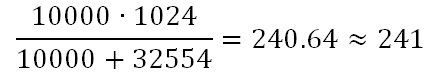
The formula for calculating a divider that measures temperature is basically no different; only the variable will be Ru, and Ux can be taken equal to Uref. The result will look like this:
For example, take the value of R8 from the circuit, and R9 from the datasheet to NTCLE100E3 at a temperature of 0⁰C:
If someone says that under the influence of the load from the series-connected R8 and R9, the voltage at the logic output can subside, then of course he will be right. In theory. And in practice, even the most pessimistic scenario, when the resistance of R9 thermistor will be equal to zero, the consumption from the controller output will be no more than 0.5 mA, which will not cause any noticeable drop. At least, in the course of field tests, this fall could not be recorded with a voltmeter having an accuracy of 0.01 V.
The resistance of the thermistor at different temperatures can be found in the datasheet, but it is better, of course, to measure them yourself. The latter may present some problem, therefore, as a compromise, I propose to measure the real resistance at one temperature and thus find the correction factor for resistance at all other temperatures from the datasheet. Most thermistors have a more or less linear dependence of resistance on temperature, so this method can be considered quite reliable.
Actually, all the constants in the program are calculated based on the assumption that the real values fully comply with the scheme, in case the parts with small tolerances will be used.
Firmware
The complete project archive for AtmelStudio (compiler gcc-avr 5.4.0) can be downloaded here , also laid out the already assembled hex . And under the cut listing of the source file, not to go far.
Source code
: L:0x6A, H:0xFF.
//#define F_CPU 1200000UL //
#include <avr/io.h>
#include <avr/wdt.h>
#include <avr/sleep.h>
#include <avr/interrupt.h>
#include <util/delay.h>
//#define DBG
#define TEMPERATURE_OVERHEAT 753 // LSB- +50⁰C
#define TEMPERATURE_GIST 8 // ( LSB)
#define VOLTAGE_GIST 3 // ( LSB)
#define INTERVAL WDTO_1S // (1 )
#ifndef DBG
#define CELL_CHANGE_TIMEOUT 90 // ( INTERVAL, 254)
#define OVERHEAT_TIMEOUT 300 // "" ( INTERVAL)
#else
#define CELL_CHANGE_TIMEOUT 2
#define OVERHEAT_TIMEOUT 3
#endif
typedef unsigned char bool; //
#define true 0 == 0 //
#define false 0 != 0 //
typedef enum {st_none = 0b00, st_primary = 0b01, st_secondary = 0b10, st_both = 0b11} t_states; //
// ,
typedef enum {adc_temperature, adc_voltage} t_measure; //
typedef enum {move_null, move_up, move_down} t_movement; //
//
struct t_coordidates {
signed char row, col;
};
//
struct t_correction {
t_movement voltage, temperature;
};
#define CELLS_ROWS 3 // ( )
#define CELLS_COLS 5 // ( )
//
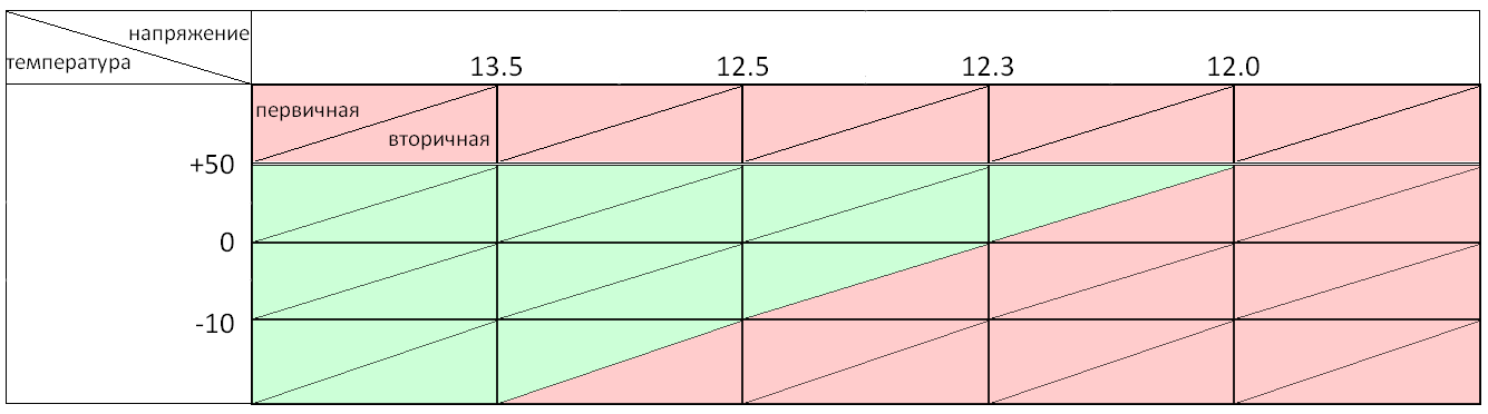
const t_states CELLS[CELLS_ROWS][CELLS_COLS] = {
{st_both, st_both, st_both, st_primary, st_none},
{st_both, st_both, st_primary, st_none, st_none},
{st_both, st_primary, st_none, st_none, st_none}
};
// LSB- ,
const unsigned int ROWS_EDGES[CELLS_ROWS - 1] = {
241, // 0⁰C
157 // -10⁰C
};
// LSB- ,
const unsigned int COLS_EDGES[CELLS_COLS - 1] = {
864, // 13.5V
800, // 12.5V
787, // 12.3V
768 // 12.0V
};
unsigned int overheat_rest_time = 0; // ""
unsigned char cell_change_time = 0; //
unsigned char no_cur_cell_time = 0; // ,
#define NULL_CELL (struct t_coordidates){.col = -1, .row = -1} // ,
#define NULL_CORRECTION (struct t_correction){.voltage = move_null, .temperature = move_null} // ,
struct t_correction moved_from = NULL_CORRECTION; //
struct t_coordidates cur_cell = NULL_CELL, //
next_cell = NULL_CELL; // -
//
static void init_pins() {
DDRB |= (1 << PB0) | (1 << PB1) | (1 << PB3); // 2 (PB3), 5 (PB0) 6 (PB1)
PORTB &= ~(1 << PB0) & ~(1 << PB1) & ~(1 << PB3); // 2 (PB3), 5 (PB0) 6 (PB1)
}
// /
static void toggle_thermal_sensor(bool state) {
if(state) {
PORTB |= (1 << PB1); // state , 6 (PB1)
_delay_ms(5); //
} else {
PORTB &= ~(1 << PB1); // state , 6 (PB1)
}
}
//
static unsigned int measure_adc(t_measure measure) {
if(measure == adc_temperature) {
toggle_thermal_sensor(true); // ,
ADMUX = 0b10; // - 3 (PB4)
} else {
ADMUX = 0b01; // - 7 (PB2)
}
ADCSRA = (1 << ADPS2) | // = 16 (75 )
(1 << ADIE) | //
(1 << ADEN); //
set_sleep_mode(SLEEP_MODE_ADC); // ""
do {
sleep_cpu(); // , ,
} while(ADCSRA & (1 << ADSC)); // ,
ADCSRA = 0; //
toggle_thermal_sensor(false); //
return ADC; // 10-
}
// watchdog
static void init_interrupts(void) {
sleep_enable(); //
WDTCR = (1 << WDCE) | (1 << WDE); // watchdog
WDTCR = (1 << WDTIE) | INTERVAL; // watchdog , 1
sei(); //
}
//
static void toggle_loads(t_states states) {
unsigned char port = PORTB & ~((1 << PB3) | (1 << PB0)), // ,
bits = (((states & st_primary) >> 0) << PB3) | //
(((states & st_secondary) >> 1) << PB0);
PORTB = port | bits; //
}
// t_coordidates
static bool cells_equal(struct t_coordidates cell1, struct t_coordidates cell2) {
return cell1.row == cell2.row && cell1.col == cell2.col;
}
// LSB-
static signed char get_cell_row(unsigned int temperature) {
signed char row = 0;
while(row < CELLS_ROWS - 1) { //
if(temperature >= ROWS_EDGES[row]) { // temperature ,
return row;
} else {
++row;
}
}
return CELLS_ROWS - 1; // temperature ,
}
// LSB-
static signed char get_cell_col(unsigned int voltage) {
signed char col = 0;
while(col < CELLS_COLS - 1) { //
if(voltage >= COLS_EDGES[col]) { // voltage ,
return col;
} else {
++col;
}
}
return CELLS_COLS - 1; // voltage ,
}
// ,
static void get_row_edges(signed char row, unsigned int *upper, unsigned int *lower) {
*upper = row > 0 ? ROWS_EDGES[row - 1] : 0xffff - TEMPERATURE_GIST; // ,
*lower = row < CELLS_ROWS - 1 ? ROWS_EDGES[row] : TEMPERATURE_GIST; // ,
}
// ,
static void get_col_edges(signed char col, unsigned int *upper, unsigned int *lower) {
*upper = col > 0 ? COLS_EDGES[col - 1] : 0xffff - VOLTAGE_GIST; // ( ) ,
*lower = col < CELLS_COLS - 1 ? COLS_EDGES[col] : VOLTAGE_GIST; // ( ) ,
}
// -
static void gisteresis_correction(struct t_coordidates* new_cell, unsigned int temperature, unsigned int voltage) {
unsigned int upper_edge, lower_edge;
get_row_edges(cur_cell.row, &upper_edge, &lower_edge); //
if(new_cell->row > cur_cell.row && moved_from.temperature == move_up && temperature >= lower_edge - TEMPERATURE_GIST) {
--new_cell->row; // - , , ,
}
if(new_cell->row < cur_cell.row && moved_from.temperature == move_down && temperature <= upper_edge + TEMPERATURE_GIST) {
++new_cell->row; // - , , ,
}
get_col_edges(cur_cell.col, &upper_edge, &lower_edge); //
if(new_cell->col > cur_cell.col && moved_from.voltage == move_up && voltage >= lower_edge - VOLTAGE_GIST) {
--new_cell->col; // - , ( ), ,
}
if(new_cell->col < cur_cell.col && moved_from.voltage == move_down && voltage <= upper_edge + VOLTAGE_GIST) {
++new_cell->col; // - , ( ), ,
}
}
// stdlib::abs()
static unsigned char absolute(signed char value) {
return value >= 0 ? value : -value;
}
// -
static void calc_movement(struct t_coordidates new_cell) {
moved_from = NULL_CORRECTION; // -
if(!cells_equal(new_cell, NULL_CELL) && !cells_equal(cur_cell, NULL_CELL)) { // , -
if(absolute(new_cell.row - cur_cell.row) == 1) { //
moved_from.temperature = new_cell.row < cur_cell.row ? move_up : move_down; //
}
if(absolute(new_cell.col - cur_cell.col) == 1) { //
moved_from.voltage = new_cell.col < cur_cell.col ? move_up : move_down; //
}
}
}
// -
static void set_next_cell(struct t_coordidates cell) {
next_cell = cell;
cell_change_time = 0; //
}
//
static void set_cur_cell(struct t_coordidates cell) {
cur_cell = cell;
no_cur_cell_time = 0; //
set_next_cell(NULL_CELL); // -
}
// ,
static void change_cell(struct t_coordidates new_cell) {
if(cells_equal(new_cell, NULL_CELL)) { //
toggle_loads(st_none);
} else {
toggle_loads(CELLS[new_cell.row][new_cell.col]); //
}
calc_movement(new_cell); //
set_cur_cell(new_cell); //
}
//
static void main_proc(void) {
unsigned int temperature, voltage; // 10- LSB-
struct t_coordidates cell; // -
if(overheat_rest_time) { // "" ,
--overheat_rest_time;
} else {
temperature = measure_adc(adc_temperature); //
if(temperature >= TEMPERATURE_OVERHEAT) { // +50C, :
change_cell(NULL_CELL); // ( )
overheat_rest_time = OVERHEAT_TIMEOUT; //
} else {
voltage = measure_adc(adc_voltage); //
cell.col = get_cell_col(voltage); // -
cell.row = get_cell_row(temperature); // -
if(cells_equal(cur_cell, NULL_CELL)) { // ,
change_cell(cell);
} else {
gisteresis_correction(&cell, temperature, voltage); //
if(cells_equal(cell, cur_cell)) { // - ,
set_next_cell(NULL_CELL);
no_cur_cell_time = 0; // ,
} else {
if(no_cur_cell_time++ > CELL_CHANGE_TIMEOUT) { // CELL_CHANGE_TIMEOUT+1 cur_cell,
change_cell(cell); // ,
} else {
if(cells_equal(next_cell, NULL_CELL) || !cells_equal(next_cell, cell)) { // - ,
set_next_cell(cell);
} else {
if(++cell_change_time >= CELL_CHANGE_TIMEOUT) { // , , ,
change_cell(cell);
}
}
}
}
}
}
}
}
// watchdog
ISR(WDT_vect) {
WDTCR |= (1 << WDTIE); // watchdog ""
}
// , ADSC measure_adc()
EMPTY_INTERRUPT(ADC_vect);
//
int main(void) {
init_pins(); //
init_interrupts(); // watchdog
while(true) { // ,
set_sleep_mode(SLEEP_MODE_PWR_DOWN); //
sleep_cpu(); // watchdog
main_proc(); //
}
}
: L:0x6A, H:0xFF.
. , – , – . , . :
, .
. , . , , .
, - , . , , . , - , , , , . .. - , , . . . , , .
, . , , , 12.5 , , 12.4 . . , .
, , , . , . «» 8-9 .
, . «» , . , , «» , - (, , , , , - ).
+50⁰C . , , , . .
«», , (watchdog). .
, – . . Watchdog , , , . , , , watchdog. , , .
. 1006 , - .
, , . , O2, , Os , 1024 . -, .
.
Source: https://habr.com/ru/post/446956/
All Articles