The history of a single report

One fine sunny day, the management received a task: to repair the device (unexpectedly, it stopped working, although of course nothing foreshadowed trouble), figure out how it works, and think, maybe it is worth making and selling such things. Once upon a time this device was made by an unknown developer who was working in parallel on electronics for spacecraft. This device treated someone's great-grandmother, and maybe even great-grandfather. The treatment, as usual in such cases, was extremely effective, on the verge of fantasy, of course, according to eyewitness accounts, which we can hardly see firsthand. In general, despite the high efficiency of the method, no one could provide the results of clinical trials.
When I got the device in my hands, there was no limit to my amazement, but since it was not our method to retreat before difficulties, I decided to approach the matter with humor. And although no one demanded to write reports for similar reasons, an exhaustive report was written. I hope he will cheer you up. Actually, the report itself is below.
We disassemble the fossil device. It is difficult to date the device; artifact can be attributed to the Neolithic epoch according to the remains of sludge inside the body; however, radiocarbon analysis of organic remains has not been carried out. The device is supposedly intended for electroneurostimulation for medical purposes. So, according to ancient beliefs, it was believed that the effects of electric current on the body can have a beneficial effect on the health and well-being of the patient. This conventional wisdom appeared when the ancient hominids (Hominidae) noticed that their brethren, exposed to electric eel (Electrophorus electricus) while fishing, felt somewhat better than the rest. Their physical abilities increased significantly (they jumped very high, no matter how deep they were at the time of contact with Electrophorus electricus). A prolonged effect on psychophysical activity was also noted. Hominidae became much more attentive and careful. This led to the fact that at one point, acne was used for medicinal purposes. According to a similar scheme, the ancient hominids began to use Hirudo medicinalis, but this is another story.
')
In the 30s of the 20th century, psychiatrists remembered how to treat distant ancestors: they began to use electroconvulsive therapy (ECT) to treat severe forms of mental illness. At the end of the 20th century, chemical shock was used more often instead of electric shock, and electroconvulsive therapy was used only as a last resort. POS, as a form of treatment of mental illness, has not been abandoned by progressive humanity until now, which raises reasonable doubts about its progressiveness.
Let us proceed nevertheless to the object of study, the photo is presented in Figure 1.
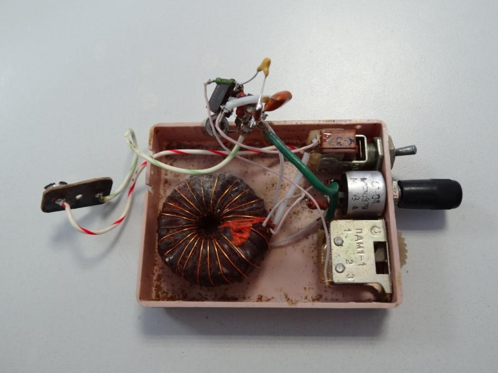
Figure 1. A photo of the device in a disassembled state
The device has a plastic case with two electrodes. On the side are the controls and the power connector. Also included with the fossil was a power supply unit, on the case of which the output voltage of the supply voltage is 5V. Oddly enough, the unit provides all 9.6 volts.
At the exit - a connector for connecting the unit instead of the “crown” with innovative clasps, which deserve special attention, and possibly implementation in other projects (Figure 2).
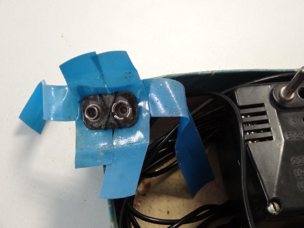
Figure 2. Innovative Power Supply Velcro
The device is equipped with a switch, the sacral meaning of which, apparently, in switching the operating modes of the device, however, the connection location of one of the contacts (archaeologists accidentally broke off the wiring) is not obvious. The switch itself only adds a resistor to the circuit. In general, the instrument control panel is very ergonomic, made according to all the canons of sensationalism. The signal generator itself is made using surface mounting, a tangle of parts lies in the box and even pretends to work (Figure 3).
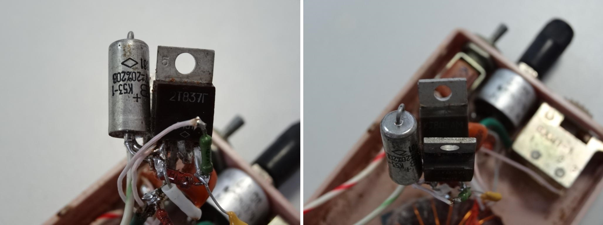
Figure 3. Mounted mounting
Restore the device circuit. It is presented in Figure 4. As you can see, the device is a generator on two transistors. The method of generating a signal would obviously have raised questions for electric eel, but this is not about that now. One of the contacts of the Switch1 switch, as we see, is broken. Presumably, the resistor R3 shunts either the resistor R2 or the entire R2-C2 chain, and maybe something else. Let us try to start the device and see if it works in principle, and if it does, what it gives out to its wonderful electrodes that are held on a powder that once was glue long ago (Figure 5).
The device earned, and even began to issue high-voltage pulses to the electrodes.
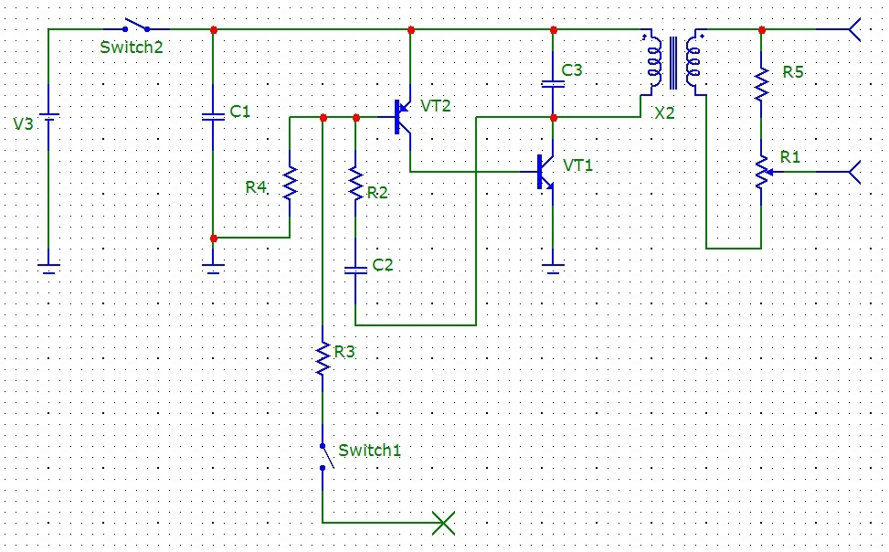
Figure 4. Restored device layout
Determine the ratings of passive elements, types of transistors and restore the device circuit completely.
Face values
Capacitors C1 and C2 have one of the most unstable TKE (denoted as H90, which means TKE = ± 90%). Identify the operating voltage of the capacitors failed.
Capacitor C2 marking 100 nF. The measured value is 112nf.
Capacitor C3 marking 470 nF. The measured value is 449nf.
From time immemorial, the variable resistor R1 has reached us with a worn marking, therefore it remains only to hope for the correctness of the measurements. R1 = 120 kOm
R2 = 150 Om by labeling. Measured value 147 Om.
R3 = 430 kOm by labeling. The measured value is 439 kOm.
R4 = 2 MOm by labeling. The measured value is 2.039 MOm.
R5 = 47 kOm by labeling. The measured value is 47.8 kOm.
Transistors are old Soviet, powerful, with a frequency of 15-20 MHz. Current transfer ratio 15. Voltage Uke = 70 V.
VT1 - KT805AM (npn - type)
VT2 - 2T837G (pnp - type)
The transformer is designed as a torus, more detailed information is currently difficult to obtain. The primary winding of the torus, when measured with a multimeter, gives 750 μH. The secondary winding - 2.2 Gn.
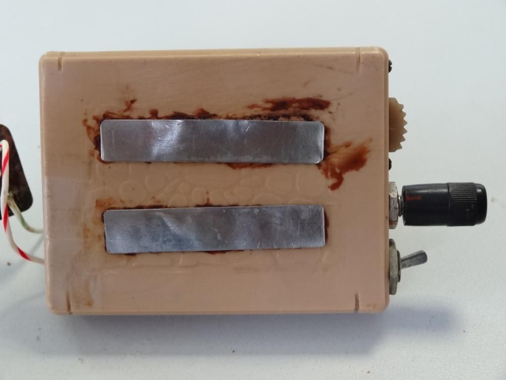
Figure 5. Electrodes
One of the contacts of the Switch1 switch was cut off, so at first glance it was not possible to restore the circuit. After refining all the ratings, it does not seem logical to bypass the 150 Om resistor with a 430 kOm resistor. Consequently, this resistor shunted either the R2-C2 chain or, more likely, the R4 resistor. The full diagram is now shown in Figure 6.

Figure 6. Electrical schematic diagram
Remove the waveform from the output of the device. The signal that he gives to his electrodes. The power at the same time sets the minimum, the load on the electrodes is not. At the output, we see a pulse consisting of several oscillations, the pulse duration of 250 μs. Provided that there is no load on the electrodes, the output signal is about 700 volts. The oscillogram is shown in Figure 7. The first burst has a rather bizarre form, it is shown in detail in the last oscillogram of Figure 7. In general, the signal at idle recalled the signal received from device N (we remove the brand of electroneurostimulation from the report, let us advertise ourselves).
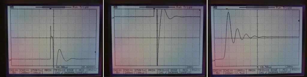
Figure 7. The waveform on the electrodes. Idling
Let's make the same measurements under "loading". The first phalanx of the index finger of the right hand acts as a load. As you can see, the pulse sank, now with a minimum output power of about 50 volts at the output, the waveform has also changed. You can admire the signal itself in figure 8. We will not check the maximum power, it’s pathetic that we’re sorry, they still print a report.
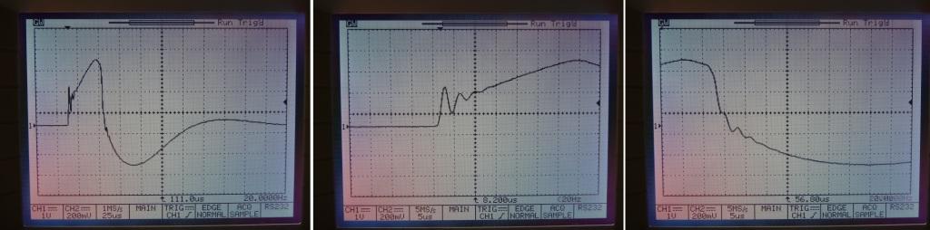
Figure 8. The waveform on the electrodes. Electrodes on the skin
Let's see what happens on the output transistor. Figure 9 shows the oscillogram of the collector voltage of the transistor and the current through it. Based on the oscillograms we can say that the transistor opens for 50 μs. All other oscillations occur due to the oscillating circuit formed by the winding of the transformer and the capacitance C3.
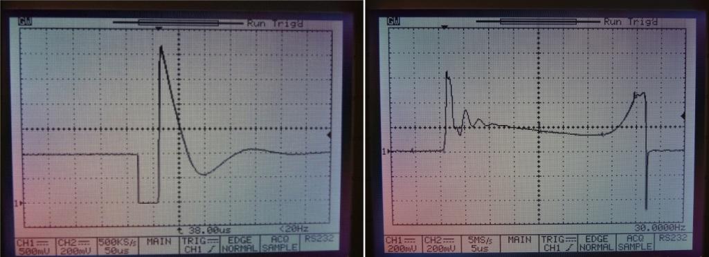
Figure 9. The collector voltage of the output transistor and the current through the transistor
Look at the signal base transistor VT2. The oscillogram from it is shown in Figure 10. As you can see, there saw. At the moment when the voltage at the base of the transistor drops to the unlocking level, the transistor opens, causes the pulse opening of the transistor VT1, and then closes. The voltage on the base with the help of circuit magic rises, after which the capacitor C2 is discharged through the resistor R4. Thus, we receive impulses with the period of 100 ms (frequency of 10 Hz). If you close the switch switch1, the resistor R3 will also participate in the discharge of the capacitor. Then the output pulses will go about 5 times faster (about 50 Hz).
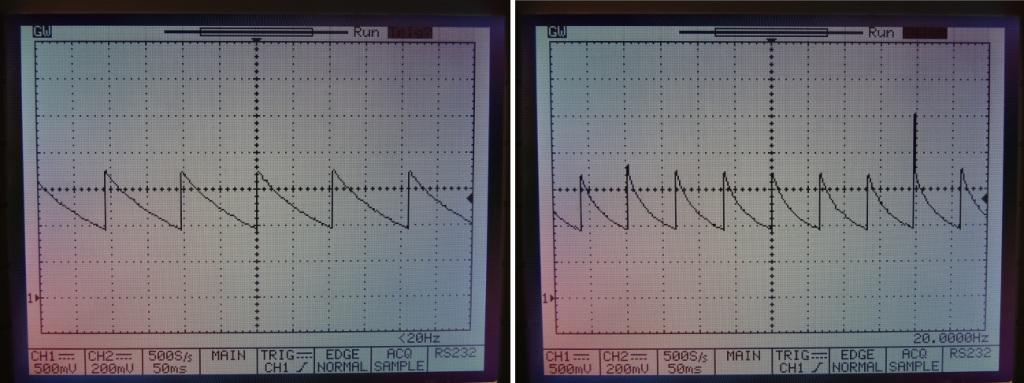
Figure 10. The voltage at the base of the transistor VT2
Well, as a result, the device has been successfully repaired and can continue
Source: https://habr.com/ru/post/446424/
All Articles