Rhino inside the cat - run the firmware in the Kopycat emulator
During the meeting 0x0A DC7831 DEF CON Nizhny Novgorod, on February 16, we presented a report on the basic principles of binary code emulation and our own development - an emulator of Kopycat hardware platforms.
In the article we will describe the launch of the device firmware in the emulator, demonstrate the interaction with the debugger, and perform a small dynamic analysis of the firmware.
Prehistory
A long time ago in a galaxy far far away
A couple of years ago in our laboratory it became necessary to investigate the firmware of the device. The firmware was compressed, unpacked by the bootloader. He did this in a very confused way, shifting data in memory several times. And the firmware itself then actively interacted with the periphery. And all this at the MIPS core.
The existing emulators for objective reasons did not suit us, but I still wanted to run the code. Then they decided to make their own emulator, which will do the minimum and allow unpacking the main firmware. Tried - it turned out. We thought, what if we add peripherals, so that we can also perform the main firmware. It was not very painful - and it also worked out. We thought again and decided to make a full emulator.
The result was an emulation of Kopycat computing systems.

There is a play on words.
- copycat (English, n. [ˈkɒpɪkæt]) - copycat, imitator
- cat (English, n. [ˈkæt]) - a cat, a cat - the favorite animal of one of the creators of the project
- The letter "K" - from the programming language Kotlin
Kopycat
When creating an emulator, quite definite goals were set:
- the ability to quickly create a new periphery, module, processor core;
- the ability to assemble a virtual device from different modules;
- the ability to load into memory of the virtual device any binary data (firmware);
- ability to work with snapshots (snapshots of the system state);
- the ability to interact with the emulator through the built-in debugger;
- nice modern language to develop.
As a result, Kotlin was chosen for implementation, the bus architecture (this is when modules communicate with each other via virtual data buses), JSON as the device description format, and GDB RSP as the protocol for interacting with the debugger.
Development has been going on for a little over two years and is actively continuing. During this time, MIPS, x86, V850ES, ARM, PowerPC processor cores were implemented.
The project is growing, and it's time to introduce it to the general public. A detailed description of the project will be done later, and now we will focus on using Kopycat.
For the most impatient - the promo version of the emulator can be downloaded from the link .
Rhino in the emulator
Earlier, for the conference SMARTRHINO-2018 a test device "Rhino" was created to teach reverse engineering skills. The process of static firmware analysis was described in this article .
Now we will try to add "dynamics" and launch the firmware in the emulator.
We will need:
1) Java 1.8
2) Python and Jep module for using Python inside the emulator. WHL-assembly of the Jep module for Windows can be downloaded here .
For Windows:
1) com0com
2) PuTTY
For Linux:
1) socat
Eclipse, IDA Pro, or radare2 can be used as a GDB client.
How it works?
In order to perform the firmware in the emulator, it is necessary to “assemble” a virtual device, which is an analogue of a real device.
The real device ("rhino") can be shown on the structural diagram:
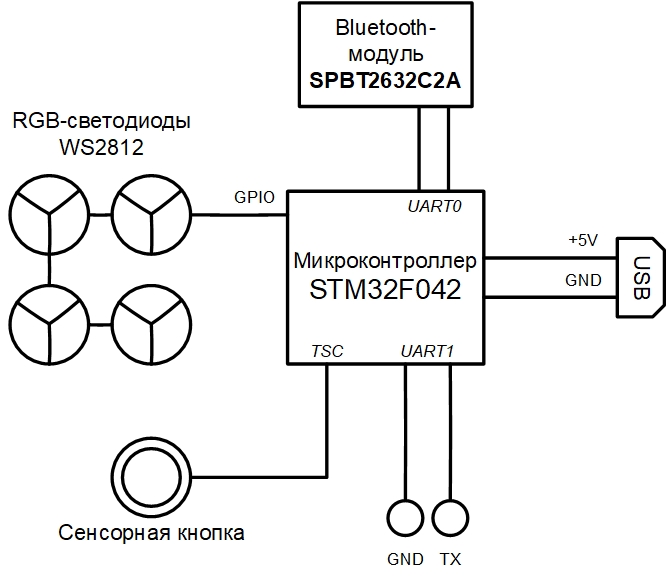
The emulator has a modular structure and the final virtual device can be described in a JSON file.
{ "top": true, // Plugin name should be the same as file name (or full path from library start) "plugin": "rhino", // Directory where plugin places "library": "user", // Plugin parameters (constructor parameters if jar-plugin version) "params": [ { "name": "tty_dbg", "type": "String"}, { "name": "tty_bt", "type": "String"}, { "name": "firmware", "type": "String", "default": "NUL"} ], // Plugin outer ports "ports": [ ], // Plugin internal buses "buses": [ { "name": "mem", "size": "BUS30" }, { "name": "nand", "size": "4" }, { "name": "gpio", "size": "BUS32" } ], // Plugin internal components "modules": [ { "name": "u1_stm32", "plugin": "STM32F042", "library": "mcu", "params": { "firmware:String": "params.firmware" } }, { "name": "usart_debug", "plugin": "UartSerialTerminal", "library": "terminals", "params": { "tty": "params.tty_dbg" } }, { "name": "term_bt", "plugin": "UartSerialTerminal", "library": "terminals", "params": { "tty": "params.tty_bt" } }, { "name": "bluetooth", "plugin": "BT", "library": "mcu" }, { "name": "led_0", "plugin": "LED", "library": "mcu" }, { "name": "led_1", "plugin": "LED", "library": "mcu" }, { "name": "led_2", "plugin": "LED", "library": "mcu" }, { "name": "led_3", "plugin": "LED", "library": "mcu" }, { "name": "led_4", "plugin": "LED", "library": "mcu" }, { "name": "led_5", "plugin": "LED", "library": "mcu" }, { "name": "led_6", "plugin": "LED", "library": "mcu" }, { "name": "led_7", "plugin": "LED", "library": "mcu" }, { "name": "led_8", "plugin": "LED", "library": "mcu" }, { "name": "led_9", "plugin": "LED", "library": "mcu" }, { "name": "led_10", "plugin": "LED", "library": "mcu" }, { "name": "led_11", "plugin": "LED", "library": "mcu" }, { "name": "led_12", "plugin": "LED", "library": "mcu" }, { "name": "led_13", "plugin": "LED", "library": "mcu" }, { "name": "led_14", "plugin": "LED", "library": "mcu" }, { "name": "led_15", "plugin": "LED", "library": "mcu" } ], // Plugin connection between components "connections": [ [ "u1_stm32.ports.usart1_m", "usart_debug.ports.term_s"], [ "u1_stm32.ports.usart1_s", "usart_debug.ports.term_m"], [ "u1_stm32.ports.usart2_m", "bluetooth.ports.usart_m"], [ "u1_stm32.ports.usart2_s", "bluetooth.ports.usart_s"], [ "bluetooth.ports.bt_s", "term_bt.ports.term_m"], [ "bluetooth.ports.bt_m", "term_bt.ports.term_s"], [ "led_0.ports.pin", "u1_stm32.buses.pin_output_a", "0x00"], [ "led_1.ports.pin", "u1_stm32.buses.pin_output_a", "0x01"], [ "led_2.ports.pin", "u1_stm32.buses.pin_output_a", "0x02"], [ "led_3.ports.pin", "u1_stm32.buses.pin_output_a", "0x03"], [ "led_4.ports.pin", "u1_stm32.buses.pin_output_a", "0x04"], [ "led_5.ports.pin", "u1_stm32.buses.pin_output_a", "0x05"], [ "led_6.ports.pin", "u1_stm32.buses.pin_output_a", "0x06"], [ "led_7.ports.pin", "u1_stm32.buses.pin_output_a", "0x07"], [ "led_8.ports.pin", "u1_stm32.buses.pin_output_a", "0x08"], [ "led_9.ports.pin", "u1_stm32.buses.pin_output_a", "0x09"], [ "led_10.ports.pin", "u1_stm32.buses.pin_output_a", "0x0A"], [ "led_11.ports.pin", "u1_stm32.buses.pin_output_a", "0x0B"], [ "led_12.ports.pin", "u1_stm32.buses.pin_output_a", "0x0C"], [ "led_13.ports.pin", "u1_stm32.buses.pin_output_a", "0x0D"], [ "led_14.ports.pin", "u1_stm32.buses.pin_output_a", "0x0E"], [ "led_15.ports.pin", "u1_stm32.buses.pin_output_a", "0x0F"] ] } Note the firmware parameter in the params section — this is the name of the file that can be downloaded to the virtual device as firmware.
A virtual device and its interaction with the main operating system can be represented by the following scheme:
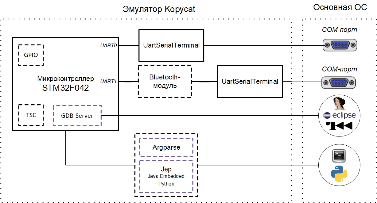
The current test copy of the emulator implies interaction with the COM ports of the main OS (debugging UART and UART for the Bluetooth module). These can be real ports to which devices are connected or virtual COM ports (for this you just need com0com / socat) .
To interact with the emulator from the outside at the moment there are two main ways:
- GDB RSP protocol (respectively, supporting this protocol, tools - Eclipse / IDA / radare2);
- internal emulator command line (Argparse or Python).
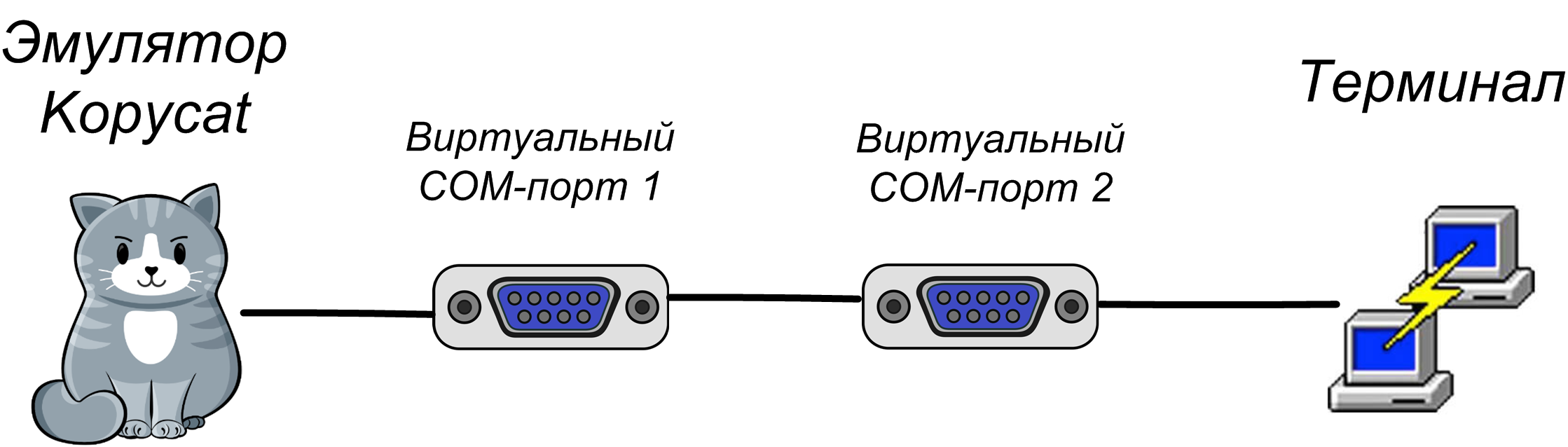
Virtual COM Ports
In order to interact with the UART of a virtual device on a local machine through a terminal, you need to create a pair of connected virtual COM ports. In our case, one port uses the emulator, and the second - the terminal program (PuTTY or screen):
Using com0com
Virtual COM ports are configured by the setup utility from the com0com kit (the console version is C: \ Program Files (x86) \ com0com \ setup.exe, or the GUI version is C: \ Program Files (x86) \ com0com \ setupg.exe ) :
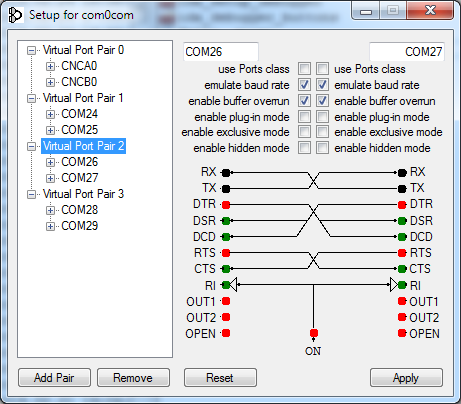
You should check enable buffer overrun for all created virtual ports, otherwise the emulator will expect a response from the COM port.
Using socat
On UNIX systems, virtual COM ports are automatically created by the emulator using the socat utility. To do this, when you start the emulator, specify the socat: prefix in the port name socat:
Internal command line interface (Argparse or Python)
Since Kopycat is a console application, the emulator provides two options for the command line interface for interacting with its objects and variables: Argparse and Python.
Argparse is a CLI built into Kopycat, it is always available and for everyone.
Alternate CLI - Python interpreter. To use it, you need to install the Python module Jep and configure the emulator to work with Python (the Python interpreter installed on the user's main system will be used).
Installing the Jep Python module
Under Linux, Jep can be installed via pip:
pip install jep To install Jep for Windows, you must first install the Windows SDK and the corresponding Microsoft Visual Studio. We have simplified your task a bit and made JEP WHL assemblies for the current versions of Python for Windows, so the module can be installed from a file:
pip install jep-3.8.2-cp27-cp27m-win_amd64.whl To check the installation of Jep, you need to run the command line:
python -c "import jep" In response, a message should be received:
ImportError: Jep is not supported in standalone Python, it must be embedded in Java. In the emulator command file for your system ( kopycat.bat for Windows, kopycat for Linux) add the additional parameter Djava.library.path to the list of DEFAULT_JVM_OPTS parameters — it should contain the path to the installed Jep module.
As a result, Windows should have the following string:
set DEFAULT_JVM_OPTS="-XX:MaxMetaspaceSize=256m" "-XX:+UseParallelGC" "-XX:SurvivorRatio=6" "-XX:-UseGCOverheadLimit" "-Djava.library.path=C:/Python27/Lib/site-packages/jep" Running Kopycat
The emulator is a console JVM application. Run through the operating system command line script (sh / cmd).
The command to run under Windows:
bin\kopycat -g 23946 -n rhino -l user -y library -p firmware=firmware\rhino_pass.bin,tty_dbg=COM26,tty_bt=COM28 The command to run on Linux using the socat utility:
./bin/kopycat -g 23946 -n rhino -l user -y library -p firmware=./firmware/rhino_pass.bin, tty_dbg=socat:./COM26,tty_bt=socat:./COM28 -g 23646- TCP port that will be opened for access to the GDB server;-n rhino- the name of the main module of the system (device assembly);-l user- library name to search for the main module;-y library- the path to search for modules included in the device;firmware\rhino_pass.bin- path to the firmware file;- COM26 and COM28 are virtual COM ports.
As a result, the Python > (or Argparse > ) prompt will be displayed:
18:07:59 INFO [eFactoryBuilder.create ]: Module top successfully created as top 18:07:59 INFO [ Module.initializeAndRes]: Setup core to top.u1_stm32.cortexm0.arm for top 18:07:59 INFO [ Module.initializeAndRes]: Setup debugger to top.u1_stm32.dbg for top 18:07:59 WARN [ Module.initializeAndRes]: Tracer wasn't found in top... 18:07:59 INFO [ Module.initializeAndRes]: Initializing ports and buses... 18:07:59 WARN [ Module.initializePortsA]: ATTENTION: Some ports has warning use printModulesPortsWarnings to see it... 18:07:59 FINE [ ARMv6CPU.reset ]: Set entry point address to 08006A75 18:07:59 INFO [ Module.initializeAndRes]: Module top is successfully initialized and reset as a top cell! 18:07:59 INFO [ Kopycat.open ]: Starting virtualization of board top[rhino] with arm[ARMv6Core] 18:07:59 INFO [ GDBServer.debuggerModule ]: Set new debugger module top.u1_stm32.dbg for GDB_SERVER(port=23946,alive=true) Python > Interaction with IDA Pro
As a source file for analysis in IDA, to simplify testing, we use the “Rhino” firmware in the form of an ELF file (meta information is stored there).
You can also use the main firmware without metainformation.
After launching Kopycat in IDA Pro, in the Debugger menu, go to the " Switch debugger ... " item and select " Remote GDB debugger ". Next, configure the connection: menu Debugger - Process options ...
Set values:
- Application - any value
- Hostname: 127.0.0.1 (or the IP address of the remote machine where Kopycat is running)
- Port: 23946

Now the debug start button is available (F9 key):

Click it - it connects to the debugger module in the emulator. IDA goes into debug mode, additional windows become available: information about registers, about the stack.
Now we can use all standard debugger features:
- step-by-step execution of instructions ( Step into and Step over - keys F7 and F8, respectively);
- start and pause;
- creating breakpoints both on code and on data (F2 key).
Connecting to the debugger does not mean running the firmware code. The current position for execution must be the address 0x08006A74 - the beginning of the Reset_Handler function. If you scroll the listing below, you can see the main function call. You can position the cursor on this line (address 0x08006ABE ) and perform the Run until cursor operation (F4 key).
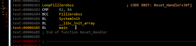
Then you can press F7 to enter the main function.
If you run the Continue process command (F9 key), the "Please wait" window will appear with a single Suspend button:
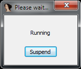
When you click Suspend, the execution of the firmware code is suspended and can be continued from the same address in the code where it was interrupted.
If you continue the execution of the code, then in the terminals connected to the virtual COM ports, you can see the following lines:
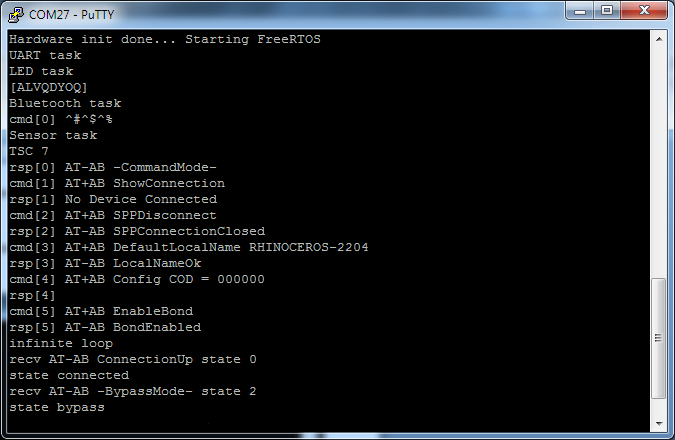
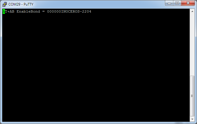
The presence of the line "state bypass" indicates that the virtual Bluetooth module has switched to the mode of receiving data from the user's COM port.
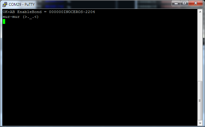
Now, in the Bluetooth terminal (in the figure - COM29), you can enter commands in accordance with the "Rhino" protocol. For example, the string "mur-mur" will return to the "MEOW" command in the Bluetooth terminal:
Emulate me not completely
When building an emulator, you can choose the level of detail / emulation of a device. For example, the Bluetooth module can be emulated in different ways:
- fully device emulated with a full set of commands;
- AT commands are emulated, and the data stream is received from the main system COM port;
- virtual device provides full redirection of data to the real device;
- in the form of a simple stub, which always returns "OK".
In the current version of the emulator, the second approach is used - the virtual Bluetooth module performs configuration, after which it switches to the "proxying" mode of data from the COM port of the main system to the UART port of the emulator.

Consider the possibility of simple code instrumentation if some part of the periphery is not implemented. For example, if a timer is not created that is responsible for controlling the data transfer in DMA (the check is performed in the ws2812b_wait function located at 0x08006840 ), then the firmware will always wait for the busy flag reset located at 0x200004C4 , which shows the DMA data line occupancy:

We can bypass such a situation by "manually" resetting the busy flag immediately after its installation. In IDA Pro, you can create a Python function and call it in a breakpoint, while putting the breakpoint itself in the code after writing the value 1 to the busy flag.
Breakpoint handler
First, create a Python function in IDA. File menu - Script command ...
Add a new snippet in the list on the left, give it a name (for example, BPT ),
In the text box on the right, enter the function code:
def skip_dma(): print "Skipping wait ws2812..." value = Byte(0x200004C4) if value == 1: PatchDbgByte(0x200004C4, 0) return False 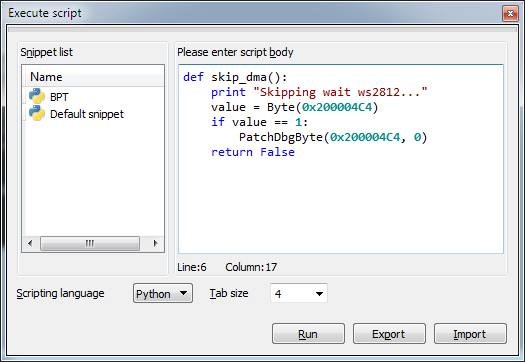
After that, click Run and close the script window.
Now let's move to the code at 0x0800688A , set the breakpoint (F2 key), edit it ( Edit breakpoint context menu ... ), let's not forget to set the script type - Python:


If the current value of the busy flag is 1, then the skip_dma function should be executed in the script line:
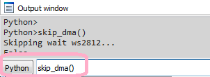
If you run the firmware for execution, then the triggering of the breakpoint-handler code can be seen in IDA in the Output window along the line Skipping wait ws2812... Now the firmware will not expect to reset the busy flag.
Interaction with the emulator
Emulation for the sake of emulation is unlikely to cause delight and joy. It is much more interesting if the emulator helps the researcher to see the data in memory or to establish the interaction of streams.
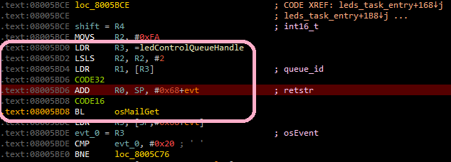
Let us show how to establish the interaction of RTOS tasks in dynamics. You should first suspend code execution if it is running. If you go to the bluetooth_task_entry function in the processing branch of the "LED" command (address 0x080057B8 ), you can see what is created first, and then some message is sent to the ledControlQueueHandle system queue.

You should set a breakpoint to access the ledControlQueueHandle variable located at 0x20000624 and continue with the code:

As a result, it will first stop at address 0x080057CA before calling the function osMailAlloc , then at address 0x08005806 before calling the function osMailPut , then after a while at address 0x08005BD4 (before calling the function osMailGet ), which belongs to the function leds_task_entry (LED-task), that is, There was a switch of tasks, and now the control has received a LED task.
In such a simple way, it is possible to establish how RTOS tasks interact with each other.
Of course, in reality, the interaction of tasks can be more complicated, but using the emulator to track this interaction becomes less time consuming.
Here you can watch a small video of the emulator launch and interaction with IDA Pro.
Run with Radare2
You can not ignore such a universal tool like Radare2.
To connect to the emulator using r2, the command will look like this:
radare2 -A -a arm -b 16 -d gdb://localhost:23946 rhino_fw42k6.elf Startup ( dc ) and suspension of execution (Ctrl + C) are now available.
Unfortunately, at the moment in r2 there are problems when working with a hard-core gdb server and memory markup, because of this, breakpoints and Stepes do not work ( ds command). We hope this will be fixed soon.
Run with Eclipse
One of the uses of the emulator is to debug the firmware of the device being developed. For clarity, we will also use the firmware "Rhino". Download the firmware sources from here .
As an IDE, we will use Eclipse from the System Workbench for STM32 suite.
In order for the emulator to load the firmware directly compiled in Eclipse, you need to add the parameter firmware=null to the command to start the emulator:
bin\kopycat -g 23946 -n rhino -l user -y library -p firmware=null,tty_dbg=COM26,tty_bt=COM28 Configuring debug configuration
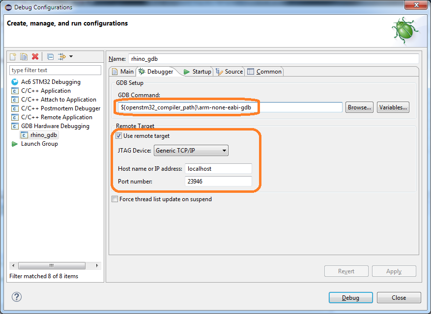
In Eclipse, select the menu Run - Debug Configurations ... In the window that opens, in the GDB Hardware Debugging section, you need to add a new configuration, and then on the Main tab specify the current project and application for debugging:

On the "Debugger" tab, you need to specify the GDB command:${openstm32_compiler_path}\arm-none-eabi-gdb
And also enter the parameters for connecting to the GDB server (host and port):
On the "Startup" tab, you must specify the following parameters:
- Enable the Load image checkbox (to load the assembled image of the firmware into the emulator);
- Enable the tick Load symbols ;
- add a start command:
set $pc = *0x08000004(set the PC register value from the memory at0x08000004- the0x08000004address is stored there).
Note that if you do not want to load the firmware file from Eclipse, then you do not need to specify the parameters Load image and Run commands .

After clicking Debug you can work in debugger mode:
- step-by-step code execution

- interaction with breakpoints

Note Eclipse has, hmm ... some features ... and you have to live with them. Here, for example, if the message "No source available for" 0x0 "appears when starting the debugger, then execute the Step command (F5)

Instead of conclusion
Native code emulation is very interesting. For the device developer, it is possible to debug the firmware without a real device. For the researcher - the ability to conduct dynamic code analysis, which is not always possible even with the device.
We want to provide specialists with a tool that would be convenient, fairly simple and did not take much time and effort to set up and launch.
Write in the comments about your experience using hardware emulators. We invite you to the discussion and will be happy to answer questions.
')
Source: https://habr.com/ru/post/445798/
All Articles