We develop pedal firmware for learning to play the balalaika
I love video tutorials. For some reason, I personally perceive the information from the text very, very badly. And there are things in which there is not much information on paper. Take, for example, the balalaika lessons: there are wonderful debates on YouTube, how to play this or that melody (who cares, we search by name "Sergey Vorontsov"), but it is difficult to repeat and memorize the sequence from streaming video. It is necessary either to write down on paper (judging by the comments under the lessons, some do so), or to re-buy additional materials (but I am not greedy, but homely).

In general, in my balalaic case, and for many others, one should go like this: looked at the fragment, paused, repeated several times after the author, continued viewing. If something is not clear - I rewind back, looked more closely. But how does it all wind up if your hands are busy? Moreover, in my case they are busy, albeit not with a huge button accordion, but still some kind of balalaika. So, you have to work with your feet.
Many, many years ago, when all progressive humanity used PS / 2 keyboards, they brought us a dozen USB keyboards for the project. Of course, we connected them to one machine, clicked Ctrl on one of them, Alt on the second, and Del on the third. The effect has been achieved. Since then, I know that USB keyboards work completely parallel, so to help the main one, you can connect another one, which will send some codes instead.
')
So the idea was born to make a pedal that pretends to be a keyboard and sends the player control codes. As a player, I initially chose VLC Player, as it has well-documented control buttons, but later it turned out that the codes I chose have the exact same purpose when watching videos on YouTube in full-screen mode. This is good, as with multiple online views for ad impressions, it seems that the author has something to do. Looking in the downloaded form would not be so ethical.
So, we start designing the device.
At first I wanted to make several pedals, each for its own function. Initially, I counted 3-4 functions of these functions: on, off, wind there, wind back. But then I figured out how much plastic it would take, plus - how I would sort out the pedals, and I was sad. Therefore, it was decided to radically revise all the logic. What functions are generally needed? Start-stop, but it often hangs on the same key, usually on the space. And roll back. The VLC Player is “Shift + Left”. In YouTube, as it turned out, too. And, if you think so - more functions and not necessary.
Perfectly! Let's make a short pedal pressing the “start-stop” function, and a long one - with the “rewind back” function.
In the future, you can extend the functionality. You can train the pedal recognition Morsechians. My wife, having learned about the idea, suggested coding control pulses using elements of Irish dancing ... In general, you can extend the functionality as you please. But one thing is clear: one pedal is enough. Well, now we will do the recognition of long and short clicks.
For those who go home in slippers, there is a very simple solution (I found it on the Thingiverse website). We take a button with a diameter of more than a centimeter, we twist it into any box-shaped object, we get a pedal. The trouble is that I do not like sneakers, so this option does not suit me personally. I need a larger surface area so that the foot does not hurt.
Pedals in huge quantities are sold on Ali Express, you should look for the word Foot Switch. The prices there start from 30 rubles, but at this price the cost of delivery may be about four hundred rubles. Searching, I found out that it is quite possible to find such a pedal, for which the sum “price plus delivery” will be 150 rubles. But it will take an average of a couple of months to wait (I recently waited here for an SD card for all three months).
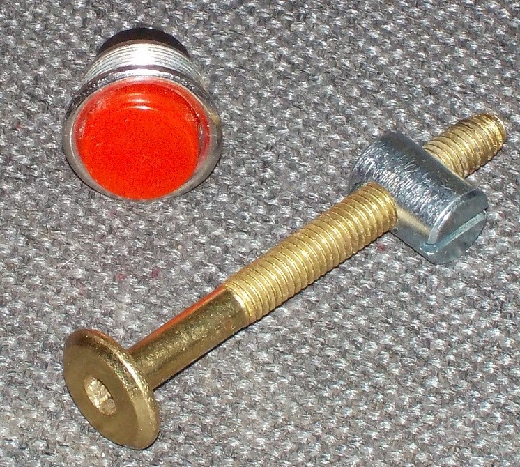
So I went the faster way: I made a pedal on a 3D printer. Personal experience (and all options with Thingiverse) shows that the axis must be metal, otherwise everything will quickly break. I took the furniture bolt M6x60 that I had with the nut attached to it, as well as the button (PSW-13) in the neighboring Radio Parts and painted them around with plastic as I could. Here are the source materials:
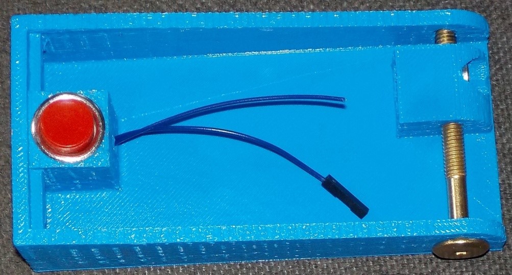
Here they are inserted in the bottom half. As you can see, the main feature of the design is walls, at least four millimeters thick. With such parameters, even the gentle proto-type becomes quite durable. The button is installed without a nut, since any void under it will lead to a plastic break, and it holds up pretty well and so.
Here is an almost assembled version:
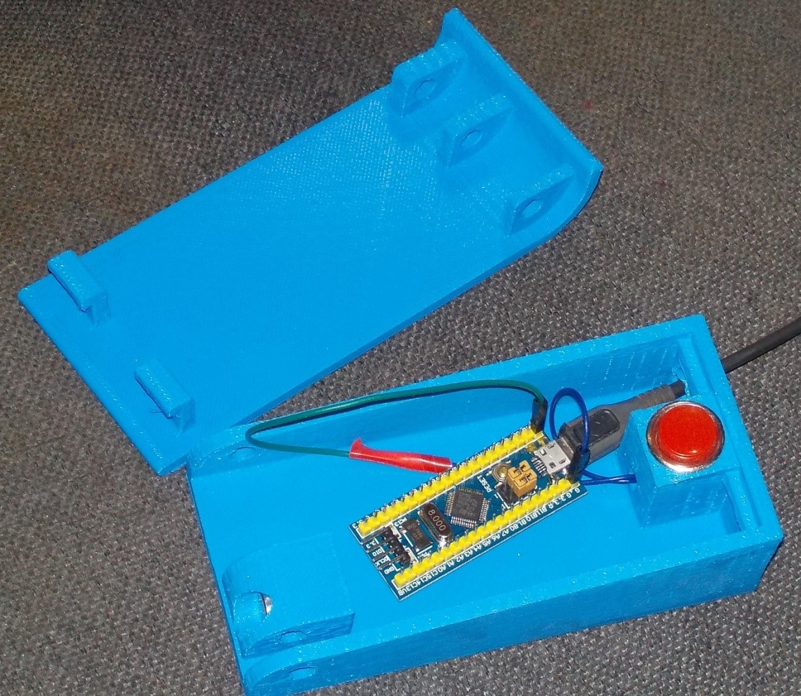
And here is the pedal assembly:
Basically, I will attach the STL files, but the solution was not perfect. However, anyone will be able to repeat it (if they find an M6x60 bolt with the appropriate nut and a PSW-13 button). For the first time, that's enough, and then - you can stamped mechanics and order with ALI.
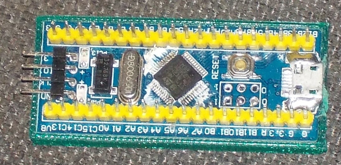
Though lately I have been actively promoting PSoC, in the pedals to use it is unheard of waste. The best solution is to consider a mock-up board based on the STM32F103C8T6, which can now be ordered on ALI Express for about 120 rubles (including shipping).
You can, of course, speculate that there are cheaper AVR-based motherboards, but the price difference is not significant there, and the development time, due to debugging via JTAG, is much less for STM32. An hour of time (even if it is home) - it is also worth something. So, according to the total criterion "price of the device + price of labor costs" STM32F103 is the best option for this task. Especially since I have about a dozen of such prototypes in store for just such a case, so the waiting time for delivery is now zero for me.
I rummaged in the network in search of ready-made USB-keyboards based on this crystal. On Habré found an article on how to make a USB mouse. But I need a keyboard. On the topic of keyboards, I found many clever tips on the forums (but I wanted something finished) and a couple of some ready-made, but complex projects on GitHub (and I wanted something understandable). But he who seeks will always find. Here is a wonderful article that has everything you need (even if it’s in the code, I’m not afraid of this non-Russian word, potential DeadLock, but I will write my own code). The main thing is that it clearly describes all the steps, like from a ready-made “fish” made in Cube MX, to get exactly the USB keyboard. The only thing that the author did not, did not publish key codes. Add them here:
The spoon of tar is that in the modern version of the Cube MX, the names of files, functions, and even constants are slightly different from those specified in that article, but by analogy everything is fast. I could write a new version of the text, but where is the guarantee that the developers will not change everything again? They love to do it. In general, you can see analogues in my example.
So. I created a basic project in Cube MX, made all the changes recommended by the article mentioned above. What's next? Next, add a description of the port button. I chose PB12 (purely because the corresponding contact is located on the corner of the layout). Since I always work with iron through the mcucpp library of Konstantin Chizhov, we remove the “-C99” macro in the project properties, rename main.c to main.cpp , and then add the declaration to:
In the main () function, we add port initialization (switching on port clocking, setting the direction of the leg, turning on the suspender):
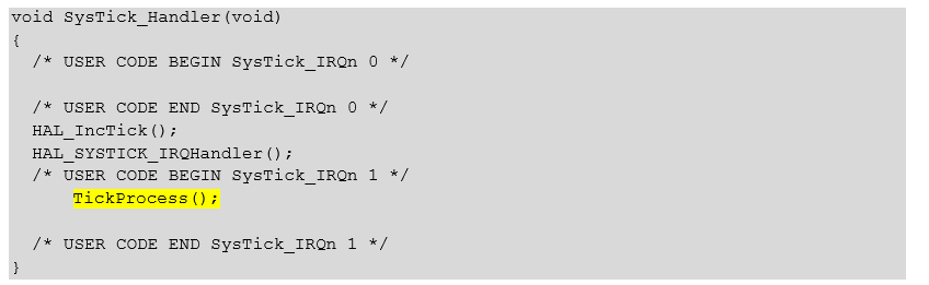
Actually, with all the initialization. I decided to build the main body in the image of the Verilog process. I do not know why, just wanted. A process is usually triggered by a clock pulse. I decided that system tics are perfectly taken as clock ticks. Therefore, the standard function of the system tick handler in the stm32f1xx_it.c file is added as follows:
I put the TickProcess () function in main. cpp . First, consider it in its entirety, then - in parts.
The first task that is implemented in this handler is simple. Every 20 milliseconds we send a report containing information about the pressed buttons (if there are no buttons, we still send, just with zeros). Since the function is called every millisecond, the report should be sent to one of its twenty calls. For this there is a variable at the beginning of the function:
and the code at the end (we send the data, then we overwrite the buffer in order to start sending zeros from the next session):
The second task is more difficult. She tracks the nature of pressing the pedal and fills the report for later sending. Why did I say that ideology is like Verilog? Because I always catch differences in that language: I have a variable in which the current state of the button is put:
and there is a variable in which its previous state is stored (as we remember, the previous state is the button state during the previous processing of the 1 ms timer interrupt):
The pressed button gives the value false , the pressed button - true . Thus, you can always conclude about the dynamic state of the button:
We introduce two constants. One sets the time for a short press. If the press lasted less than 700 ms, then it is short. The second sets the time when auto-repeat is enabled. If you simply start sending the key code after seven hundred milliseconds, the player will start to shake too sharply. This is revealed empirically. Therefore, the logic of operation is as follows: after 700 ms, a single “Shift + Left” code is sent, after which the user is given the opportunity to release the pedal. If the pedal is continued to be held, then from the second second, the constant sending of this code begins until the pedal is released.
The time during which the button is pressed is stored in a variable:
If the button has just been pressed, zero this variable, starting to measure the new time period:
If the button has just been released, then we check the time how long it was pressed. If quite a bit (now “less than 100 ms” is inscribed), it is a bounce. This does not count. Ignore this click. If it is longer than the duration of a short press, we also do nothing; long presses are processed below. If, within a short press, we generate a report with a space in the buffer (which will be sent when the time comes for this):
If the button has been held for a long time, then we send “Shift + Left” in two cases:
That's all. More than this code is no different from the "fish" that we made the Cube MX. Collecting, stitching ... No, it's impossible without errors (here they are all captured, but I initially couldn't do without them), we detect them in 10 minutes through JTAG debugging (hello to AVR), we sew, rejoice ...
In general, such things are useful without a balalaika (or other viewing of video lessons). In particular, I like to read the news, lying in bed, with a laptop on my stomach. To scroll the text, you have to keep your right arm bent all the time, and this leads to pain in the elbow. Therefore, I have long dreamed of a big red button that could scroll pages without bending a hand. Actually, it can be made from the same components as the pedal, replacing the furniture bolt with a small amount of hot melt glue. Total: button PSW13, layout STM32F103C8T6, plastic for 3D printer, hot melt glue. Well, in the “firmware” I replaced the codes with “PgDn” by a short press and “Up” by a long one.
You can use your legs to control the display of video lessons when your hands are busy. To do this, just one pedal, imitating the operation of the USB-keyboard. One pedal can send multiple key codes by selecting them based on various types of keystrokes. The article discusses a pedal that disassembles two types (short and long press).
Mechanics can be found on Ali Express with the word Foot Switch or can be printed on a 3D printer. As electronics, a STM32F103C8T6 prototype board can be used. “Firmware” is done in less than an hour on the basis of “fish” created by Cube MX from the manufacturer of the STM32 controllers. The additional code takes up several screens of text (for 2K resolution, one screen).
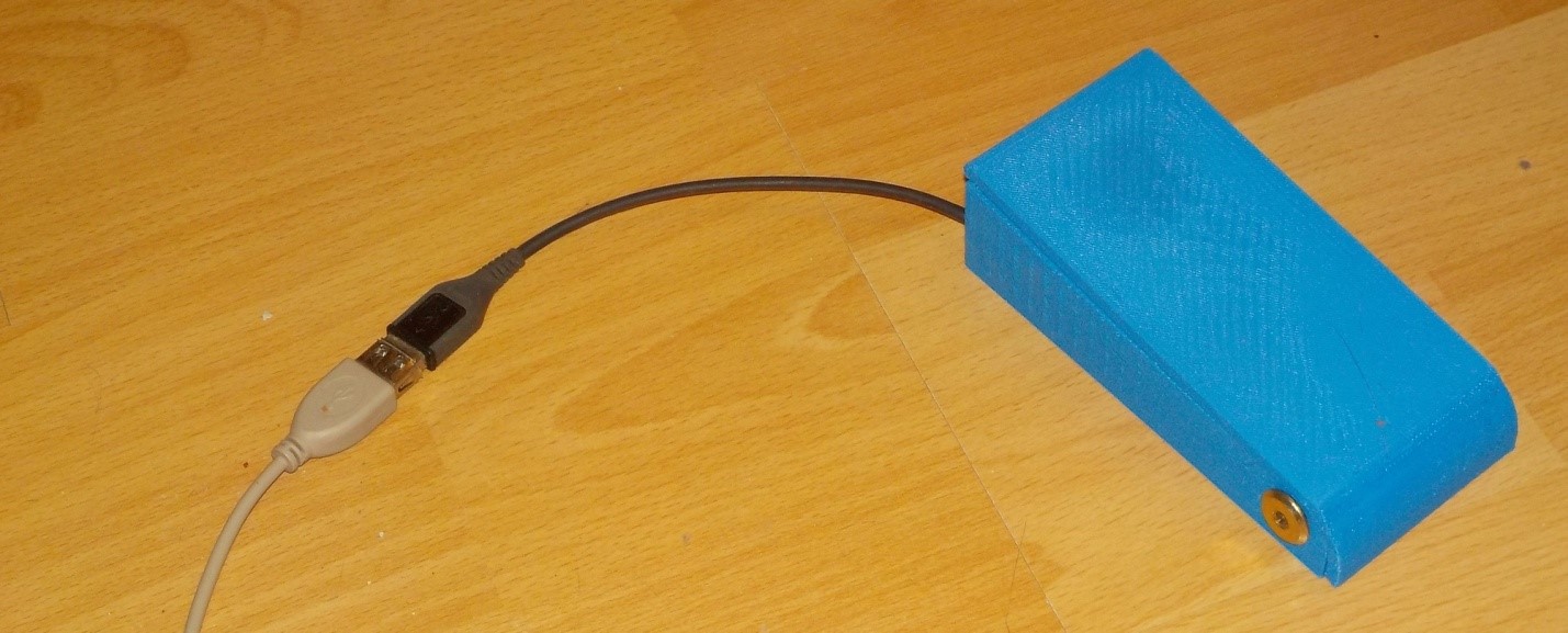
In general, the entire device (mechanics + “firmware”) was completely designed in one evening, plus it took about four hours to print the mechanics on a 3D printer.
Ready STL files for pedal printing can be downloaded here (the Top element should preferably be lowered by 0.4 mm to avoid a large number of supports: the surface turned out to be slightly rounded, lowering the model, we will make the printed part flat).
STL files of the “big red button” can be downloaded here .
The finished project source files and the HEX firmware file can be downloaded here .
Date of publication of this article was not chosen randomly. The council decided that it was better to publish an article about such things on a serious website that day. But in fact, if you watch videos found by the phrases “Alexey Arkhipovsky”, “Dmitry Kalinin”, “Cranberry Show”, “Alexey Kodenko”, then it becomes clear that the academic balalaika is like an assembler. Both there and there absolute simplicity and mad expressive power are combined. And according to the phrase "Sergey Vorontsov" you can understand how to learn how to use this tool.
In general, in my balalaic case, and for many others, one should go like this: looked at the fragment, paused, repeated several times after the author, continued viewing. If something is not clear - I rewind back, looked more closely. But how does it all wind up if your hands are busy? Moreover, in my case they are busy, albeit not with a huge button accordion, but still some kind of balalaika. So, you have to work with your feet.
Many, many years ago, when all progressive humanity used PS / 2 keyboards, they brought us a dozen USB keyboards for the project. Of course, we connected them to one machine, clicked Ctrl on one of them, Alt on the second, and Del on the third. The effect has been achieved. Since then, I know that USB keyboards work completely parallel, so to help the main one, you can connect another one, which will send some codes instead.
')
So the idea was born to make a pedal that pretends to be a keyboard and sends the player control codes. As a player, I initially chose VLC Player, as it has well-documented control buttons, but later it turned out that the codes I chose have the exact same purpose when watching videos on YouTube in full-screen mode. This is good, as with multiple online views for ad impressions, it seems that the author has something to do. Looking in the downloaded form would not be so ethical.
So, we start designing the device.
Work logic
At first I wanted to make several pedals, each for its own function. Initially, I counted 3-4 functions of these functions: on, off, wind there, wind back. But then I figured out how much plastic it would take, plus - how I would sort out the pedals, and I was sad. Therefore, it was decided to radically revise all the logic. What functions are generally needed? Start-stop, but it often hangs on the same key, usually on the space. And roll back. The VLC Player is “Shift + Left”. In YouTube, as it turned out, too. And, if you think so - more functions and not necessary.
Perfectly! Let's make a short pedal pressing the “start-stop” function, and a long one - with the “rewind back” function.
In the future, you can extend the functionality. You can train the pedal recognition Morsechians. My wife, having learned about the idea, suggested coding control pulses using elements of Irish dancing ... In general, you can extend the functionality as you please. But one thing is clear: one pedal is enough. Well, now we will do the recognition of long and short clicks.
Mechanics
For those who go home in slippers, there is a very simple solution (I found it on the Thingiverse website). We take a button with a diameter of more than a centimeter, we twist it into any box-shaped object, we get a pedal. The trouble is that I do not like sneakers, so this option does not suit me personally. I need a larger surface area so that the foot does not hurt.
Pedals in huge quantities are sold on Ali Express, you should look for the word Foot Switch. The prices there start from 30 rubles, but at this price the cost of delivery may be about four hundred rubles. Searching, I found out that it is quite possible to find such a pedal, for which the sum “price plus delivery” will be 150 rubles. But it will take an average of a couple of months to wait (I recently waited here for an SD card for all three months).
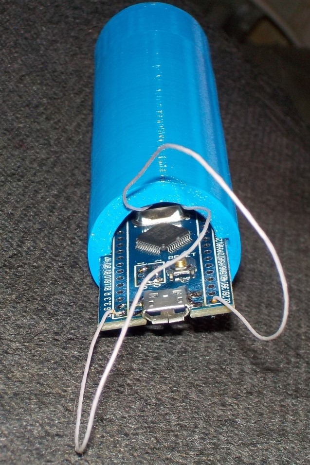
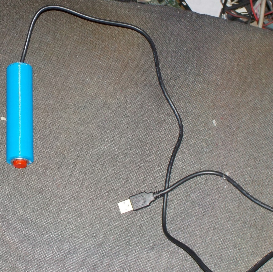
So I went the faster way: I made a pedal on a 3D printer. Personal experience (and all options with Thingiverse) shows that the axis must be metal, otherwise everything will quickly break. I took the furniture bolt M6x60 that I had with the nut attached to it, as well as the button (PSW-13) in the neighboring Radio Parts and painted them around with plastic as I could. Here are the source materials:
Here they are inserted in the bottom half. As you can see, the main feature of the design is walls, at least four millimeters thick. With such parameters, even the gentle proto-type becomes quite durable. The button is installed without a nut, since any void under it will lead to a plastic break, and it holds up pretty well and so.
Here is an almost assembled version:
And here is the pedal assembly:
Basically, I will attach the STL files, but the solution was not perfect. However, anyone will be able to repeat it (if they find an M6x60 bolt with the appropriate nut and a PSW-13 button). For the first time, that's enough, and then - you can stamped mechanics and order with ALI.
USB device
Though lately I have been actively promoting PSoC, in the pedals to use it is unheard of waste. The best solution is to consider a mock-up board based on the STM32F103C8T6, which can now be ordered on ALI Express for about 120 rubles (including shipping).
You can, of course, speculate that there are cheaper AVR-based motherboards, but the price difference is not significant there, and the development time, due to debugging via JTAG, is much less for STM32. An hour of time (even if it is home) - it is also worth something. So, according to the total criterion "price of the device + price of labor costs" STM32F103 is the best option for this task. Especially since I have about a dozen of such prototypes in store for just such a case, so the waiting time for delivery is now zero for me.
I rummaged in the network in search of ready-made USB-keyboards based on this crystal. On Habré found an article on how to make a USB mouse. But I need a keyboard. On the topic of keyboards, I found many clever tips on the forums (but I wanted something finished) and a couple of some ready-made, but complex projects on GitHub (and I wanted something understandable). But he who seeks will always find. Here is a wonderful article that has everything you need (even if it’s in the code, I’m not afraid of this non-Russian word, potential DeadLock, but I will write my own code). The main thing is that it clearly describes all the steps, like from a ready-made “fish” made in Cube MX, to get exactly the USB keyboard. The only thing that the author did not, did not publish key codes. Add them here:
The spoon of tar is that in the modern version of the Cube MX, the names of files, functions, and even constants are slightly different from those specified in that article, but by analogy everything is fast. I could write a new version of the text, but where is the guarantee that the developers will not change everything again? They love to do it. In general, you can see analogues in my example.
So. I created a basic project in Cube MX, made all the changes recommended by the article mentioned above. What's next? Next, add a description of the port button. I chose PB12 (purely because the corresponding contact is located on the corner of the layout). Since I always work with iron through the mcucpp library of Konstantin Chizhov, we remove the “-C99” macro in the project properties, rename main.c to main.cpp , and then add the declaration to:
typedef Mcucpp::IO::Pb12 pedal1; In the main () function, we add port initialization (switching on port clocking, setting the direction of the leg, turning on the suspender):
pedal1::ConfigPort::Enable(); pedal1::SetDirRead(); pedal1::SetPullUp (pedal1::Port::PullUp); Actually, with all the initialization. I decided to build the main body in the image of the Verilog process. I do not know why, just wanted. A process is usually triggered by a clock pulse. I decided that system tics are perfectly taken as clock ticks. Therefore, the standard function of the system tick handler in the stm32f1xx_it.c file is added as follows:
Same text:
void SysTick_Handler(void) { /* USER CODE BEGIN SysTick_IRQn 0 */ /* USER CODE END SysTick_IRQn 0 */ HAL_IncTick(); HAL_SYSTICK_IRQHandler(); /* USER CODE BEGIN SysTick_IRQn 1 */ TickProcess(); /* USER CODE END SysTick_IRQn 1 */ } I put the TickProcess () function in main. cpp . First, consider it in its entirety, then - in parts.
Here is the full feature:
uint8_t report [8] = {0,0,0,0,0,0,0,0}; uint32_t* pReport = (uint32_t*)report; extern "C" void TickProcess() { // 20!!! static const int shortTime = 700; // static const int longTime = 2000; // static int localTick = 0; static int tickDuringButton = 0; static bool bButtonStatePrev; bool bButtonState = pedal1::IsSet(); // if ((!bButtonState) && bButtonStatePrev) { tickDuringButton = 0; } // if (bButtonState && (!bButtonStatePrev)) { // // , 50 () if ((tickDuringButton >100)&&(tickDuringButton < shortTime)) { // report [2] = 0x2C; } } // if ((!bButtonState) && (!bButtonStatePrev)) { if ((tickDuringButton == shortTime)||(tickDuringButton > longTime)) { // Shift+ report [0] = 2; // Shift report [2] = 0x50; // } } // bButtonStatePrev = bButtonState; tickDuringButton += 1; if (localTick++ % 20 == 0) { USBD_HID_SendReport (&hUsbDeviceFS,report,sizeof(report)); pReport [0] = 0; pReport [1] = 0; } } The first task that is implemented in this handler is simple. Every 20 milliseconds we send a report containing information about the pressed buttons (if there are no buttons, we still send, just with zeros). Since the function is called every millisecond, the report should be sent to one of its twenty calls. For this there is a variable at the beginning of the function:
static int localTick = 0; and the code at the end (we send the data, then we overwrite the buffer in order to start sending zeros from the next session):
if (localTick++ % 20 == 0) { USBD_HID_SendReport (&hUsbDeviceFS,report,sizeof(report)); pReport [0] = 0; pReport [1] = 0; } The second task is more difficult. She tracks the nature of pressing the pedal and fills the report for later sending. Why did I say that ideology is like Verilog? Because I always catch differences in that language: I have a variable in which the current state of the button is put:
bool bButtonState = pedal1::IsSet(); and there is a variable in which its previous state is stored (as we remember, the previous state is the button state during the previous processing of the 1 ms timer interrupt):
static bool bButtonStatePrev; The pressed button gives the value false , the pressed button - true . Thus, you can always conclude about the dynamic state of the button:
| bButtonState | bButtonStatePrev | condition |
|---|---|---|
| true | true | Long released |
| true | false | Released at the previous measure |
| false | true | Pressed on the previous measure |
| false | false | Long pressed |
We introduce two constants. One sets the time for a short press. If the press lasted less than 700 ms, then it is short. The second sets the time when auto-repeat is enabled. If you simply start sending the key code after seven hundred milliseconds, the player will start to shake too sharply. This is revealed empirically. Therefore, the logic of operation is as follows: after 700 ms, a single “Shift + Left” code is sent, after which the user is given the opportunity to release the pedal. If the pedal is continued to be held, then from the second second, the constant sending of this code begins until the pedal is released.
const int shortTime = 700; // const int longTime = 2000; // The time during which the button is pressed is stored in a variable:
static int tickDuringButton = 0; If the button has just been pressed, zero this variable, starting to measure the new time period:
// if ((!bButtonState) && bButtonStatePrev) { tickDuringButton = 0; } If the button has just been released, then we check the time how long it was pressed. If quite a bit (now “less than 100 ms” is inscribed), it is a bounce. This does not count. Ignore this click. If it is longer than the duration of a short press, we also do nothing; long presses are processed below. If, within a short press, we generate a report with a space in the buffer (which will be sent when the time comes for this):
// if (bButtonState && (!bButtonStatePrev)) { // // , 100 () if ((tickDuringButton >100)&&(tickDuringButton < shortTime)) { // report [2] = 0x2C; } } If the button has been held for a long time, then we send “Shift + Left” in two cases:
- button hold exactly 700 ms (single package);
- hold the button for more than 2 seconds (sending in each subsequent report until the button is released).
// if ((!bButtonState) && (!bButtonStatePrev)) { if ((tickDuringButton == shortTime)||(tickDuringButton > longTime)) { // Shift+ report [0] = 2; // Shift report [2] = 0x50; // } } That's all. More than this code is no different from the "fish" that we made the Cube MX. Collecting, stitching ... No, it's impossible without errors (here they are all captured, but I initially couldn't do without them), we detect them in 10 minutes through JTAG debugging (hello to AVR), we sew, rejoice ...
Alternative design
In general, such things are useful without a balalaika (or other viewing of video lessons). In particular, I like to read the news, lying in bed, with a laptop on my stomach. To scroll the text, you have to keep your right arm bent all the time, and this leads to pain in the elbow. Therefore, I have long dreamed of a big red button that could scroll pages without bending a hand. Actually, it can be made from the same components as the pedal, replacing the furniture bolt with a small amount of hot melt glue. Total: button PSW13, layout STM32F103C8T6, plastic for 3D printer, hot melt glue. Well, in the “firmware” I replaced the codes with “PgDn” by a short press and “Up” by a long one.
Conclusion
You can use your legs to control the display of video lessons when your hands are busy. To do this, just one pedal, imitating the operation of the USB-keyboard. One pedal can send multiple key codes by selecting them based on various types of keystrokes. The article discusses a pedal that disassembles two types (short and long press).
Mechanics can be found on Ali Express with the word Foot Switch or can be printed on a 3D printer. As electronics, a STM32F103C8T6 prototype board can be used. “Firmware” is done in less than an hour on the basis of “fish” created by Cube MX from the manufacturer of the STM32 controllers. The additional code takes up several screens of text (for 2K resolution, one screen).
In general, the entire device (mechanics + “firmware”) was completely designed in one evening, plus it took about four hours to print the mechanics on a 3D printer.
Ready STL files for pedal printing can be downloaded here (the Top element should preferably be lowered by 0.4 mm to avoid a large number of supports: the surface turned out to be slightly rounded, lowering the model, we will make the printed part flat).
STL files of the “big red button” can be downloaded here .
The finished project source files and the HEX firmware file can be downloaded here .
Date of publication of this article was not chosen randomly. The council decided that it was better to publish an article about such things on a serious website that day. But in fact, if you watch videos found by the phrases “Alexey Arkhipovsky”, “Dmitry Kalinin”, “Cranberry Show”, “Alexey Kodenko”, then it becomes clear that the academic balalaika is like an assembler. Both there and there absolute simplicity and mad expressive power are combined. And according to the phrase "Sergey Vorontsov" you can understand how to learn how to use this tool.
Source: https://habr.com/ru/post/445160/
All Articles