LCD matrix management F-51543NFU-LW-ADN / PWB51543C-2-V0 (from tape library)
Hello again, Habr! Having made a translation of an article on managing an LCD module with a driver, but without my own video RAM, I decided to translate another publication on the same topic. Here the module is already simpler, monochrome, but it is equally interesting to “revive” it.
LCD control with driver, but without controller
The display, which the author is going to work with, is taken from the old tape library. The controller was not preserved, but a search for something related to “263645-001” showed that there was a FPGA. It is believed that direct control of such LCD modules from Arduino, etc. impossible, you need an intermediate link - the SEDxxxxx series controller, which is not “friendly” with the development boards, and has more inputs than the module itself. But it is not. Here are four similar projects:
')
On ATmega8515
On it
On pic
On ESP32
And some even control eight-bit AVR VGA monitors ...
In general, the author has succeeded, the software under the MIT license is here .
Still image
To make sure that everything works, you must first try to display a single-bit raster image from the microcontroller’s flash memory. To obtain a negative voltage, three “Crowns” were taken, the voltage from the divider was applied to the V0 terminal, as a trimming resistor. And on the screen - Lenna:
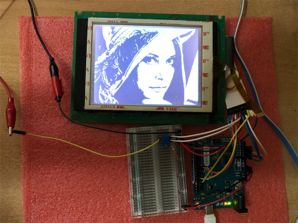
The author still can not understand how he managed to turn the picture (see which side of the train). Anyway, on the project page on GitHub there is this example.
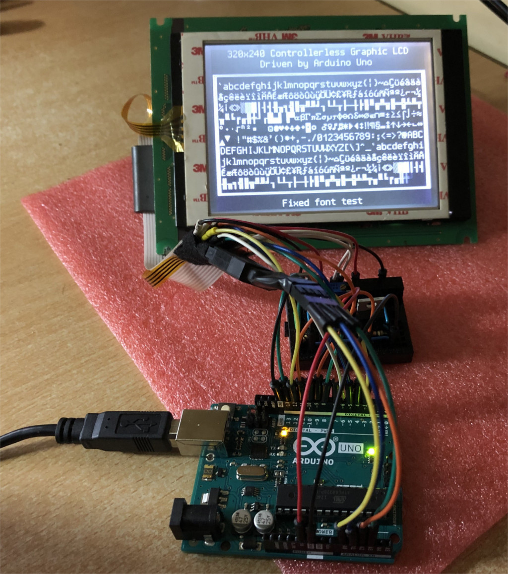
Text mode
But from the video ROM little sense, and 9600 bytes for video RAM in the Arduino is not. The text mode comes to the rescue, in which the character generator's ROM and video RAM combined have a smaller volume than video RAM in graphics mode. On this subject, supporters of the Republic of Kazakhstan and the "Specialist" can break spears endlessly.
A short example in AVR assembly language:
... lpm r24, Z ;---------- (CL2 rising edge) out %[data_port], r24 ld r30, X+ swap r24; (CL2 rising edge) out %[data_port], r24 lpm r24, Z ;---------- (CL2 rising edge) out %[data_port], r24 ... Required "iron"
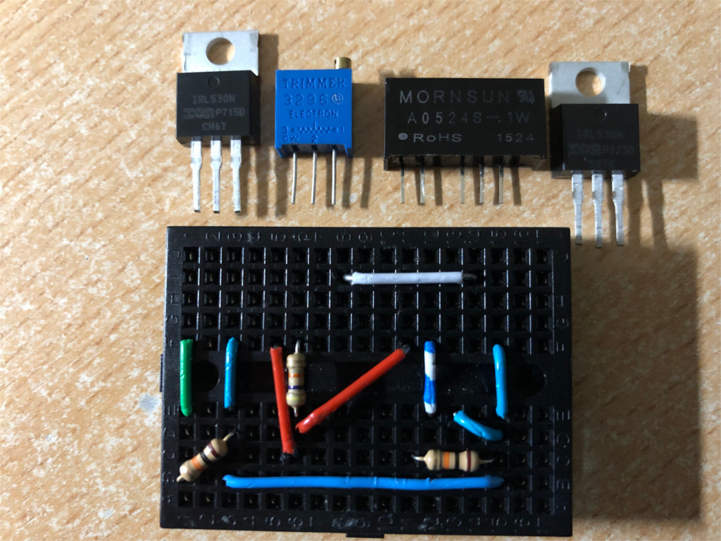
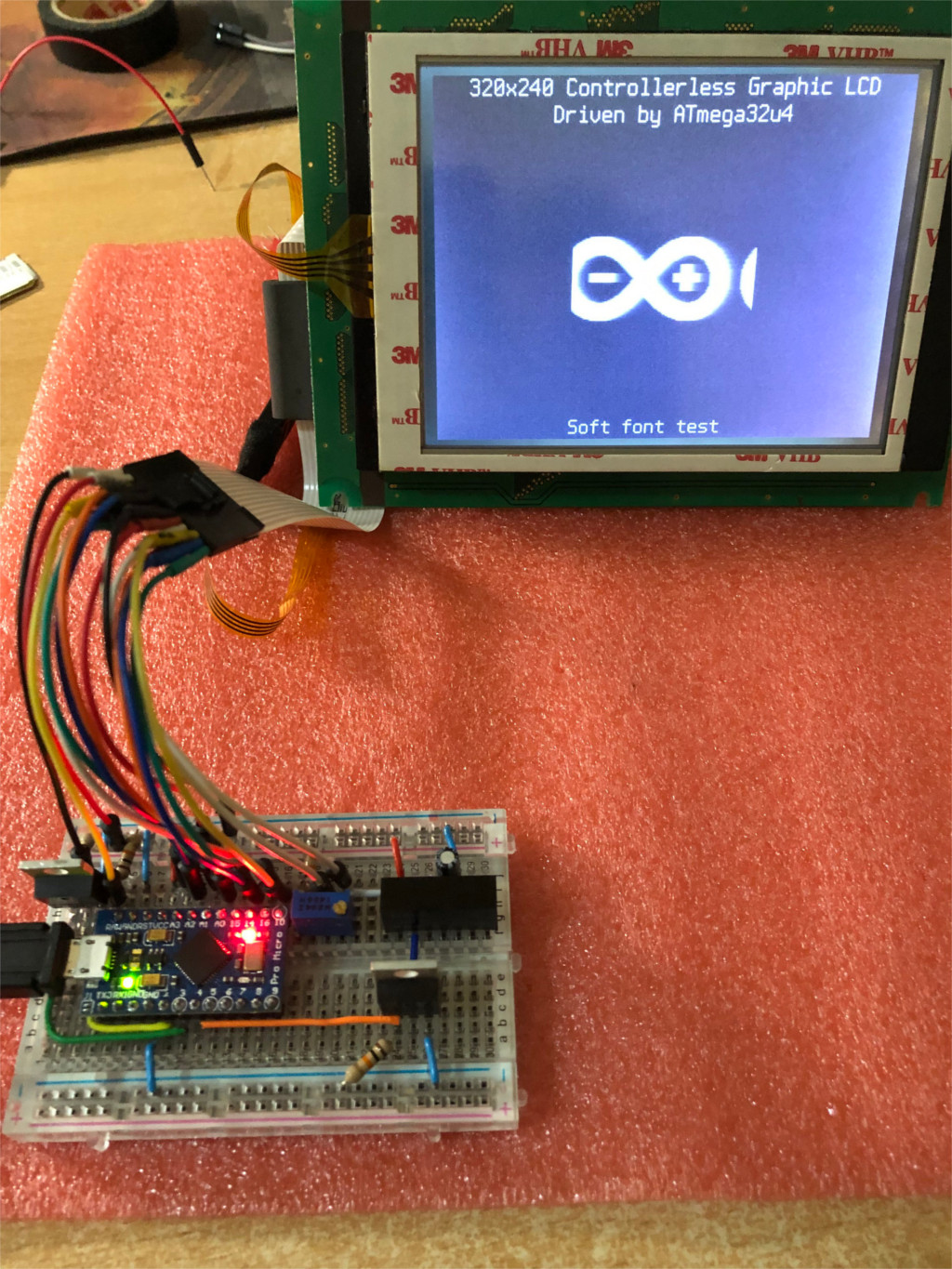
For the module F-51543NFU-LW-ADN / PWB51543C-2-V0, the author has applied:
Arduino on AVR with a clock frequency of 16 MHz (tested on Uno, Leonardo and a clone similar to ProMicro).
Negative voltage source. The author has it - unstabilized DC-DC converter A0524S-1W with input and output decoupling. Converters for the MC34063 will also work (this chip is very easy to find - just disassemble the cheapest USB charger for the cigarette lighter) or MAX749. Stabilization is not required, the range of allowable voltages for this input of the module applied here is quite wide. The nominal is minus 24 V, the maximum is minus 30 relative to the common wire and 35 between Vdd and Vee. Current consumption is 6 mA.
Two N-channel MOSFETs with logic level control. The author has applied IRL530n, the stock, of course, is large, but it definitely will not burn out. One transistor controls the backlight, the other - a source of negative voltage.
A 250 kΩ trimming resistor for applying voltage to the V0 input. Expose that the moving contact is -16.8 V at a temperature of +25 ° C. This is from datasheet, and so, of course, such accuracy is not needed.
Several 10-kilohm resistors to pull up.
Layout and jumpers.
What to do now? QR clock? Ask kote:
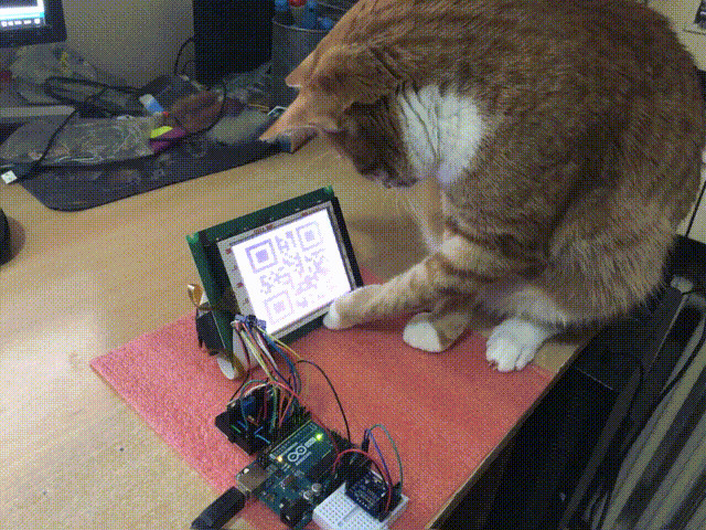
Kote offers to implement a simulation of some common LCD with a controller. So that the Arduino can be connected to another, “thinking”, that works with the display on the HD44780, only large.
Font - also in RAM
Take the example of EGA and VGA - there it is done that way when working in text mode. Only here the signs fit only 64, but at least that’s how it fit into the RAM, unlike the graphics mode. True, the main cycle of events slowed down, but you can try tile graphics:
Graphic mode and halftones
In the Arduino on the AVR so much RAM is not, and the point. Even in Mega. 320x240 even with one bit per pixel is already 9600 bytes. A total of four semitones will require twice as much. With external RAM, for example, 23LC512 in SQI mode, you can try to implement something similar to DMA, but it's easier and more profitable to remake everything on ESP32, where there is more static RAM and DMA is easier done.
If you just want to connect such a display to a PC via USB, you can try using ATmega32u4 for this - there are enough resources even for gradations of brightness (with the help of FRC, what it is, as described in my previous translation). But not in the "mega" used as an interface converter, but in the PC, which will itself scan the LCD on the fly at a speed of 5.4 megabits per second.
When the module was still in the tape library, there was both a GUI and brightness gradations — everything was there.
Updates will be. In the meantime ...
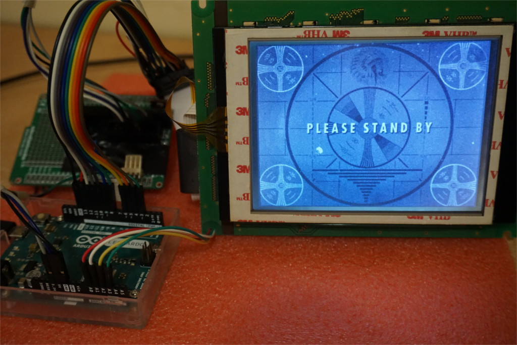
And this is not a photo montage, but the result of PC control. And we will move from Hackaday.io to GitHub - there are still a lot of interesting things in README.md.
Signals to control such modules
FLM - First Line Marker - the first line marker, may also be called FRAME, VSYNC, etc.
CL1 - Row latch pulse - the impulse to write a row, may also be called. LOAD, HSYNC, etc.
CL2 - Pixel shift clock - pixel shift pulse, can also be called. CP (change pixel), etc.
M - alternating signal, due to which the pixels are controlled by alternating voltage, can also be called BIAS (offset), etc.
D0-D3 is a four-bit parallel data bus.
Common wire, backlight power (for example, VLED ±), module power (VEE and V0)
Do not neglect datasheets. The module may require another negative voltage, or it may be positive, or the converter may be embedded. The logic may differ, for example, if the unit on CL1 does not have a reaction on CL2. There may be another backlight (CCFL (caution, “bite-cutter” inverter) instead of LEDs), or there is no pin on the board, then you just won’t recognize it without datasheet. It is impossible to connect anything at random.
What is there to do
Send the string in chunks of four bits, the record is made on the decline on the line CL2. Having passed a string, write it down in a decay on the CL1 line (yeah, after all, there is a bit of RAM in the module — one line). The next line will be selected automatically. Having transmitted the entire frame, return to the beginning using the FLM signal. There is an example in the datasheet on LC79401. Record to produce with sufficient speed, pulses on CL1 to apply evenly. The controller hesitated a little - the screen blinked ugly.
After each frame, change the logic level at the input M to the opposite, so that the pixels are controlled by an alternating voltage. Otherwise, the display deteriorates:
This operation can not trust the microcontroller, and put the counting trigger. The entrance to the FLM, the output to M - in general, is understandable.
An example for outputting an image from flash memory (see the beginning of the article) is called clglcd_simple in this repository.
As already mentioned, it is impossible to do the same with the RAM in the Arduino on the AVR - it is not enough, therefore ...
And again - text mode
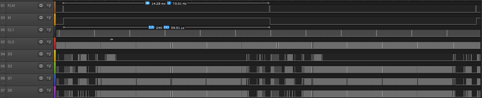
According to the datasheet, you can transfer data on a four-bit bus and “pull” CL2 with a frequency of up to 6 MHz. Therefore, you can quickly and quickly pass a string, then the microcontroller will solve other tasks for a bit, but as a timer it will “tell” it - it will “pull” CL1 and repeat the cycle.
When generating characters for a horizontal resolution of 320 pixels, all this can be done in 20 µs (320 pixels / 4 bits = 80 pulses, CL2 is “jerked” at a frequency of 4 MHz). The remaining tasks remain 39.5 µs. CL1 "pull" every 59.5 µs and get a frame rate of 70 Hz. Well, there will be more interrupt handling procedures and so on, in general, the microcontroller will be busy managing the display 45% of the time. "Whole" 45 or "total" 45? Probably the second: you can quickly overwrite the data in the video RAM.
Want the microcontroller to spend less time managing the indicator, and more on other tasks? You can reduce the frame rate to 50 Hz, you can overclock the microcontroller to 20 MHz. In either of these ways, more cycles will take place between interrupt handling routines.
The output comparison timer switches the CL2 line every four clock pulses with a duty cycle of 50%. At the same time, the data arrive at the outputs of the PORTB port connected to the four-bit data bus of the module in such a way that their change occurs at the time of the level increase on CL2, and at the time of the decline they remain unchanged. Of course, you cannot do this without an assembler:
... lpm r24, Z ;---------- (CL2 rising edge) out %[data_port], r24 ld r30, X+ swap r24; (CL2 rising edge) out %[data_port], r24 lpm r24, Z ;---------- (CL2 rising edge) out %[data_port], r24 ... 8 cycles - and transferred four nibble. And what exactly to transfer depends on which character is in the corresponding cell of the video RAM, which pixels corresponding to this symbol should be transferred from the character generator's ROM, and what is stored in the corresponding cells of this ROM.
The most inconvenient here is the need to stop the timer after exactly 80 pulses. Some timers, such as Timer4 at 32u4, cannot do this.
To obtain the signal supplied to the CL1 line, the author used another output of the microcontroller, designed for both the timer and fast PWM. What of this applied here, of course. It switches every 952 bars. Or, if we count after the clock divider by 8, it is obtained every 119 pulses. At this point, the interrupt handling procedure is started and causes the microcontroller to send new data to the control lines, which will be needed during the next pulse on CL1. Well, the level on line M changes with half the frequency. And the LCD does not deteriorate. All signals together look like this:
The character generator consists of 256 characters - enough for 866, KOI-8R or 1251. 40xN characters are placed in the video RAM, where N is the number of lines depending on the character height. The width of the symbol is always 8 pixels, and the height can be 6, 8, 10, 12, 15, 16. The smaller it is, the less ROM is required for the character generator and the more video RAM. With an 8x8 font (40 characters per 30 lines), 1200 bytes of RAM and 2048 bytes of ROM are required. When the font is 8x16 (this module looks best), RAM is 600 bytes, and the ROM is 4096. From the translator: you can store the font as 8x8, and vertically scale twice as software, and bypass 600 bytes of RAM and 2048 - ROM. In order to store several fonts in ROM, you need to keep the address of the beginning of the font not in a constant, but in a variable, but you will not be able to display the text in several fonts at once, unless, of course, you change the address on the fly by the interrupt handling procedure directly during the transfer of pixels to the display.
The font is stored as follows: first, the top lines of all 256 characters, then one line below, and so on. In the misc folder of the repository there is a Python script that automatically converts the TTF font to the header file clglcd_font.h with the PROGMEM array in the required format. Classic pixel fonts under CC-BY-SA 4.0 can be found here .
And again - take the example of EGA and VGA
But this time with details. The character generator in RAM, as indicated above, contains only 64 characters, they can be designated with numbers from 0 to n or from 255-n to 255. They are stored in the same way: the top lines of all characters, then the following, and so on. Only all this is aligned, taking into account the fact that the characters are not 256, but 64. For characters of 8x16 pixels, 16 * 64 = 1024 bytes are required. The repository has an example of working with a character generator in RAM.
If both character generators are used at the same time - 256-character in ROM and 64-character in RAM, you will have to accept the fact that not only less RAM is left, but the data transfer rate of the lines to the module will decrease - instead of 8 cycles of loading two nibbles it will take 12, that is, not 20 μs, but 30, but instead of 45% of the time it takes 60 to control the LCD.
Graphic mode with semitones
As stated above, in this case the microcontroller works simply as an interface converter. ATmega32u4 is required, and what to do is described here . Please note that the module may deteriorate due to the program hanging on the PC.
So what is this four-wire cable - from a resistive sensor, it turns out.
Where to connect
As stated above, a negative voltage is required, which in the first experiments can be removed from three “Kron”, and then a converter is assembled, for example, on MAX749. The power control signals, as well as the DISPOFF signal (this is an inverse signal, the module is turned on at one) pull the resistors down. During the firmware and reset of the microcontroller, the appearance of logical units there is unacceptable.
The negative voltage is applied after the + 5V voltage, and the logical unit to the DISPOFF line - when data is already present on the control lines: at least one unit on the data bus, one unit on CL1. Otherwise, the module may fail.
Inputs D0-D3 can be connected to the outputs of the same microcontroller port, for example, Px4-Px7, while the outputs Px0-Px3 cannot be used as a GPIO. You can assign other functions to them, for example, use them as timer outputs, a serial interface, and so on. If you use them as inputs, be careful: the built-in pull-up resistors can switch arbitrarily if they are not disabled (PUD - pull-up disable).
Input M - to the output of the comparison timer or PWM.
CL1 input - to another output of the same timer.
CL2 input - to the output of another comparison timer.
FLM - to any digital output.
DISPOFF - to any other digital output.
The rest depends on how you power the module. The author prefers to control the backlight and Vee separately.
How to use the firmware
Place clglcd.h and clglcd.cpp files in the sketch
Make a backup copy of the clglcd_config.h file and edit it, taking into account what is connected to, as well as what functions you need: character generator in RAM, etc. Attention, the code does not indicate the names of the Arduino outputs, but the names of the outputs of the microcontroller according to the datasheet. The names of the outputs of the comparison timers are as follows: for example, 2, B is OC2B, which corresponds to PD3 on Arduino Uno. The examples show the connection options that have earned the author.
Generate the font file clglcd_font.h with the Python script in the misc folder (see above).
See in the examples how to initialize, turn on and off the display. Place in the screen array the text that you want to display for verification.
Compile and fill in the sketch. Check with the logic analyzer that the correct signals will go to the display, and with a voltmeter that all the supply voltages are normal. Only then connect the display.
Add a code to the sketch that will do something, for example, receive text on the serial port and display it.
Interrupts when the display is on
Update the display must be constantly, what are the procedures for handling interrupts. If the interrupts stop for more than 30 µs, the display will start blinking, and if it’s more than 60 µs with a unit on the FLM line, it can fail. If it is necessary to stop interruptions for a long time, first turn off the display with the DISPOFF signal (I repeat, this is an inverse signal, the module is turned on at one). Of course, if it turns off for two seconds every time you need to process data from a humidity and temperature sensor, few people will like it, but it’s better than to spoil the module. It is even better to entrust everything else to a separate microcontroller. Especially, information exchange by the same microcontroller with devices operating under the 1-wire protocol and address LEDs is unacceptable. Arduino Pro Micro clones are inexpensive enough to buy two.
Connection
But hardware-implemented interfaces will work fine: serial ports, I 2 C bus, SPI bus in master mode. In the slave - only if the master device allows periodic slapping of the slave for 25-35 µs. Of course, it still depends on how many “legs” are left unoccupied after connecting the display.
A 32u4 USB works fine if you don’t interrogate the endpoint management too often (slow interrupt handling procedure code). The CDC driver and its API were fast enough.
Further in the README.md file on GitHub, the list of similar projects is repeated, the same as on the project page on Hackaday.io
Thanks for attention!
Source: https://habr.com/ru/post/444912/
All Articles