CSTroN - a homemade monitor on a vintage CSTN-matrix with a VGA-input and control board on the FPGA
What if TFT never invented? LCD monitor with CSTN-matrix
Introduction
When CRT monitors prevailed, the following argument was put forward in their favor: despite all the improvements, LCD displays never outperform pipe imaging. They, as before, will be used only where energy efficiency and small thickness are required [1]. Decades have passed, and now we know whether the proponents of this argument were right. But today it is interesting to look at the LCDs of that time: are they really so low-quality? What is it like to look at the CSTN matrix in 2019?
')
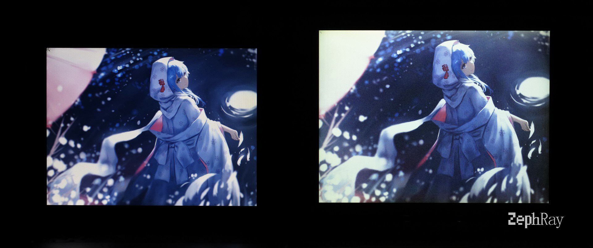
Left TFT, right CSTN, both displays from the nineties
LCD in the last century
Before switching to TFT, a variety of display technologies were used in portable computers. At first, they used the same CRT monitors as desktop computers, only smaller ones. For example, in Compaq Portable (1983), IBM 5155 (1984) or Commodore SX-64 (also 1984).
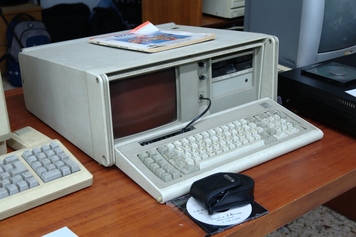
IBM 5155, author: Soupmeister, license: CC-BY-SA-2.0, from here
Carrying such a PC with you everywhere was hard, a completely different thing - a laptop with TN-LCD (twist nematic), for example, IBM 5140 (1986), Toshiba T1000 (1987). These displays have low contrast and viewing angle.
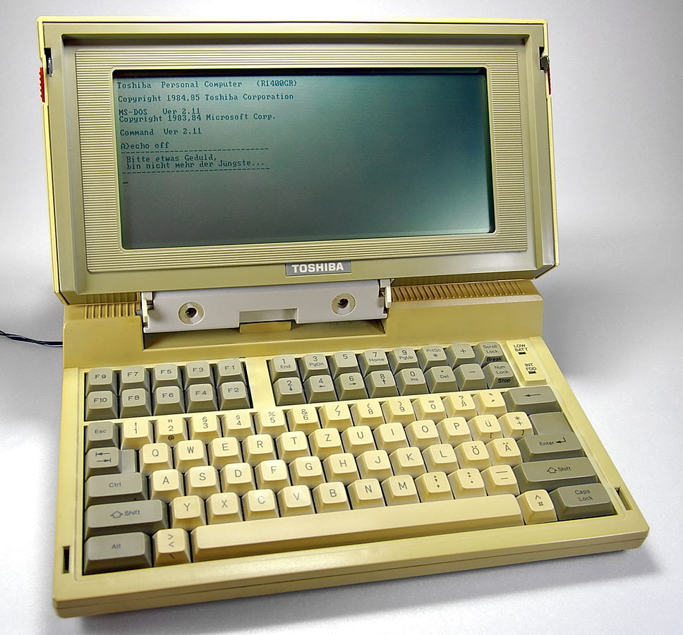
Toshiba T1100 with a monochrome TN-display, author: Johann H. Addicks, license: GFDL, hence , the link is broken, in the original too
Some manufacturers have experimented with gas discharge matrices, so Toshiba T3200 (1987) and IBM PS / 2 P70 (1991) laptops saw the light. They provided high contrast and several shades of brightness in red-orange light, but they were quite expensive. Finally, STN-LCDs (supertwist nematic) were developed, as, for example, in MS1504 Electronics and its Toshiba T1100 prototype. The contrast was much better - from 1: 5 to 1:50, and several gradations of brightness were enough for business applications (using a laptop in everyday life was still too expensive). But what if the user wants a color image? In this case, he was offered two technologies: TFT and CSTN (color supertwist nematic). The first notebook with TFT - NEC PC9801NC - was introduced in 1990, the image quality for those years was above all praise, but it cost “such a toy” much more than other, and so expensive, portable computers. Well, the CSTN-display is just an STN-display, which is superimposed on the filter. For a long time, matrices of both types were used in laptops. And in the cars of the New York subway CSTN-monitors are still working.
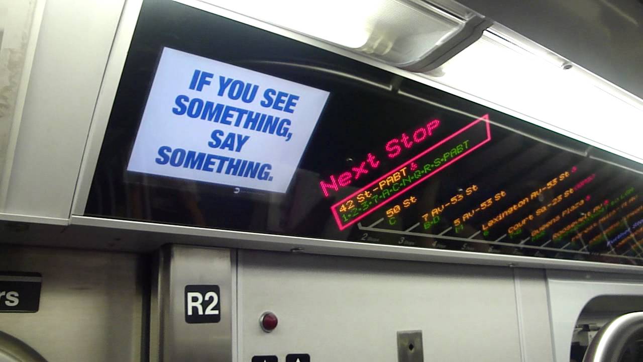
One of them, source: Transit + PLUS
CSTroN
The author wanted to look at the CSTN-display. How? For starters, just buy an old laptop with it and use it. It was AMD 5x86-P133 processor. That is, the most dynamic thing that can be run on it is DOS games (oh well, he and MPEG1 will pull in the program QV - translator). Of course, it’s great to play them, but I wanted to see how YouTube, for example, looks on such a display or a modern game - but this is impossible.
Or?
In general, you need to somehow add a VGA or HDMI input to it - and you can send a signal from something modern. TFT screens from laptops are often converted into monitors quite often. Just buy a fee that fits the matrix - and that's it. And you can make your own prefix on the FPGA, which converts a VGA or HDMI signal into a stream of data about pixels.
Some time ago, motherboards were also released to turn CSTN matrixes into VGA monitors, but this is no longer to be found. But you can adapt for this debug board on the ML505 FPGA.
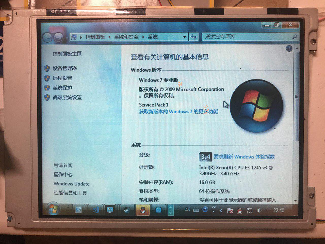
The finished result. It is rather unusual to observe this on the CSTN-display: 16 GB of RAM.
Matrix Management
Let's start with the basics. Like any matrix display, the CSTN display has rows and columns. Have you ever led a microcontroller LED array? Here is the same, but the stresses are variable. You need to send certain signals to both selected and unselected rows and columns - and the pixel at the intersection of the selected row and column will show what you need. The shape of the signals is quite complex, the mean square voltage value, the phase shift between the voltages on the row and the column, and the offset are important ... And so, pixel by pixel, an image is formed.
Fortunately, the FPGA is not required to generate all these signals, and even on such a huge number of lines. All this is done by the module built into the display. There the pulse converter increases the constant voltage, it passes through the divider and the repeater, this is how the bias voltage is obtained. Row and column drivers transform this voltage into a variable of the required form. All that is required is to submit a stream of data about the state of pixels to the display module.
On TFT-LCD with DPI (digital parallel interface) interface, all data on one pixel are received at once in one clock cycle. On the line of horizontal and vertical synchronization, pulses arrive after each, respectively, line and frame. Pixels are simply continuously transmitted line by line, frame by frame. If the transfer of a full frame takes 1/60 s, then the refresh rate is 60 Hz. The data bus width is equal to the color depth in bits, usually 16 (5 bits for red and blue, 6 for green), 18 (6 bits for each of the colors), or 24 (8 bits for each of the colors). LVDS is the same thing, only the bits are transmitted not in parallel, but in series along the differential pairs, but in MIPI DSI they are also combined into packets. The SPI / i80 bus allows you to send various commands to the controller, and the one that executes them generates signals for a DPI or similar interface. Which, in turn, is somewhat similar to VGA, only the data on the brightness of each of the colors do not come in analog, but in digital form. There are VGA to DPI converters and back. The boards are very convenient, allowing to receive a VGA-signal from the Raspberry Pi, although initially this computer produces only HDMI and composite video.
The display module of the CSTN-matrix should be given signals that are very similar to those supplied to the TFT-matrix with the DPI interface. The datasheet on the SX21V001 [2] shows how to control a CSTN display with a resolution of 640x480:
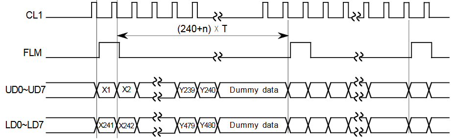
Here is the transfer of the whole frame. The signal comes to the CL1 line after each line, to the FLM - after each frame. And there is a data bus of 16 lines. Actually, in this figure, an error was made: during the transmission of the first and second lines, data Y1 and Y2 are received along the lines UD0-UD7, but not X1 and X2, and along LD0-LD8 - Y241 and Y242, respectively. Here, U and L are, respectively, upper and lower, that is, the display consists of two matrices with a resolution of 640x240, one above the other. Here it is, the mysterious "dual scan" from the old laptop advertising, from which the horizontal bar comes across the entire screen. In STN and CSTN displays, the contrast is inversely proportional to the number of rows, so this separation allows it to be increased. But this is not the only way in which they differ in control from TFT.
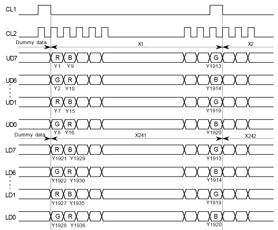
It is not clear why the horizontal axis here was called Y ... But in any case, CL2 here is a line for supplying clock pulses switching pixels. But for the UD and LD buses, in a single clock cycle, not data about one multi-bit pixel, as in a TFT, is transmitted, but data about several pixels at once, three bits for each. One bit per color, three bits per pixel — eight colors in all.
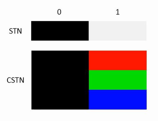
But how so? It is clear that the number of colors in CSTN-displays is small, for example, 4096 or 32768, but not 8. It turns out that PWM is used here. Light-emitting diodes are controlled in this way, which means that LCD pixels are also possible. We need, for example, a brightness of 50% - we turn on a pixel in even frames and turn it off in odd frames. This method is called FRC (frame rate control), well, in this context, PWM is called pixel brightness control in the same way, but within not one or more frames, but one. The FRC performs the external device, and the PWM implements the chips in the display module, if there is support for this function. The author does not know CSTN displays with PWM, but he assumes that these are HPA-type matrices. In any case, since PWM is not available, the required color depth can be obtained using FRC.
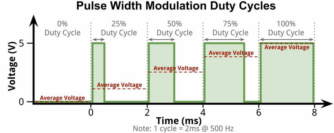
The price of this will be flickering, so there are monstrous (compared to TFT) frame rates in CSTN displays. For example, in this module initially was 120 Hz, and the author overclocked it to 240.
How it was implemented
The developer had several difficulties at once:
- the input signal has a frame rate of 60 Hz, it should be doubled or even quadrupled
- in the input signal, the frame is not divided into upper and lower halves of 640x240 pixels each, but here it is necessary to divide
- and still need to implement FRC, otherwise the color depth will be 3 bits per pixel
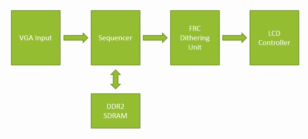
The first two points mean that a framebuffer is needed, and not simple, but a two-port one. Well, the third problem is solved using the GLDP LUT (grayscale-level display pattern lookup table) [3]. The lookup table has two types of input data: the color to be displayed and the state of the frame counter. And one kind of output data: those three bits that need to be sent to the subpixels of one or another pixel at the moment. Hence, the following nodes will be required:
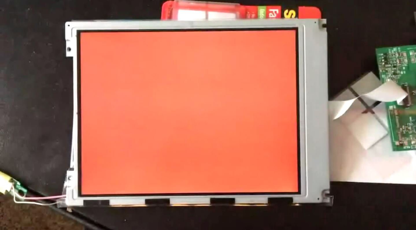
The first step is to fill the entire screen with some color. At this stage, it is not necessary to know where a pixel is, it is enough to make sure that the display module supplies signals of the required shape to the matrix. The code for the fill in the FPGA is here .
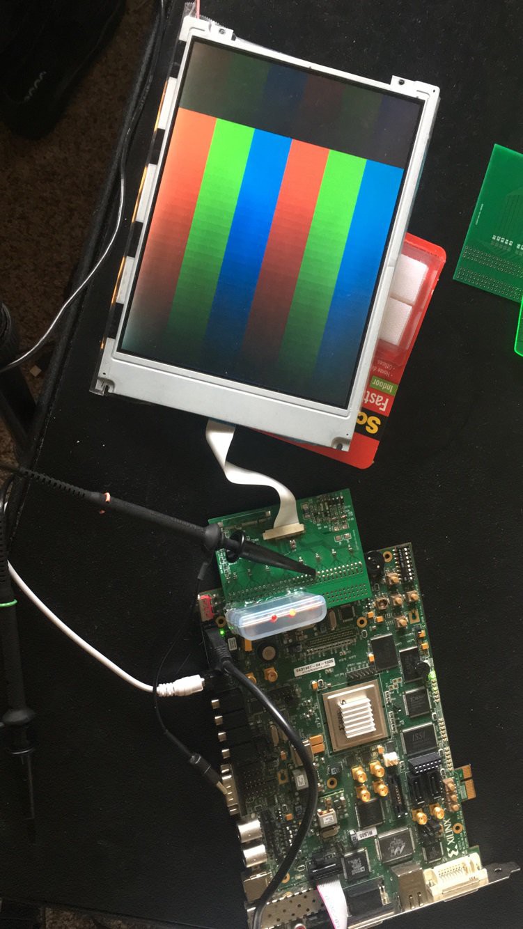
Now we will try to display something, and with incomplete brightness as well. Looking for such lookup tables for FRC to minimize flicker. The author came up with two tables that are applied to the pixels in staggered order. Therefore, every two adjacent pixels flicker out of sync. The code is here .
So, to show the image we have already “taught” the board, the next thing you need is a framebuffer. With 640x480 and 5 bits for each of the colors, its volume will be about 600 kilobytes. Not much, but there is not so much in FPGA. Well, the board has DDR2 RAM and Xilinx MIG for managing it. Two FIFOs are implemented, one for reading, the other for writing. The arbitrator decides whether the next data exchange with DDR2 will be reading or writing. There are two buffers, the recording goes to one, reading from another, and when changing frames, they are swapped. Referee code is here .
It remains to realize the video capture, in one of the previous projects of the author there is already a similar development, after completion the converter code from VGA to DPI has become like this .
And what happened?
Look!
For the author, this is the third project on the FPGA, it was interesting to work with the Xilinx MIG and DDR2, as well as with a simple conveyor. A better FRC with delta-sigma modulation is planned, as well as experiments with later CSTN panels using Sharp's HPA (High Performance Addressing) technology.
Thanks for attention!
Sources
1. Li, W., & Guo, Q. (2000). Liquid Crystal Display Application Technology. Beijing: Electrical Industry Press.
2. HITACHI (1999). SX21V001-Z4 Customer's Acceptance Specifications.
3. Hsueh, Y., & Lee, J. (2008). Image improvement method for LCD frame rate controller. 2008 IEEE International Symposium on Consumer Electronics. doi: 10.1109 / isce.2008.4.4959534
Source: https://habr.com/ru/post/444762/
All Articles