CNC machine from what was lying around in the garage
I assemble another portal-milling machine with a small working field on wood, plastic, composites. About this story is given under the cut ...
I will say right away - not everyone has fallen in the garage of what I have. Due to some third-party mechanical projects, I have accumulated some trash, which later could just rust, after which, it is only in black metal. I attributed to this type of trash polished guide shafts, some scraps of duralumin sheets (although they will not rust, they take up space). I also had a stepper motor and a driver.
In addition, from the main one it was necessary to retrofit my existing set: ball screws, carriages for guide shafts, motors, electronics and a spindle. In general, “very little”. And with all of this, apart from all small things in the form of metalworking and various hardware, I will get a CNC machine.
')
Having estimated the price tag for the missing components, and realizing that I could manage such a sum without any special financial difficulties (especially if you didn’t buy everything right away, but as far as assembling), I still decided on such a rash step and started designing the future machine.
Based on the lengths of the guides and the size of the scraps of duralumin (since they were just about the same size), he began by drawing the base.
Dimensions:
Trimming - length 700mm, height 70mm, thickness 6 mm.
Guides (4 pieces) - diameter 25mm, length 740mm.
From these dimensions and repelled during the construction of the whole structure. Accordingly, the length of the portal movement along the base turned out to be 600 mm (X coordinate).
Due to the fact that there are only 4 guides, but they were not planned to re-buy them, and besides, the machine has three axes of movement, we had to divide two guides into two smaller axes: Y and Z. I divided it so that the width of the working field along Y turned out to be 250mm , and on Z - 80mm.
Since this is not my first project of a CNC machine, instead of the usual KOMPAS 3D, I used SolidWorks. All the standard parts I have available and ordered (engines, couplings, carriage guides, bearing bearings, ball screws, rail supports) that do not require additional processing were redrawn. Then he began to add guides to the project, began to bind them with duralumin sheets, in which he made technological holes for mounting and installing engines, and reinforcing supports.
Speaking of the latter. As a money saving, support for the guides could not be set, but since the sheet thickness is too small in my mind, I thought that such supports would greatly enhance the design.
The portal itself was decided to be moved by installing two ballscrews at the edges, rather than one in the center, although this is a bit more expensive, but there is no need to worry about the weight of the portal.
After the base was ready, I began to draw the portal. I painted the main beam, which will carry the portal and move it along the whole base. The beam turned out to be quite strong due to parallel plates fastened and pulled together by cylindrical axes. The main plane of attachment to the carriages interfaced with the plates forming the gantry stand. He strengthened them with a sheet thickness of 6mm (he was in my garage too). Everything else was painted the same way as the base.
Attaching the carriage guides and the ball screw to the project along the Y axis, I threw the mechanism for moving the Z axis. It has already used the T-shaped supports of the guides, and the end plate is attached to the guide carriages, which mates with the spindle.
I want to make a small digression and tell about my use of cylindrical guides. I know that some “experts” in the comments will say that these guides will bend, the accuracy will be bad, the rigidity of the structure is also none and everything like that. For the processing of the materials for which this machine is made and when using such a diameter of the guides, for such a length as mine, the deflection will be insignificant, rigidity is more than enough.
Throughout the design, I used ball screws with a diameter of 16mm in 5mm increments.
After drawing the power frame of the machine, he added several auxiliary elements to it, such as the corners on which the flexible cable channel and supports should be attached to the base of the machine.
Production of parts for the machine began in the same sequence in which they were painted. I processed the parts from scrap and sheet duralumin on my last project - a CNC machine tool. I will say right away, if you count in the aggregate, then it took no more than 8 hours to process all flat parts. I spent more time selecting the cutting mode and waiting for several cutters I needed.
Basically I used a single mill cutter with a diameter of 6mm, as well as for two small openings with a diameter of 3mm. Of course, there were no broken cutters, but in the end it’s an experience, though not as cheap as we would like.
The guides and tails of the ballscrews were trimmed by my friends, and there, too, was not without jambs. It's all the little things, it happens when a person drank hard all his life, and then abruptly threw.
The machine was going to as a designer, it seems that I did not play enough at one time and now I am filling it in with the assembly and design of the machines. It's nice when all the parts fit together and almost no need to refine and customize them. However, it was necessary to refine. There was a difficulty with the mating of engines and ballscrews.
Ordering an additional three engines similar to the one I already had, as well as 4 couplings for connecting the shafts of engines and ballscrews. When everything ordered came, it turned out that the diameter of the output shafts of the engines was 6.2 mm, and the couplings arrived with holes 8 and 12 mm, which is necessary, since the output shaft I had in my engine had 8 mm. In the end, I ordered three new couplings with a diameter of 6 and 12 mm, after which I simply drilled a hole to 6.2 mm.
It remains unclear why the motor shaft is 0.2 mm larger and what they have in general for such standards, or does it all depend on a specific manufacturer, what bar was available such as a shaft and decided to use?
Be careful when ordering.
The mechanical part is almost ready, now you can go to the electric one. Engines connected to the drivers. Two engines of the X axis, connected in parallel to one DM542 driver, the other connected to cheaper drivers (untitled) based on TB6600. All three drivers were connected to the DDCSV2.1 controller on 4 axes, only the fourth axis, namely the rotary one, cannot be assigned as duplicating any of the three main ones. Together with the controller in the kit was an MPG remote control for manual control of coordinates - a cool thing. I think that in the future she will not be at ease with me and will continue to delight me.
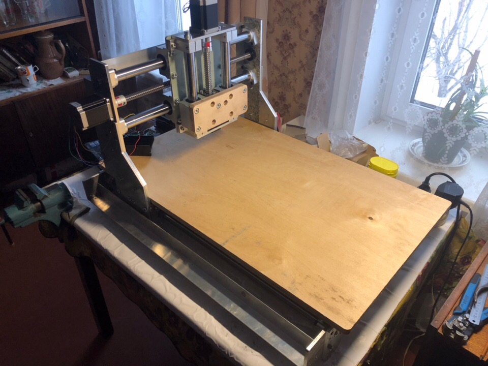
At the moment, made a hinged installation and did not stretch the normal wires, and the parts are not all bought. Actually connected to check the performance of mechanics. The other day, only ordered a 1.5 kW air cooling spindle. and frequency converter with collet.
In the future, install the spindle, and I will breed wires; I will manufacture and assemble the box under the electronics.
In the final part, I will show and tell you what kind of a beast I got, let's talk about its pros and cons and draw conclusions.
Thank you for your attention and enjoy reading!
Project 1
Project 2
I will say right away - not everyone has fallen in the garage of what I have. Due to some third-party mechanical projects, I have accumulated some trash, which later could just rust, after which, it is only in black metal. I attributed to this type of trash polished guide shafts, some scraps of duralumin sheets (although they will not rust, they take up space). I also had a stepper motor and a driver.
In addition, from the main one it was necessary to retrofit my existing set: ball screws, carriages for guide shafts, motors, electronics and a spindle. In general, “very little”. And with all of this, apart from all small things in the form of metalworking and various hardware, I will get a CNC machine.
')
Having estimated the price tag for the missing components, and realizing that I could manage such a sum without any special financial difficulties (especially if you didn’t buy everything right away, but as far as assembling), I still decided on such a rash step and started designing the future machine.
Based on the lengths of the guides and the size of the scraps of duralumin (since they were just about the same size), he began by drawing the base.
Dimensions:
Trimming - length 700mm, height 70mm, thickness 6 mm.
Guides (4 pieces) - diameter 25mm, length 740mm.
From these dimensions and repelled during the construction of the whole structure. Accordingly, the length of the portal movement along the base turned out to be 600 mm (X coordinate).
Due to the fact that there are only 4 guides, but they were not planned to re-buy them, and besides, the machine has three axes of movement, we had to divide two guides into two smaller axes: Y and Z. I divided it so that the width of the working field along Y turned out to be 250mm , and on Z - 80mm.
Since this is not my first project of a CNC machine, instead of the usual KOMPAS 3D, I used SolidWorks. All the standard parts I have available and ordered (engines, couplings, carriage guides, bearing bearings, ball screws, rail supports) that do not require additional processing were redrawn. Then he began to add guides to the project, began to bind them with duralumin sheets, in which he made technological holes for mounting and installing engines, and reinforcing supports.
Speaking of the latter. As a money saving, support for the guides could not be set, but since the sheet thickness is too small in my mind, I thought that such supports would greatly enhance the design.
The portal itself was decided to be moved by installing two ballscrews at the edges, rather than one in the center, although this is a bit more expensive, but there is no need to worry about the weight of the portal.
After the base was ready, I began to draw the portal. I painted the main beam, which will carry the portal and move it along the whole base. The beam turned out to be quite strong due to parallel plates fastened and pulled together by cylindrical axes. The main plane of attachment to the carriages interfaced with the plates forming the gantry stand. He strengthened them with a sheet thickness of 6mm (he was in my garage too). Everything else was painted the same way as the base.
Attaching the carriage guides and the ball screw to the project along the Y axis, I threw the mechanism for moving the Z axis. It has already used the T-shaped supports of the guides, and the end plate is attached to the guide carriages, which mates with the spindle.
I want to make a small digression and tell about my use of cylindrical guides. I know that some “experts” in the comments will say that these guides will bend, the accuracy will be bad, the rigidity of the structure is also none and everything like that. For the processing of the materials for which this machine is made and when using such a diameter of the guides, for such a length as mine, the deflection will be insignificant, rigidity is more than enough.
Throughout the design, I used ball screws with a diameter of 16mm in 5mm increments.
After drawing the power frame of the machine, he added several auxiliary elements to it, such as the corners on which the flexible cable channel and supports should be attached to the base of the machine.
Production of parts for the machine began in the same sequence in which they were painted. I processed the parts from scrap and sheet duralumin on my last project - a CNC machine tool. I will say right away, if you count in the aggregate, then it took no more than 8 hours to process all flat parts. I spent more time selecting the cutting mode and waiting for several cutters I needed.
Basically I used a single mill cutter with a diameter of 6mm, as well as for two small openings with a diameter of 3mm. Of course, there were no broken cutters, but in the end it’s an experience, though not as cheap as we would like.
The guides and tails of the ballscrews were trimmed by my friends, and there, too, was not without jambs. It's all the little things, it happens when a person drank hard all his life, and then abruptly threw.
The machine was going to as a designer, it seems that I did not play enough at one time and now I am filling it in with the assembly and design of the machines. It's nice when all the parts fit together and almost no need to refine and customize them. However, it was necessary to refine. There was a difficulty with the mating of engines and ballscrews.
Ordering an additional three engines similar to the one I already had, as well as 4 couplings for connecting the shafts of engines and ballscrews. When everything ordered came, it turned out that the diameter of the output shafts of the engines was 6.2 mm, and the couplings arrived with holes 8 and 12 mm, which is necessary, since the output shaft I had in my engine had 8 mm. In the end, I ordered three new couplings with a diameter of 6 and 12 mm, after which I simply drilled a hole to 6.2 mm.
It remains unclear why the motor shaft is 0.2 mm larger and what they have in general for such standards, or does it all depend on a specific manufacturer, what bar was available such as a shaft and decided to use?
Be careful when ordering.
The mechanical part is almost ready, now you can go to the electric one. Engines connected to the drivers. Two engines of the X axis, connected in parallel to one DM542 driver, the other connected to cheaper drivers (untitled) based on TB6600. All three drivers were connected to the DDCSV2.1 controller on 4 axes, only the fourth axis, namely the rotary one, cannot be assigned as duplicating any of the three main ones. Together with the controller in the kit was an MPG remote control for manual control of coordinates - a cool thing. I think that in the future she will not be at ease with me and will continue to delight me.
At the moment, made a hinged installation and did not stretch the normal wires, and the parts are not all bought. Actually connected to check the performance of mechanics. The other day, only ordered a 1.5 kW air cooling spindle. and frequency converter with collet.
In the future, install the spindle, and I will breed wires; I will manufacture and assemble the box under the electronics.
In the final part, I will show and tell you what kind of a beast I got, let's talk about its pros and cons and draw conclusions.
Thank you for your attention and enjoy reading!
Project 1
Project 2
Source: https://habr.com/ru/post/444760/
All Articles