Miniature Macintosh Plus
At the beginning of the home computer era, there was a company called Apple. She had just earned tremendous success with the Apple II line of computers, but in order to stay on top of the fast-growing computer market, she needed innovation. The company was already working on the Lisa line, which was inspired by mini-computers and was intended for business users, and therefore had a corresponding price, but for the average consumer, it seemed too expensive. As an additional project, Macintosh was developed, which was supposed to be the realization of the idea of a new generation of computers for people from the street and cost about $ 500. Steve Jobs took up the project, and under his leadership, hardware became more advanced, software received GUI instead of text interface, and the price soared to almost $ 2500. Although the equipment received for this price was a little disappointing, for example, it lacked graphics accelerators and sound capabilities that other machines had, but the price was justified by the software. The first Macintosh was the Mac 128K, and its success pushed for the creation of more advanced models of this compact Mac, in particular, the Macintosh 512K, Macintosh Plus and the Macintosh SE series.
Although the development of Macintosh took place around 1984, long before I began to understand computers, I have some weakness with the compact Macintosh: the first computer my parents bought was Macintosh Plus. Later, it was supplemented with a 20 MB SCSI hard drive, and on this machine I wrote my first programs in Basic. When I was still living in the Netherlands, I bought a broken SE / 30 machine and turned it into a Linux server, which nevertheless was able to run Mac software. However, I left this car in the Netherlands, and here, in Shanghai, I no longer have the classic Apple hardware.
Although it is obvious that in my daily life, Mac Plus I will not need it anymore, I liked the idea of having it on hand in case of nostalgia attacks. I may be able to get a small share of the Macintosh experience if I create a smaller copy of such a machine myself. If I already have some experience in creating smaller versions of old hardware , why not try this process to build the venerable Mac Plus?
')
Display
What should I use to build a similar machine? First, I had the idea to take a Raspberry Pi or something similar, add a 2.5-inch LCD screen, an emulator like a PCE or MiniVMac, print the case on a 3D printer and consider the work completed. But I do not think that this idea will justify itself: the car for my taste will not only be too big, but the project itself will be too simple. In the original Mac 128K, even when the end result was too low-powered, the developers managed to crank a couple of tricks to save money. The simple assembly of a replica from a standard "iron" is contrary to the spirit of the original design. Therefore, I went to Taobao for more exotic components!
I decided to start with the display. For its time, the Mac had a sufficiently high resolution screen, so it was very important to choose the right display. Usually, when it comes to choosing a display electronics market in China, the range is large. Unfortunately, the “large assortment” consists either of screens with a large resolution, but also large sizes, or small screens of small resolution. Ideally, I needed a resolution of 512x342 pixels; This is the native resolution of the Mac, and on such a display I can display everything without zooming. Unfortunately, there are no ready screens of such permission in the market; The closest analogue is something like 640x480. For some reason, the screens of this resolution are quite large: the smallest has a diagonal of 3.5 inches. So alas, if I want to make the Mac as small as possible, I’ll have to reduce the resolution.
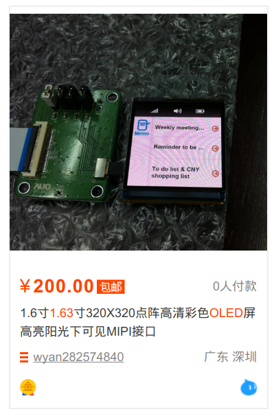
Having decided that it is quite possible to reduce the resolution a bit, I got an assortment of a fairly large set of displays. One of the first displays encountered was x163qln01 - a 1.63-inch OLED screen made by AUO. It is a bit expensive (about $ 25 per screen), but it can often be found on Taobao, and in the datasheet at least the contacts, dimensions, and power supply requirements are documented. It seems that this display was developed for some brand of smartwatch on Android, and a little googling, I even found some initiation sequences that can be used.
The only problem (except for the connector, which contacts are located at a distance of 0.5 mm from each other) was that the display does not use the parallel interface and not the SPI, but the MIPI interface. I will have to deal with this later.
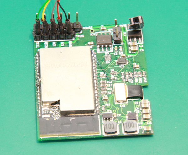
By selecting the display, you can go to the processor. I chose the ESP32-Wrover module. This module contains ESP32 (a WiFi chip with two 32-bit CPUs operating at 240 MHz and approximately half a megabyte of RAM), 4 MiB of flash memory and 4 MiB of PSRAM memory. I assumed that the two CPU cores would be fast enough to emulate a Mac and that I could use 4 MiB of PSRAM as Mac's RAM. Although 4 MiB of flash memory is not very much, they should be enough for the emulator plus a small hard disk with system software and programs. It’s good to me that I work in Espressif, so this equipment is familiar to me quite well; Besides, I can just take a few modules from work, instead of buying them and waiting for delivery.
So, everything is almost ready for work - the OLED-screen still needed components for power supply, therefore the number of components increased by a low voltage drop (LDO) stabilizer and other power supply chips. The Mac also needed sound, so I took a cheap accelerator chip and speaker, and I got a standard FT232 module for power and debugging. All these components are quite small and allow me to reduce the size of the device; the result should be a slightly larger model 1/6 of the real Mac.
Display control
Although I can not complain about the resolution, size and brightness of the display, but it turned out to be more difficult to display pixels on it. The MIPI interface was not supported by ESP32 silicon, so I needed to find another way to communicate with it. MIPI DSI is a standard developed by the MIPI Alliance and is not open; since this is a hobby for me, I had to collect crumbs of information from leaked documents and test existing devices. Fortunately, a year or two ago, Mike Harrison performed the reverse-engineering of the MIPI DSI interface used to manage iPod displays ( 1 , 2 , 3 , 4 , 5 , website ), and also found several copies of the specifications. It made my life much easier: at least, it would help me understand what to send to the display.
Although there is a lot more in the interface (and to find out about it, you should watch all the videos that I gave links to above), the physical MIPI layer is quite simple to explain. The MIPI protocol uses four wires: two data buses and two clock signals. It also has two modes of signal transmission: Low Power (LP) mode and High Speed (HS) mode.

In Low Power mode, wires are used separately to transfer control data structures, as well as to indicate that certain commands have a direct impact on the physical recipient from the other side. The voltage drop in this mode is quite large compared to the high-speed mode: for a high signal, the voltages are approximately 1.2 V, and for a low signal - approximately 0 V. Since the low power mode has more signal states, it performs functions such as sending the recipient of the order to switch to high-speed mode or exit from it. In the graph above, the blue lines show data transfer in Low Power mode.
In High Speed mode, two clock transmission buses (CLKP / CLKN), as well as two data buses (DP / DN) work as differential buses: one bus is always opposite to the other. The recipient detects the differences between the two tires and, based on them, sets the transmitted value: 1 if higher than DP, and 0 if higher than DN. As the name implies, High Speed mode provides very fast data transmissions up to 1.5 GHz. To achieve this without too much electromagnetic interference and power consumption, the standard applies the following trick: it uses very low voltages in this mode: the voltage on the pairs is on average 200 mV, with deviations of ± 100 mV per bus to indicate zeros and ones. In the graph shown above, the red bits are transmitted in high-speed mode.
From the point of view of transferring the data itself in high-speed mode, the interface can in fact be regarded as a rather strange and differential SPI interface: there is a clock signal and a data transmission channel, and at each clock cycle the data value is transmitted to the interface. The difference from SPI (except for the fact that the signals are differential) is that the data bit is transmitted only when the state of the CLK tires changes, and not only, for example, at the leading edge. Another difference is that the start of transmission is not recognized when the signal on the bus / CS becomes low, but an in-band signal: each data transfer starts with one unique “magic word” and the receiver determines this value in order to understand when the transmission begins.
To ensure that this interface interacts with ESP32, I will have to perform a level shift. I wanted to power the ESP32 from the 3.0 V source, so that all GPIOs would also have 3.0 or 0 V. To adapt this to the MIPI interface signal levels, I chose the lowest-cost solution: I just used resistor-divider networks.
To calculate the resistor values, I created the equations for the three output voltage states of interest (1.1 V for a high signal Low Power, 0.07 V for a low signal High Speed, 0.33 V for a high signal High Speed; voltages were chosen so so that in most cases remain within the specification) and the three input states that must generate them. I got the equations. Theoretically, it was possible to solve them manually, but in the end I threw them into WolframAlpha and got the required values for the resistors.
            3V
 G -R1 - + R3
 G -R2 - + - + ---->
            R4
            GND

 R4 * (1.9 / R1 + 1.9 / R3) = 1.1,
 (1 / (1 / R4 + 1 / R1 + 1 / R2)) * (2.93 / R3) = 0.07,
 (1 / (1 / R4 + 1 / R1)) * 2.67 * (1 / R3 + 1 / R2) = 0.33,
 R2 = 1000

 R1 = 280, R2 = 1K, R3 = 3K6, R4 = 150
At that moment, I realized that I could still cheat a bit: since in high-speed mode, the tires are differential, the display will only look at the difference between the two buses to determine the transmitted data. This means that I can save GPIO by keeping a fixed voltage on one of the buses and applying a high or low signal to another. For this, I needed a second type of network of resistors:
            3V
            R3
 G-R1 - + - + ---->
            R4
            GND

 R4 * (1.9 / R1 + 1.9 / R3) = 1.1,
 (1 / (1 / R4 + 1 / R1)) * (2.8 / R3) = 0.2,
 R4 = 150

 R1 = 320, R3 = 1500, R4 = 150
Another challenge was to create a clock circuit. Normal SPI transmits a bit at the leading edge of the clock bus. (Or in the rear, depending on the configuration.) MIPI transmits the bit on both the leading and trailing edges of the clock signal. Although the ESP32 equipment's SPI module cannot generate such signals by itself, we can convert one to the other using a simple D-flip-flop, the inverted output of which will be connected to the input. Each clock pulse at the input will change the output level, as we need.
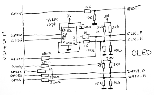
Schematic diagram
Having dealt with the display equipment, we are done with the most difficult part. Now we just need to add everything else. Let's start with the power source. It's pretty simple: I feed the entire 5V circuit from a USB-to-serial converter, which can also be used as a debugging / programming interface. This voltage is taken to generate +4.6 V, -3.4 V and 1.8 V, required by the OLED screen, as well as 3.0 V to power the ESP32. Voltages of +4.6 V and -3.4 V are generated by the TPS65631 chip, and a reference diagram for this is provided in the datasheet OLED display. Other voltages are generated by a pair of simple LDOs.

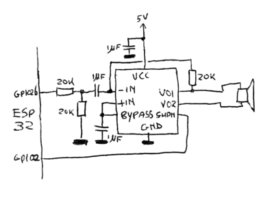
The Macintosh also had sound. By modern standards, its quality is not very high (22 kHz, 8 bits), but the sounds of its programs are now legendary, so I could not refuse them in my project. ESP32 has a built-in 8-bit DAC, which is used to create analog sound waves generated by the emulator. They are then fed to the NS8002, which is a class AB 2-watt audio amplifier mounted in a small SOIC8 format. It is cheap, requires very few supporting components and creates more than enough sound to draw attention to the tiny Mac.
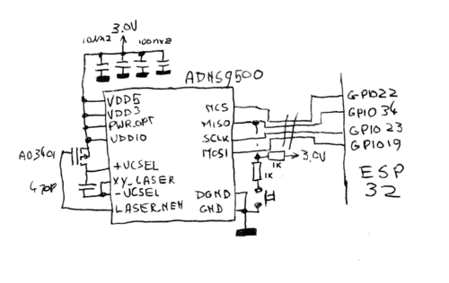
One of the aspects that made the Macintosh so revolutionary was that it became one of the first commercial computers with a mouse. The Macintosh team thought the mouse so carefully that almost the entire OS is based on mouse-driven UI elements, and unlike the IBM PC, for example, the entire Macintosh could be controlled by the mouse. Obviously, my tiny Mac also needed this important peripheral. I still remember the ball mice that were sold with the first Macintosh, but I was not very happy about the need to clean the rollers too often from dirt; it is for this reason that these mechanical devices were completely replaced by optical mice. The advantage of this is that it is quite easy to find the details for these newfangled optical mice: for example, it did not take me long to find out the seller of sensors for gaming mice ADNS9500 and the corresponding optics.
Another convenient aspect is that the optical mouse sensor is a fairly deeply integrated device: it requires only a few external components to work, and this is reflected in the diagram. Added a few capacitors to stabilize the voltage, a MOS transistor (copied directly from the datasheet) to turn on the laser diode and other standard parts. The mouse sensor transmits data through a four-wire SPI signal, and I used one of these wires to send a mouse button signal: when I press the button, the MISO contact pulls down quite strongly. The value of this pull-down resistor is not enough for the mouse to stop transmitting data, but it is sufficient to overcome the pull-up resistor, which normally pulls the bus up, so when the sensor creates three states in the MISO bus, ESP32 can recognize the button is pressed.
Finally, you need to connect an OLED screen. We have already done all the hard work of calculating the values of all resistors, so the circuit should more or less speak for itself. The added chip is a D-trigger, and it is used to halve the clock frequency: as stated above, the MIPI standard requires a new bit each time the polarity of the clock signal is inverted, while ESP32 transmits a new bit only in the front or rear front.
Having drawn a schematic diagram, I went on to create a PCB design. The display I chose was to be mounted on the control board, and the connector should be on the back of this circuit board. Although there would not have been much room for other components, I still wanted to place all the other components on the other side.
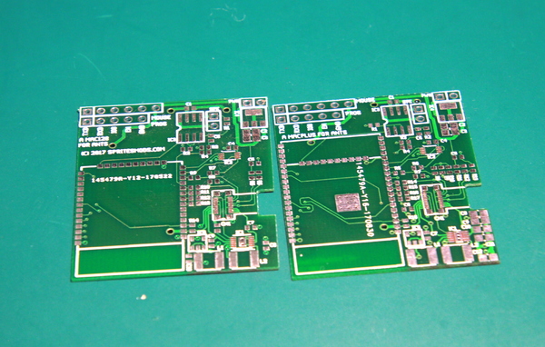
It’s great to have good vision and heat gun: it allowed me to use the components 0603 and arrange everything in the limited space of the board. It would be especially difficult to connect the display connector and the OLED QFN power supply chip with a regular soldering iron.
I realized that the mouse sensor and its components would take up too much space on the board, so I decided to solder all the components to the sensor itself. Thanks to this, everything can be put into the mouse.

Software
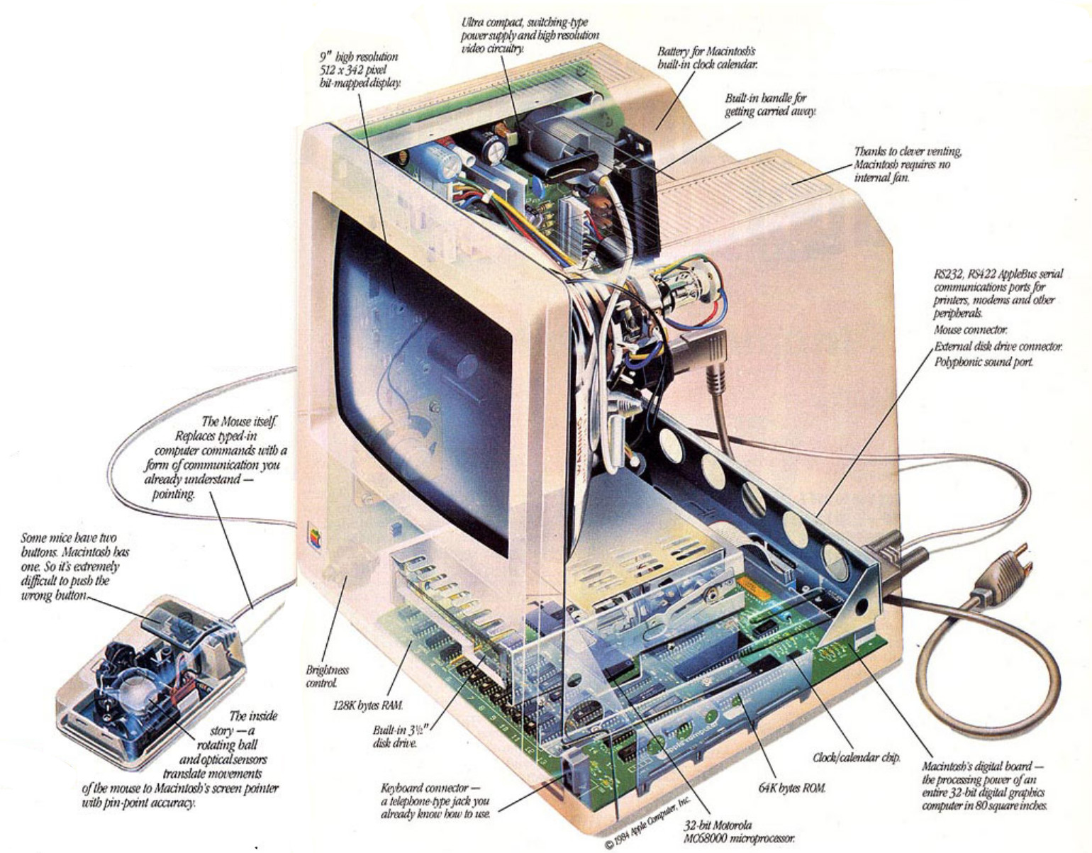
Obviously, a fairly important element of this assembly is software: you must emulate the entire Macintosh. However, Macintosh is not such a complicated machine. In essence, it consists of a 68000 microcontroller, a Zilog Z8530 serial controller, managing a serial port, 6522 VIA for internal I / O and for providing an interface with a keyboard, as well as several programmable logic matrices (PAL) containing logic for display and sound. It also has an Integrated Woz Machine chip, providing an interface with a floppy drive. This is a rather complicated chip; however, I do not plan to emulate a floppy disk, so it will be sufficient to emulate an IWM that constantly returns that there is no disk in the drive. Instead, I plan to fully emulate a NCR 5380 SCSI chip connected to an SCSI emulated hard disk that will read from the flash memory embedded in the ESP32-Wrover module.
Moreover, the system will have very few programs with direct access to hardware: programmers who created software for the Mac were told to use OS-level hardware abstraction layers from the very beginning to maintain compatibility with future versions of Mac hardware. In general, this means that if I manage to emulate hardware to such an extent that the OS boots and is happy with everything, then most of the programs will work without any problems.
So I decided that I could try writing an emulator from scratch. More precisely, not quite from scratch; 68000 is a rather complex beast and I did not want to reinvent this bike. Instead, I searched the Internet and found that MAME has a convenient and fast 68K C-based emulator called Musashi, which is well suited to my requirements. It will be necessary to conjure a bit to transfer opcodes instead of RAM to flash memory, but otherwise, almost nothing is needed to port to ESP32.
However, I did not plan to develop the whole project on ESP32: since the chip has support for OpenOCD, which provides quite extensive debugging capabilities, the “load-test-fix-load-cycle” cycle will be too monotonous. So I decided to first develop everything on my Linux machine, not forgetting the limitations of ESP32. So I got to work, using datasheet for different chips, Linux-68K information for the machine, as well as Inside Macintosh information that can be found on the Internet. When I could not figure out what to do next, you could look under the hood of other open source emulators .
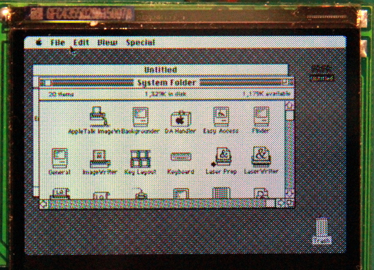
Armed with all of this, choosing gcc as the C compiler and libsdl as the library for working with graphics, I set to work. In short, after a while, I’ll have a simple, but generally functioning MacPlus emulator: mouse, video, SCSI hard disk and sound work:

Since my hardware was not ready yet, I decided to port my emulator to the devboard ESP-Wrover-Kit. I still had several such boards at hand, and besides the Wrover module, which I will already use, they have a handy 320x240 display, which you can use to test the video.

After setting up, the Mac emulator earned quite well on this board; in fact, it's usually pretty close to 7.8 MHz, on which Mac Plus runs. (7.8 MHz will be slightly faster than Mac Plus; since in a real machine, some of the memory cycles eats off the frame buffer and sound system, the frequency can be reduced by 35%.)
Obviously, the work of the emulator on the devboard is a good step forward, but in the end everything should work on the screen I bought, not on the devboard screen. And one more thing: the devkit screen has a 320x240 screen and cuts off a solid part of the Mac screen. The display, which I will use, has a size of 320x320, and therefore more only vertically: how will I manage to display on it a Mac screen of 512x342?
There is only one way to put 512x342 pixels on a 320x320 screen, and that is scaling. In essence, we take an image, compress it, make it smaller, and then display it. However, scaling can be done in a bunch of different ways, and considering that the black and white image generated by the OS assumes that each pixel creates a clearly defined point of light on the screen, that is, there are many ways to spoil everything. I need to lose as few pixel resolution as possible. That is, it is necessary to increase the resolution of the OLED screen.
But how to do that? It is hardly possible to open the OLED-screen and shove some more pixels inside. However, this is not necessary; The resolution of the OLED-display and so is three times more than the declared. The reason is that this screen is colored: each virtual “pixel” has red, green, and blue subpixels. In addition, in this particular screen subpixels are lined up with a triangle. Here is a close screenshot with three pixels turned on:
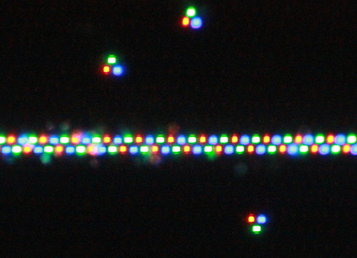
As you can see, pixels are triangular sets of three subpixels; depending on the column, the triangles point down or up. In essence, this means that the subpixel screen resolution is 480 x 640 pixels. Although this is still not enough to display 512x342 pixels, the difference is so small that, with the right choice of small scaling, the display will be as readable as possible for a 1.63-inch screen displaying a GUI designed for a 9-inch screen:
Housing
So, now I have a display and software that emulates Macintosh Plus quite well, plus a microcontroller on which it can be run. What is missing? Obviously, the hull for all this!
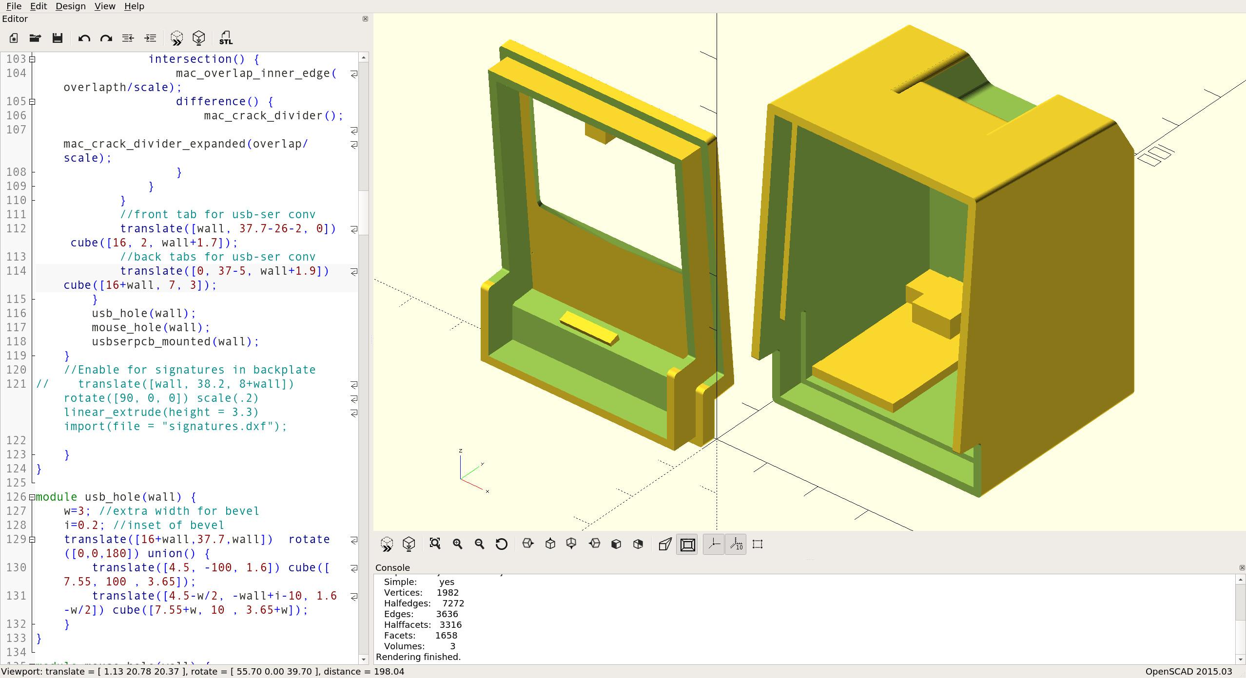
I decided to print it on a Formlabs 1+ SLA 3D printer from my work. For this, I first need a model. I wanted to create it from scratch. Obviously, it’s better to have a real Macintosh Plus at hand. In fact, I have it, but we are separated by a half-continent ... Fortunately, I managed to find almost as good a solution: a kind person indicated the dimensions of the original Mac 128K (the body of which is almost the same as Plus) in the wiki iFixit .
I still create all my 3D models in OpenScad, and after suffering and cursing I managed to make all the curves look the way they should. I got a beautiful Mac model at a scale of 1: 6.
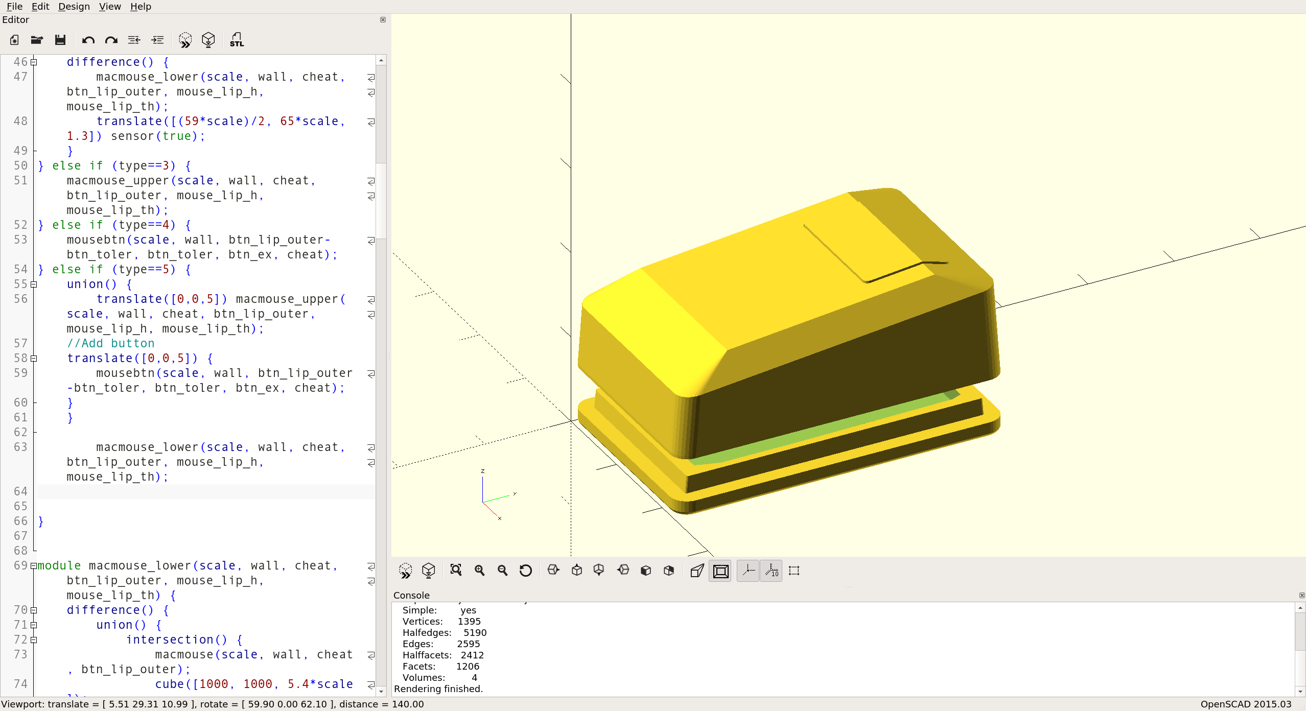
I also created a mouse from images with iFixit, but since a large enough sensor of an optical mouse must fit in it, it cannot be scaled to 1/6 of a real mouse. The scale is closer to 2/5, so the mouse looks big compared to a tiny Mac, but it is much more convenient for unscaled human fingers.
So, all that's left is to print the models. I exported the construct to various STL files and printed them on Formlabs 1+. The end result was quite good; I only regret that I did not add a latch to both parts. This problem was solved by a drop of superglue.

Result
So, I had all the components and it was necessary only to assemble them. PCB connectors in the front of the case are fastened with several clips. The usb-to-serial converter, used as a loading mechanism and power source, is connected to the back and also holds on several terminals. I forgot to do something for mounting inside the speaker, but I managed to fix it in the case with superglue. The mouse is connected by a set of thin wires. (Yes, they somewhat do not correspond to the color scheme ... as soon as I find a more beautiful stranded cable, I will correct it.)
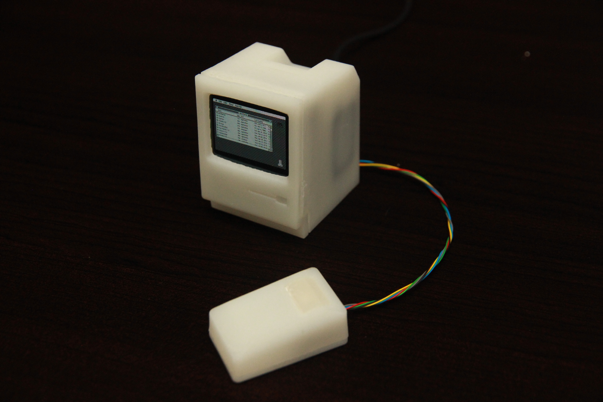
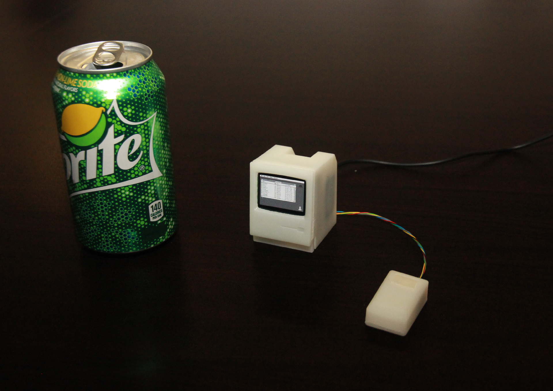
When you design everything on a computer, you realize the true scale of the product only when the project materializes completely, for example, when you receive printed circuit boards from the factory or after you have finished printing a case design on a 3D printer, on which you worked for weeks. Of course, I knew that everything would be six times smaller than the original Mac, but only having gathered everything together and seeing the car live, I realized what it means. Mac really turned out to be tiny!

And even despite the small size and lack of a keyboard, it is able to run most of the programs that the Mac is famous for.Here is a demonstration. The first 20 seconds a memory check is performed, and I know from experience that such a long check is not a bug: the original Mac Plus took the same amount of time to load, even after the upgrade.
So, what's good about this Mac Plus? Although I enjoyed creating it, I must admit that without a keyboard it cannot be used to its full potential. In addition, it does not have the means of communication: I planned to implement AppleTalk via WiFi, but I could not do it because of the oddities that I could not emulate in the chip of the serial bus controller of the original Mac. However, having completed the project in this state, I can finally fulfill my long-cherished dream and put a Mac on the table with Toaster screen savers flying across the screen:

As usual, this project is open-source, the design of the PCB and case, as well as the firmware are laid out on Github . Everything is licensed under the Beer-Ware license, so you can do almost anything you want with it. If you ever use something in your projects, you can write about it to me.
Source: https://habr.com/ru/post/444574/
All Articles