Wolfenstein 3D: ray tracing with WebGL1
After the appearance of Nvidia RTX graphics cards last summer, ray tracing has once again gained its former popularity. Over the past few months, my Twitter feed has filled an endless stream of graphics comparisons with RTX turned on and off.
After admiring such a number of beautiful images, I wanted to independently try to combine the classic forward renderer with the ray tracer.
Suffering from the rejection syndrome of someone else's development , I as a result created my own rendering engine based on WebGL1. You can play with the Wolfenstein 3D level rendering demo with spheres (which I used due to ray tracing) here .
Prototype
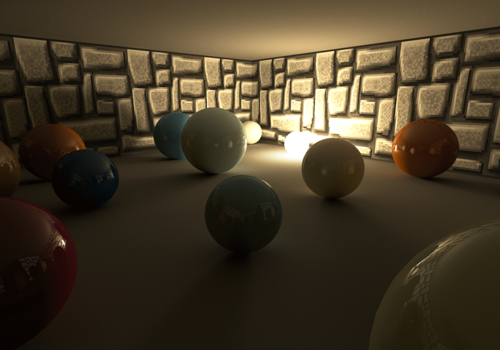
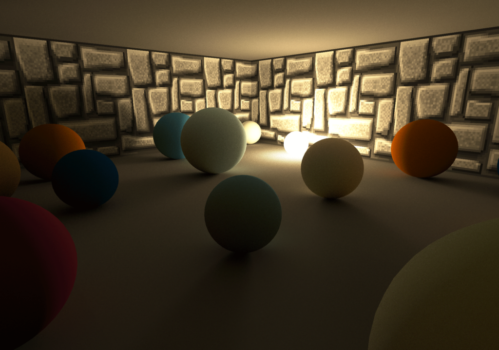
I started this project by creating a prototype, trying to recreate global illumination with ray tracing from Metro Exodus .
')

First prototype showing diffused global illumination (Diffuse GI)
The prototype is based on a forward renderer that renders the entire geometry of the scene. The shader used for rasterization of the geometry not only calculates direct illumination, but also emits random rays from the surface of the rendered geometry for accumulation of indirect rays of reflection from non-shiny surfaces (Diffuse GI) using the tracer.
In the image above you can see how all the spheres are correctly illuminated only by indirect illumination (rays of light are reflected from the wall behind the camera). The light source itself is covered by a brown wall on the left side of the image.
Wolfenstein 3d
The prototype uses a very simple scene. It has only one light source and only a few spheres and cubes are rendered. Because of this, the ray tracing code in the shader is very simple. A rough loop through the intersection check, in which the beam is tested for intersection with all the cubes and spheres in the scene, is still fast enough for the program to perform in real time.
After creating this prototype, I wanted to do something more complicated by adding more geometry and lots of light sources to the scene.
The problem with a more complex environment is that I still need to be able to trace the rays in the scene in real time. Normally, the structure of the bounding volume hierarchy (BVH) would be used to speed up the ray tracing process, but my decision to create this project on WebGL1 did not allow this: WebGL1 cannot load 16-bit data into texture and cannot use binary operations in a shader. This complicates the preliminary calculation and application of BVH in WebGL1 shaders.
That is why I decided to use Wolfenstein 3D for this demo. In 2013, I created a single fragmentary WebGL shader in Shadertoy , which not only renders Wolfenstein-like levels, but also procedurally creates all the necessary textures. From my experience with this shader, I knew that the grid-based construction of Wolfenstein levels can also be used as a fast and simple acceleration structure, and that ray tracing along this structure will be very fast.
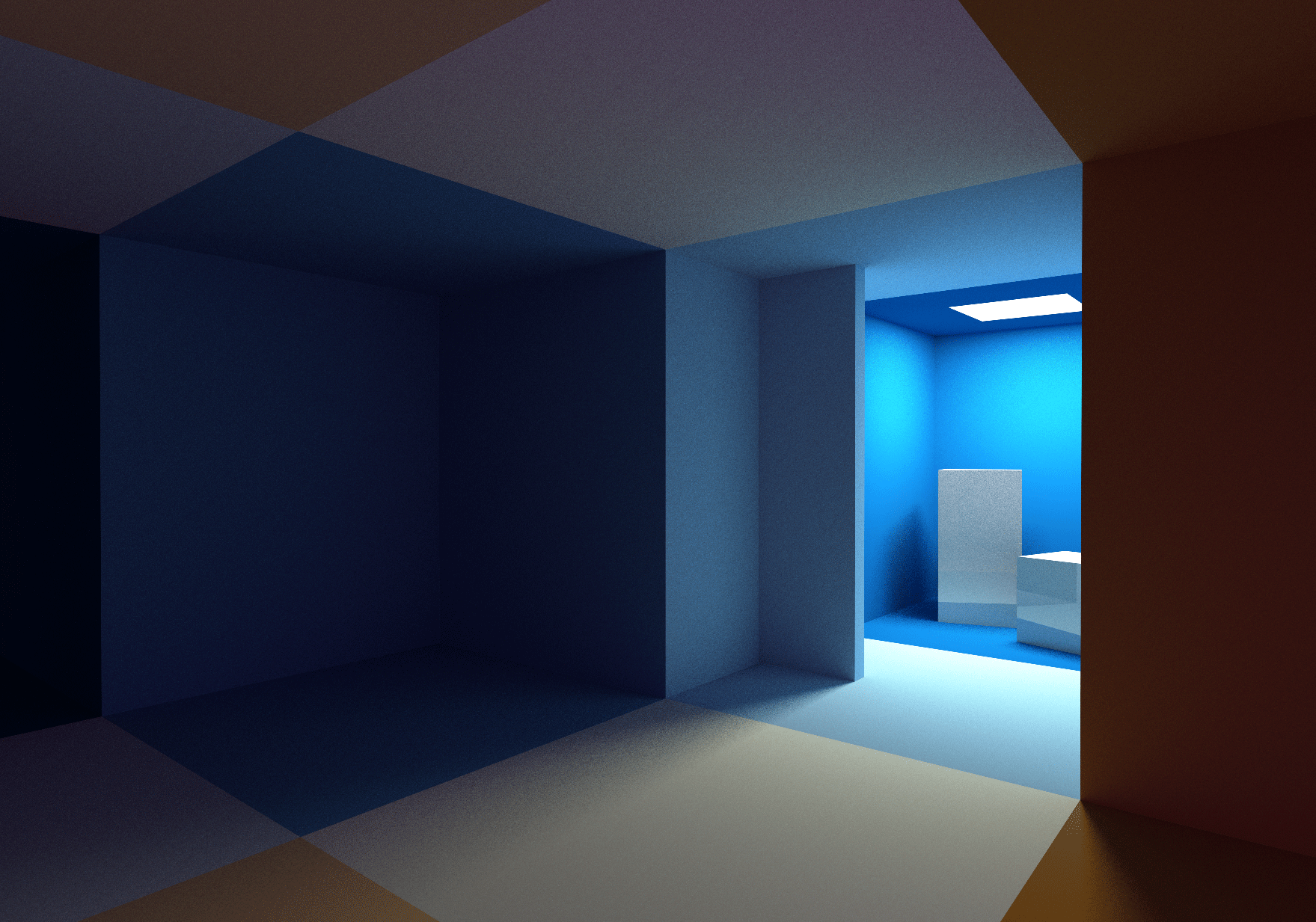
Below is a screenshot of the demo, and in full screen mode you can play it here: https://reindernijhoff.net/wolfrt .
Short description
The demo uses a hybrid rendering engine. To render all polygons in a frame, it uses traditional rasterization, and then combines the result with shadows, diffuse GI and reflections created by ray tracing.

Shadows
Diffuse gi
Reflections
Proactive rendering
Wolfenstein maps can be fully encoded into a 64 × 64 two-dimensional grid. The map used in the demo is based on the first level of Wolfenstein 3D episode 1 .
At launch, all geometry is created that is necessary for the advance rendering rendering. A wall mesh is generated from the map data. There are also floor and ceiling planes, separate meshes for lighting sources, doors and randomly-spaced spheres.
All textures used for walls and doors are packed into a single texture atlas, so all walls can be drawn in one draw call.
Shadows and lighting
Direct illumination is computed in the shader used for the pre-render rendering. Each fragment can be illuminated (maximum) by four different sources. To know which sources can influence the fragment in the shader, when you run the demo, the search texture is precomputed. This search texture is 64 by 128 and encodes the positions of the 4 closest light sources for each position in the map grid.
varying vec3 vWorldPos; varying vec3 vNormal; void main(void) { vec3 ro = vWorldPos; vec3 normal = normalize(vNormal); vec3 light = vec3(0); for (int i=0; i<LIGHTS_ENCODED_IN_MAP; i++) { light += sampleLight(i, ro, normal); } To obtain soft shadows for each fragment and light source, a random position in the light source is sampled. Using the ray-tracing code in the shader (see below, “Ray-tracing”), a shadow beam is emitted to the sampling point to determine the visibility of the light source.
After adding (auxiliary) reflections (see the “Reflection” section below), the diffuse GI is added to the calculated fragment color by performing a search in the Diffuse GI Render Target (see below).
Ray tracing
Although in the prototype the ray-tracing code for the diffuse GI was combined with the pre-emptive shader, I decided to separate them in the demo.
I divided them by performing the second drawing of the whole geometry into a separate render target (Diffuse GI Render Target) using another shader that only emits random rays to collect the diffuse GI (see below the section “Diffuse GI”). The illumination collected in this render target is added to the direct illumination calculated in the aisle of the anticipating render.
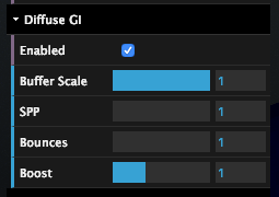
By separating the preemptive pass and diffuse GI, we can emit less than one diffuse GI beam per screen pixel. This can be done by reducing the Buffer Scale (by moving the slider in the parameters in the upper right corner of the screen).
For example, if the Buffer Scale is 0.5, then only one beam will be emitted for every four screen pixels. This gives a huge performance boost. Using the same UI in the upper right corner of the screen, you can also change the number of samples per pixel in the render target (SPP) and the number of reflections of the beam.
Emit beam
To be able to emit rays into the scene, all level geometry must be in a format that the ray tracer can use in the shader. The Wolfenstein level is encoded with a 64 × 64 grid, so it is easy enough to encode all the data into a single 64 × 64 texture:
- In the red channel of the texture, all the objects in the corresponding cell of the x, y grid of the map are encoded. If the value of the red channel is zero, then there are no objects in the cell, otherwise, it is occupied by a wall (values from 1 to 64), a door, a light source or a sphere that need to be checked for intersection.
- If a level grid cell occupies a sphere, then the green, blue and alpha channel are used to encode the radius and relative x and y coordinates of the sphere inside the grid cell.
Emitting a beam in a scene is performed by traversing the texture with the following code:
bool worldHit(n vec3 ro,in vec3 rd,in float t_min, in float t_max, inout vec3 recPos, inout vec3 recNormal, inout vec3 recColor) { vec3 pos = floor(ro); vec3 ri = 1.0/rd; vec3 rs = sign(rd); vec3 dis = (pos-ro + 0.5 + rs*0.5) * ri; for( int i=0; i<MAXSTEPS; i++ ) { vec3 mm = step(dis.xyz, dis.zyx); dis += mm * rs * ri; pos += mm * rs; vec4 mapType = texture2D(_MapTexture, pos.xz * (1. / 64.)); if (isWall(mapType)) { ... return true; } } return false; } A similar mesh tracing code can be found in this Wolfenstein shader on Shadertoy.
After calculating the intersection point with the wall or door (using the intersection parallelogram test ), a search in the same texture atlas that was used to prefetch the rendering gives us the albedo intersection points. Spheres have a color that is procedurally determined based on their x, y coordinates in the grid and the color gradient function .
Everything is a little more difficult with the doors, because they are moving. So that the representation of the scene in the CPU (used to render meshes in the proactive rendering pass) would be the same as the representation of the scene in the GPU (used for ray tracing), all doors move automatically and deterministically based on the distance from the camera to the door.
Diffuse gi
The diffuse global illumination (diffuse GI) is calculated by emitting rays in the shader, which is used to draw all the geometry in the Diffuse GI Render Target. The direction of these rays depends on the normal to the surface, determined by sampling the cosine-weighted hemisphere.
Having the direction of the ray rd and the starting point ro , the reflected light can be calculated using the following cycle:
vec3 getBounceCol(in vec3 ro, in vec3 rd, in vec3 col) { vec3 emitted = vec3(0); vec3 recPos, recNormal, recColor; for (int i=0; i<MAX_RECURSION; i++) { if (worldHit(ro, rd, 0.001, 20., recPos, recNormal, recColor)) { // if (isLightHit) { // direct light sampling code // return vec3(0); // } col *= recColor; for (int i=0; i<2; i++) { emitted += col * sampleLight(i, recPos, recNormal); } } else { return emitted; } rd = cosWeightedRandomHemisphereDirection(recNormal); ro = recPos; } return emitted; } In order to reduce noise, direct light sampling is added to the loop. This is similar to the technique used in my shader Yet another Cornell Box on Shadertoy.
Reflection
Due to the possibility of tracing the scene by rays in a shader, it is very easy to add reflections. In my demo, reflections are added by calling the same getBounceCol method shown above using the reflected camera beam:
#ifdef REFLECTION col = mix(col, getReflectionCol(ro, reflect(normalize(vWorldPos - _CamPos), normal), albedo), .15); #endif Reflections are added in the proactive rendering pass, therefore one reflection ray will always be emitted onto one screen pixel.

Temporal anti-aliasing
As for the soft shadows in the preemptive rendering aisle, and in the diffuse GI approximation, approximately one sample per pixel is used, the end result is extremely noisy. To reduce the amount of noise, temporal anti-aliasing (TAA) is used, implemented on the basis of Playdead's TAA: Temporal Reprojection Anti-Aliasing in INSIDE .
Re-projection
The idea behind TAA is quite simple: TAA calculates one subpixel per frame, and then averages its values with a correlating pixel from the previous frame.
To know where the current pixel was in the previous frame, the fragment position is re-projected using the model-view-projection matrix of the previous frame.
Dropping Samples and Neighborhood Restriction
In some cases, the sample saved from the past is invalid, for example, when the camera has moved in such a way that the fragment of the current frame in the previous frame was closed by the geometry. To discard such invalid samples, a neighborhood constraint is used. I chose the most simple type of restriction:
vec3 history = texture2D(_History, uvOld ).rgb; for (float x = -1.; x <= 1.; x+=1.) { for (float y = -1.; y <= 1.; y+=1.) { vec3 n = texture2D(_New, vUV + vec2(x,y) / _Resolution).rgb; mx = max(n, mx); mn = min(n, mn); } } vec3 history_clamped = clamp(history, mn, mx); I also tried to use the constraint method based on the bounding parallelogram, but I didn’t see much difference with my decision. It probably happened because there are many identical dark colors in the scene from the demo and there are almost no moving objects.
Camera shake
To obtain anti-aliasing, the camera in each frame oscillates due to the use of (pseudo) random sub-pixel offset. This is implemented by changing the projection matrix:
this._projectionMatrix[2 * 4 + 0] += (this.getHaltonSequence(frame % 51, 2) - .5) / renderWidth; this._projectionMatrix[2 * 4 + 1] += (this.getHaltonSequence(frame % 41, 3) - .5) / renderHeight; Noise
Noise is the basis of the algorithms used to calculate diffuse GI and soft shadows. Using good noise greatly affects image quality, while poor noise creates artifacts or slows down the convergence of images.
I'm afraid that the white noise used in this demo is not very good.
Probably the use of good noise is the most important aspect of improving the quality of the image in this demo. For example, you can use blue noise .
I conducted experiments with noise based on the golden section, but they were not crowned with particular success. For now, Dave Hoskins' reputed Hash without Sine is used :
vec2 hash2() { vec3 p3 = fract(vec3(g_seed += 0.1) * HASHSCALE3); p3 += dot(p3, p3.yzx + 19.19); return fract((p3.xx+p3.yz)*p3.zy); } 
Noise reduction
Even with TAA enabled, a lot of noise is still visible in the demo. It is especially difficult to render the ceiling, because it is illuminated only by indirect lighting. It does not simplify the situation and the fact that the ceiling is a large flat surface filled with solid color: if it had a texture or geometric details, the noise would have become less noticeable.
I didn’t want to spend a lot of time on this part of the demo, so I tried to apply only one noise reduction filter: Median3x3 Morgan McGuire and Kyle Whitson . Unfortunately, this filter does not work well with “pixel art” graphics of wall textures: it removes all the details away and rounds the corners of the pixels of nearby walls.
In another experiment, I applied the same filter to the Diffuse GI Render Target. Although he lowered the noise a little, at the same time almost without changing the details of the wall textures, I decided that this improvement was not worth the extra milliseconds spent.
Demo
The demo can be played here .
Source: https://habr.com/ru/post/444516/
All Articles