Resuscitation Tester Marcus
Santa Claus put me under a Christmas tree tester of electronic components in the form of a Chinese clone of the widely known tester Marcus in narrow circles.

There should have been a picture of the included tester with the screen gleefully glowing with all the colors of the rainbow, but the hands from one place stuck a charged capacitor into it, the tester happily switched itself off, said “oh!” And refused to work.
Sorry, damn it. Let's try to repair.
1. Go to the Yandex disk with diagrams and firmware for all clones known to the community . Fortunately, clone "TS-1" is already there.
')
2. We study the circuit and the tester board, experimentally finding out that there is a short circuit (short circuit) on the + 5V bus.
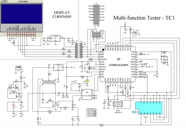
If the tester is self-powered when a capacitor is connected, then the power is applied to the bus either through the built-in reverse diodes at the inputs of the microcontroller or through the protective assembly DZ2.
We unsolder the DZ2, the assembly is alive, the short circuit is in place. So the most terrible thing happened, the microcontroller burned down.
3. Order the Atmega644 microcontroller, TQFP-44 package, 2 pieces, in case something goes wrong.
4. While Atmega is traveling from China, we are preparing the tools and are looking for a programmer.
We will need:

4.1. Soldering station, a set of tips for a soldering iron, a "third hand" with a magnifying glass, thin-thin tweezers, a good flux (Chinese, but liquid, which is better than rosin), a little bit of solder.
Programmers (thanks to Int_13h for donating the whole box of all sorts of different things ):
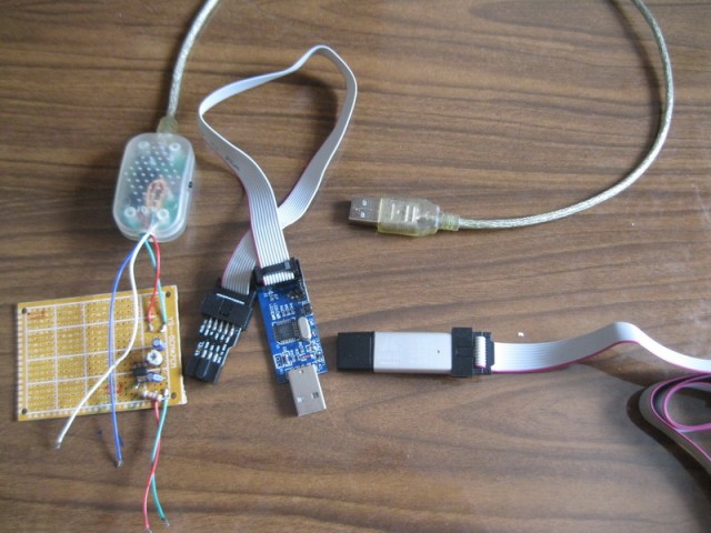
4.2. USBasp without case for Atmega, with an adapter 10 pin to 6 pin ISP.
4.3. USB ISP in the case for Atmega (never guess which one is useful).
4.4. USB / UART 5V converter from a mobile phone for flashing the U4 power controller (STC15L104W).
Since controller loves 3.3V; on the montage we assemble the stabilizer 5-> 3.3V on the basis of LM1117:
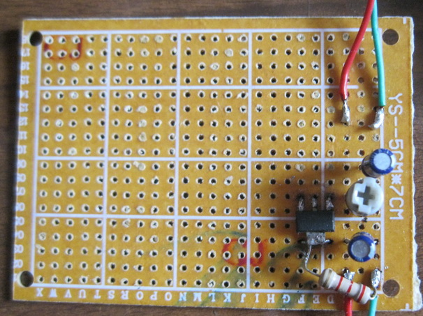
It turns out that the stabilizer without load does not work. We hang on the output of a resistor, for example, 2.2 kΩ. We install at the output exactly 3.3 V with a voltmeter and a potentiometer.
5. We finally got an envelope with microcontrollers.
6. Disassemble the burned-out microcontroller with a hair dryer, clean the pads, lubricate with flux, solder a new one. Thin sting, each leg. But first in the corners. They say you can and hairdryer, but there is no solder paste.

For the first time, even pretty.
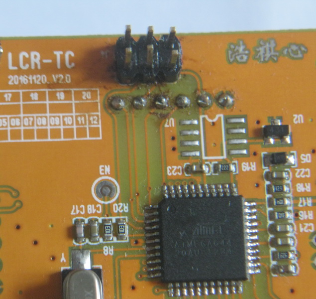
At the same time solder the connector for in-circuit programming. Make sure the wiring for the 10to6 adapter is correct, and solder the connector to the other side of the board.
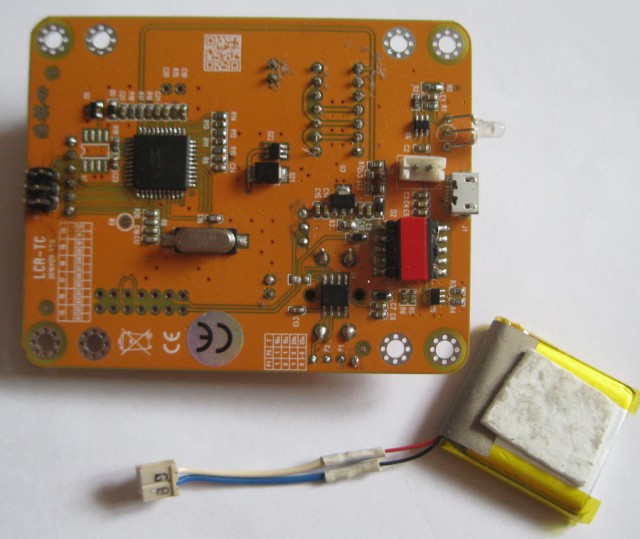
And of course we will provide a battery connector. Total:
7. Getting ready to flash the U4 power controller. Solder a USB-UART converter with a stabilizer to the board:
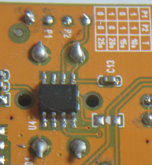
3.3V to 3.3V, Gnd to Gnd, Tx to P1, Rx to P2.
8. We are looking for software stc-isp6.86.rar on the manufacturer's website .
9. Connect the converter, wait for it to be detected by the system, start the software, select the com-port, select the firmware from the archive (item 1), set the frequency to 12 MHz, power on, the processor starts, does not go into boot mode, the programmer is not detected .
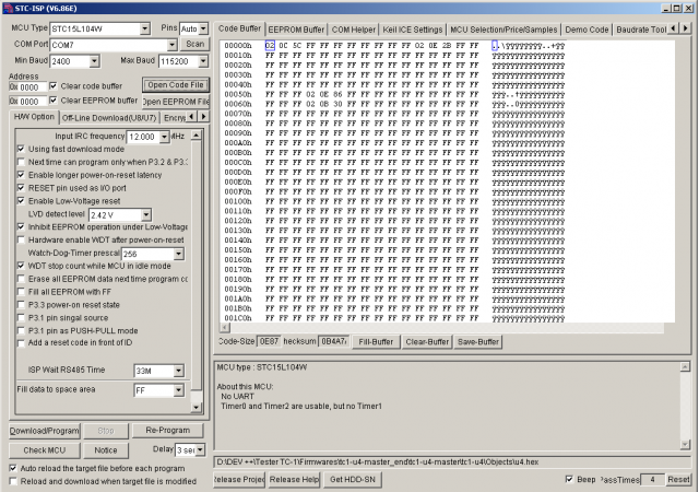
9.1. We experiment with the order of power supply to the processor and pressing the buttons "Check MCU" & "Download / Program".
9.2. We study the datasheet on U4, we find that the Test button of the tester is connected to the Reset pin. We press "Check MCU", we press the Test button, the microcontroller resets and is detected. In the same way, run the firmware, and finally flash U4.
10. We study the abundance of software for Atmega firmware.
10.1. We install the powerful and convenient Atmel Studio 6.2, we find out that it does not support USBasp and USB ISP programmers. Demolish
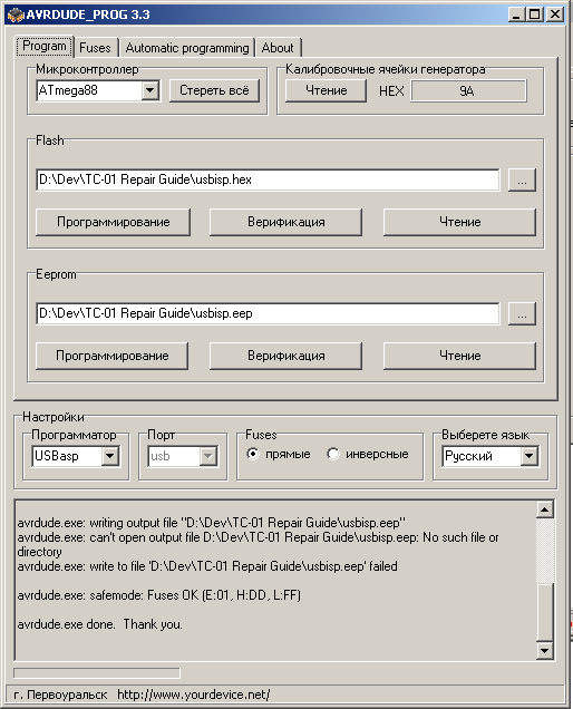
10.2. We are looking for Avrdude and a graphical shell to it. Of all the abundance, we stop at the intuitive Avrdude_prog 3.3, which understands USBasp, understands * .hex and * .eep firmware, and is able to visually display selected fyuzy. Connect, run:
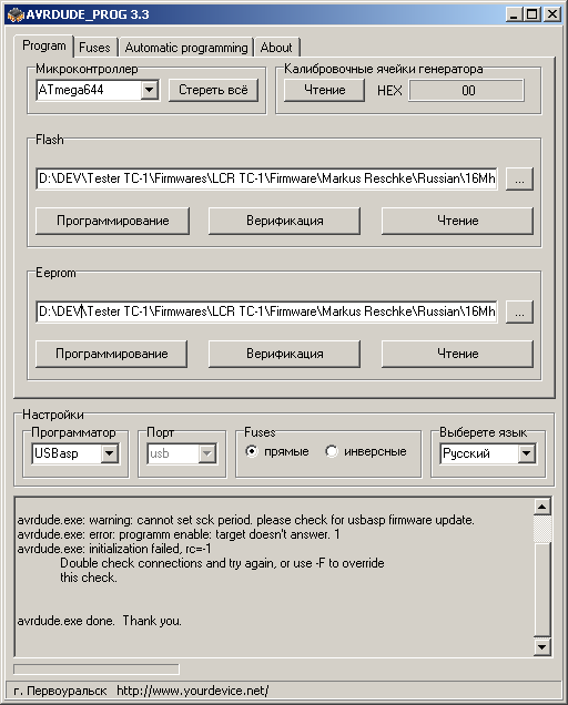
Bummer-s, the programmer has too old firmware.
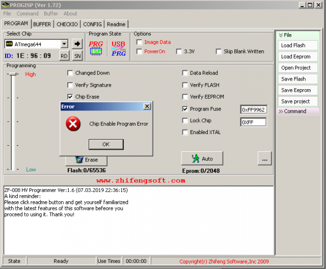
10.3. This is where USB ISP comes in handy, the software of which is not so friendly, but it is capable of inserting a programmer’s firmware. And maybe the tester will flash it? Alas:
10.4. We are looking for a new firmware on USBasp, we connect USB ISP and USBasp with a loop, we close jumper J1 to USBasp, entering it into programming mode. Fill the firmware. Success!
10.5. Inspired with success, we are trying to flash USB ISP in USBasp. Solder the jumper to the board by the method, first back up the firmware and fuses.

10.6. We sew.

Solder jumper. We connect the former USB ISP and computer and do not detect it with software. Can confuse with fyuzami? Then we'll figure it out. Sorry! But you have fulfilled your goal and you can rest in peace for the time being.
10.7. Goto 10.2. But now our programmer is already sewing Atmega successfully.
11. We worry about the success of the operation.
12. Run the tester. Bingo!
Measurements are underway, but there were some drawbacks as well - the tester almost instantly turns off after the measurement process, and you can’t have time to take readings.
In the next series: attempts to make your firmware for the tester to eliminate the effect of instantaneous disconnection. The firmware will be based on the source code of Marcus . And also, as I tried, but could not love the AVR.
There should have been a picture of the included tester with the screen gleefully glowing with all the colors of the rainbow, but the hands from one place stuck a charged capacitor into it, the tester happily switched itself off, said “oh!” And refused to work.
Sorry, damn it. Let's try to repair.
1. Go to the Yandex disk with diagrams and firmware for all clones known to the community . Fortunately, clone "TS-1" is already there.
')
2. We study the circuit and the tester board, experimentally finding out that there is a short circuit (short circuit) on the + 5V bus.
If the tester is self-powered when a capacitor is connected, then the power is applied to the bus either through the built-in reverse diodes at the inputs of the microcontroller or through the protective assembly DZ2.
We unsolder the DZ2, the assembly is alive, the short circuit is in place. So the most terrible thing happened, the microcontroller burned down.
3. Order the Atmega644 microcontroller, TQFP-44 package, 2 pieces, in case something goes wrong.
4. While Atmega is traveling from China, we are preparing the tools and are looking for a programmer.
We will need:
4.1. Soldering station, a set of tips for a soldering iron, a "third hand" with a magnifying glass, thin-thin tweezers, a good flux (Chinese, but liquid, which is better than rosin), a little bit of solder.
Programmers (thanks to Int_13h for donating the whole box of all sorts of different things ):
4.2. USBasp without case for Atmega, with an adapter 10 pin to 6 pin ISP.
4.3. USB ISP in the case for Atmega (never guess which one is useful).
4.4. USB / UART 5V converter from a mobile phone for flashing the U4 power controller (STC15L104W).
Since controller loves 3.3V; on the montage we assemble the stabilizer 5-> 3.3V on the basis of LM1117:
It turns out that the stabilizer without load does not work. We hang on the output of a resistor, for example, 2.2 kΩ. We install at the output exactly 3.3 V with a voltmeter and a potentiometer.
5. We finally got an envelope with microcontrollers.
6. Disassemble the burned-out microcontroller with a hair dryer, clean the pads, lubricate with flux, solder a new one. Thin sting, each leg. But first in the corners. They say you can and hairdryer, but there is no solder paste.
For the first time, even pretty.
At the same time solder the connector for in-circuit programming. Make sure the wiring for the 10to6 adapter is correct, and solder the connector to the other side of the board.
And of course we will provide a battery connector. Total:
7. Getting ready to flash the U4 power controller. Solder a USB-UART converter with a stabilizer to the board:
3.3V to 3.3V, Gnd to Gnd, Tx to P1, Rx to P2.
8. We are looking for software stc-isp6.86.rar on the manufacturer's website .
9. Connect the converter, wait for it to be detected by the system, start the software, select the com-port, select the firmware from the archive (item 1), set the frequency to 12 MHz, power on, the processor starts, does not go into boot mode, the programmer is not detected .
9.1. We experiment with the order of power supply to the processor and pressing the buttons "Check MCU" & "Download / Program".
9.2. We study the datasheet on U4, we find that the Test button of the tester is connected to the Reset pin. We press "Check MCU", we press the Test button, the microcontroller resets and is detected. In the same way, run the firmware, and finally flash U4.
10. We study the abundance of software for Atmega firmware.
10.1. We install the powerful and convenient Atmel Studio 6.2, we find out that it does not support USBasp and USB ISP programmers. Demolish
10.2. We are looking for Avrdude and a graphical shell to it. Of all the abundance, we stop at the intuitive Avrdude_prog 3.3, which understands USBasp, understands * .hex and * .eep firmware, and is able to visually display selected fyuzy. Connect, run:
Bummer-s, the programmer has too old firmware.
10.3. This is where USB ISP comes in handy, the software of which is not so friendly, but it is capable of inserting a programmer’s firmware. And maybe the tester will flash it? Alas:
10.4. We are looking for a new firmware on USBasp, we connect USB ISP and USBasp with a loop, we close jumper J1 to USBasp, entering it into programming mode. Fill the firmware. Success!
10.5. Inspired with success, we are trying to flash USB ISP in USBasp. Solder the jumper to the board by the method, first back up the firmware and fuses.
10.6. We sew.
Solder jumper. We connect the former USB ISP and computer and do not detect it with software. Can confuse with fyuzami? Then we'll figure it out. Sorry! But you have fulfilled your goal and you can rest in peace for the time being.
10.7. Goto 10.2. But now our programmer is already sewing Atmega successfully.
11. We worry about the success of the operation.
12. Run the tester. Bingo!
Measurements are underway, but there were some drawbacks as well - the tester almost instantly turns off after the measurement process, and you can’t have time to take readings.
In the next series: attempts to make your firmware for the tester to eliminate the effect of instantaneous disconnection. The firmware will be based on the source code of Marcus . And also, as I tried, but could not love the AVR.
Source: https://habr.com/ru/post/444152/
All Articles