Easel for microcontroller programmer
Good day. In this short article I want to talk about how the idea came to my mind to make a large mock-up board and how I implemented this idea. It all started ... Yes, in general, it does not matter. The essence of the idea is this: to make a very large breadboard on the basis of bread boards. It turned out like this:
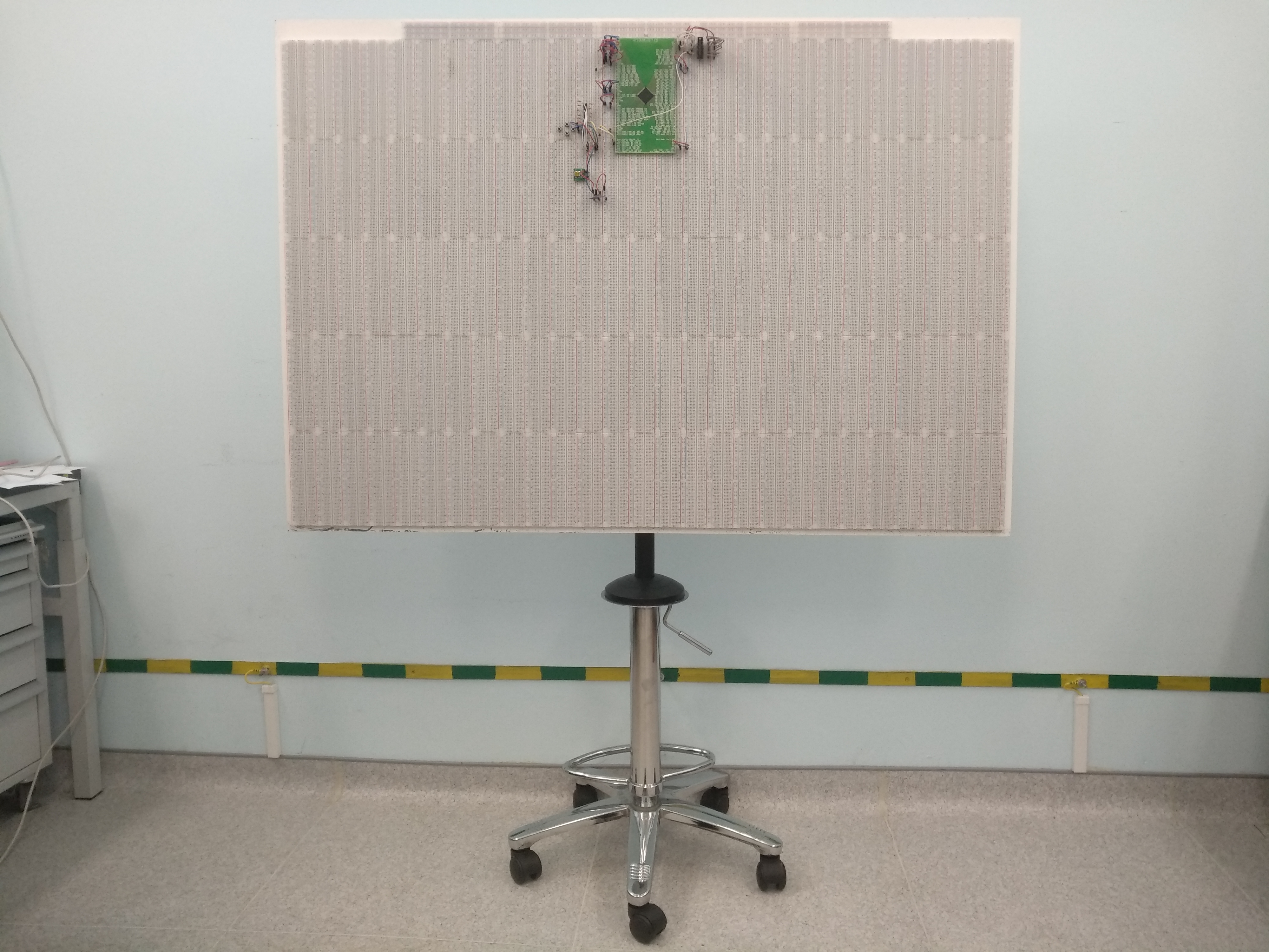
The whole structure consists of the following elements:
The crosspiece, gas lift, support and wheels purchased in the furniture online store. Plywood and paint purchased in Leroy Merlin. The plywood was cut to the right size in the store, very high quality and smooth, otherwise I would have to tinker. The assembly process is, in principle, fairly obvious, although, unfortunately, I did not fix it in the photo or video.
')
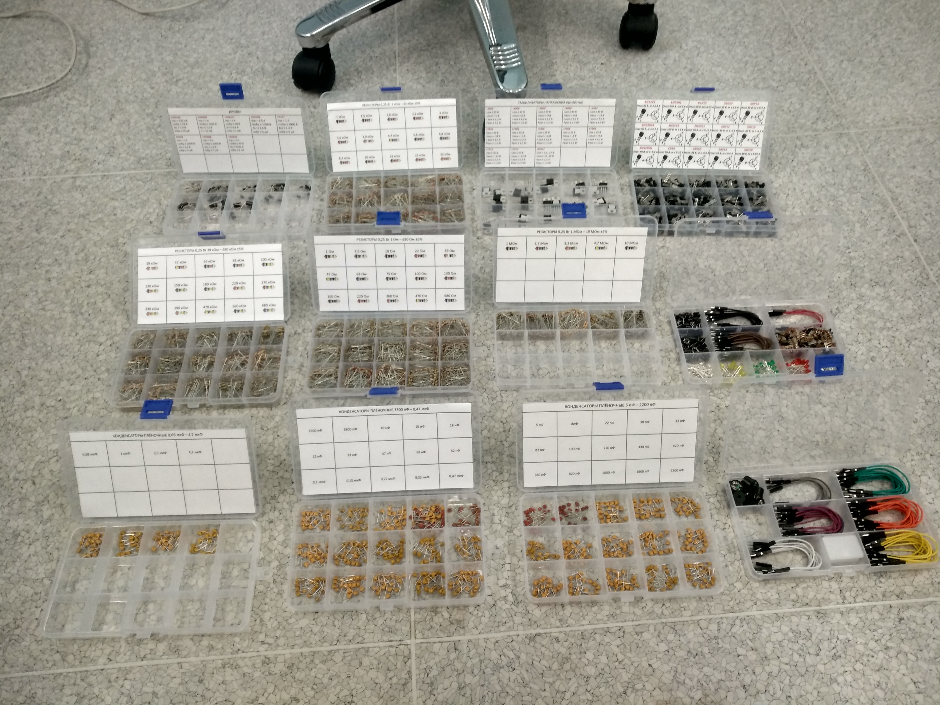
The selection of components for the mock-up took considerable time, and the acquisition cost a pretty penny. The most expensive cost motherboard. There are about 120 of them on the board, I don’t remember exactly, their total cost was about 20 thousand rubles. All the other components pulled another thousand by 15. Plus, the work took some time, which was spent on the design, purchase, processing and assembly. But in general, I am satisfied.
Over time, I got some radio components for prototyping. But, actually, they:
As for work, I have to deal with microcontrollers produced by the PLC Milandr JSC , first of all I ordered a transition board for the K1986BE1QI microcontroller, which I often use during the debugging phase. The transfer board is now inserted into the mock-up board, and it is too lazy to take it out for me, therefore I enclose a photo of the assembled circuit. In the center of the photo is a transition board with a microcontroller. In the upper right corner there is a connector for programming via JTAG, in the lower left there is a power supply circuit that reduces the input voltage of 5V from the USB connector to the nominal supply voltage of the microcontroller, i.e. up to 3.3 V.

This microcontroller has a full-fledged Ethernet, that is, MAC and PHY sublevels, and using several resistors and capacitors, you can solder the RJ-45 connector to the microcontroller pins and connect it to the local network or PC Ethernet port. And I have a set of very well-thought-out software solutions, with the help of which you can set up extensive telemetry between PC and MK via Ethernet. I will write about these solutions in a separate article. As well as the fact that to connect to a LAN microcontroller requires software implementation of the TCP / IP protocol stack. So for now, let's go back to the mockup. I did a transition board trace using the Lite version of Topor, because it is free, and I didn’t want to buy a fully functional version because of one board. And although I rested on the limit on the number of lines (in the free version, it seems, no more than 100 lines, and I have 144 lines on the board, on the number of conclusions of the microcontroller), we managed to circumvent the restriction by distributing only the left side of the board and then getting the trace on the right parts using copy and flip left.
In addition, a whole range of adapters for different connectors were manufactured or purchased, primarily, of course, for the JTAG connector. I supply power to the board via an adapter of a USB-connector, for example, from a USB-connector of a laptop, from charging from a cellular or from a power bank.

As a result, instead of drawing a scheme in CAD, tracing, ordering a prototype and subsequent tests, I begin work with making a layout. Just insert components into the board, connect them with jumpers. After the layout is ready, I feed it. As a rule, I have some basic firmware with the initialization of the IC and the organization of the exchange over the network. I am starting to increase this firmware until the mockup is brought to readiness for testing for operation. As a rule, this approach saves time, and the time saved is spent on the education and development of other tools. Since I’m not the only one working, and my job is to develop a microcontroller connection scheme and writing software, after debugging circuit solutions, I transfer the results to my colleagues, and I’m developing the firmware. Since the manufacture of a prototype in a short time is a rather stressful task, having a working layout is a good help in the work.
That's all, thank you for your attention :)
PS: Since I am a passionate person, if you have an interesting project (i.e., not just blinking the LEDs and kicking up your feet, for example, making a sound reproducing device, connecting a display, and so on), You can try to design it on the board. In this case, you get the means for prototyping, and I get some variety in my developer’s life :) Maybe I’ll give you some advice, maybe I’ll learn something. Although the offer is limited - I have a rather busy schedule ...
The whole structure consists of the following elements:
- Cross and wheels from the office chair.
- Gas lift from the bar stool.
- Reliance from a bar stool.
- Ceiling TV bracket.
- Painted plywood sheet.
- Development Boards.
The crosspiece, gas lift, support and wheels purchased in the furniture online store. Plywood and paint purchased in Leroy Merlin. The plywood was cut to the right size in the store, very high quality and smooth, otherwise I would have to tinker. The assembly process is, in principle, fairly obvious, although, unfortunately, I did not fix it in the photo or video.
')
The selection of components for the mock-up took considerable time, and the acquisition cost a pretty penny. The most expensive cost motherboard. There are about 120 of them on the board, I don’t remember exactly, their total cost was about 20 thousand rubles. All the other components pulled another thousand by 15. Plus, the work took some time, which was spent on the design, purchase, processing and assembly. But in general, I am satisfied.
Over time, I got some radio components for prototyping. But, actually, they:
As for work, I have to deal with microcontrollers produced by the PLC Milandr JSC , first of all I ordered a transition board for the K1986BE1QI microcontroller, which I often use during the debugging phase. The transfer board is now inserted into the mock-up board, and it is too lazy to take it out for me, therefore I enclose a photo of the assembled circuit. In the center of the photo is a transition board with a microcontroller. In the upper right corner there is a connector for programming via JTAG, in the lower left there is a power supply circuit that reduces the input voltage of 5V from the USB connector to the nominal supply voltage of the microcontroller, i.e. up to 3.3 V.
This microcontroller has a full-fledged Ethernet, that is, MAC and PHY sublevels, and using several resistors and capacitors, you can solder the RJ-45 connector to the microcontroller pins and connect it to the local network or PC Ethernet port. And I have a set of very well-thought-out software solutions, with the help of which you can set up extensive telemetry between PC and MK via Ethernet. I will write about these solutions in a separate article. As well as the fact that to connect to a LAN microcontroller requires software implementation of the TCP / IP protocol stack. So for now, let's go back to the mockup. I did a transition board trace using the Lite version of Topor, because it is free, and I didn’t want to buy a fully functional version because of one board. And although I rested on the limit on the number of lines (in the free version, it seems, no more than 100 lines, and I have 144 lines on the board, on the number of conclusions of the microcontroller), we managed to circumvent the restriction by distributing only the left side of the board and then getting the trace on the right parts using copy and flip left.
In addition, a whole range of adapters for different connectors were manufactured or purchased, primarily, of course, for the JTAG connector. I supply power to the board via an adapter of a USB-connector, for example, from a USB-connector of a laptop, from charging from a cellular or from a power bank.
As a result, instead of drawing a scheme in CAD, tracing, ordering a prototype and subsequent tests, I begin work with making a layout. Just insert components into the board, connect them with jumpers. After the layout is ready, I feed it. As a rule, I have some basic firmware with the initialization of the IC and the organization of the exchange over the network. I am starting to increase this firmware until the mockup is brought to readiness for testing for operation. As a rule, this approach saves time, and the time saved is spent on the education and development of other tools. Since I’m not the only one working, and my job is to develop a microcontroller connection scheme and writing software, after debugging circuit solutions, I transfer the results to my colleagues, and I’m developing the firmware. Since the manufacture of a prototype in a short time is a rather stressful task, having a working layout is a good help in the work.
That's all, thank you for your attention :)
PS: Since I am a passionate person, if you have an interesting project (i.e., not just blinking the LEDs and kicking up your feet, for example, making a sound reproducing device, connecting a display, and so on), You can try to design it on the board. In this case, you get the means for prototyping, and I get some variety in my developer’s life :) Maybe I’ll give you some advice, maybe I’ll learn something. Although the offer is limited - I have a rather busy schedule ...
Source: https://habr.com/ru/post/444106/
All Articles