Retro game console do it yourself
This post is an introduction to my project of a "self-made" console video set-up made from scratch. I was inspired by both retro consoles and modern designs, but I had my own architecture. My friends constantly told me that I should tell about my project, and not do everything exclusively “for myself,” so I publish this post.
Attention, this is a translation
How it all began
My name is Sergio Vieira (Sérgio Vieira) I grew up in Portugal in the 80s and 90s, I have a long time nostalgia for retro gaming, especially for third and fourth generation consoles.
A few years ago, I decided to get a better look at electronics and try to make my own console.
I am a programmer by profession and have not had any experience as an electronics engineer, except for (and should not be considered) independent upgrades of my destkop.
Although I didn’t have experience, I said to myself “why not?” I bought several books, several sets of electronics and began to study based on my feelings about what exactly is worth studying.
I wanted to make a console similar to those that make me feel nostalgic, I wanted something between NES and Super Nintendo , or maybe between Sega Master System and Mega Drive .
These consoles had a CPU, an original video chip (at that time they weren't called GPUs yet) and an audio chip, sometimes built-in, and sometimes external.
The games were distributed on cartridges, which in general were extensions of iron, sometimes just ROM chips, and sometimes had additional components.
The original plan was to make a prefix with the following characteristics:
- Without emulation, games and programs should work on real hardware, not necessarily the same from those times, but fast enough for the task, and nothing more.
- With a real retro CPU.
- With analog TV output.
- With sound
- With support for two controllers
- Back scrolling and sprite animation
- With features to support platform games like Mario, and of course all sorts of other games.
- With the download of games and programs from SD cards.
Why SD cards, and not cartridges, well, basically just so much more practical, you can copy them from a computer. And cartridges would mean, firstly, more iron in the console, and secondly, to produce iron for each program.
Production
Video signal
The first thing I do is generate a video signal.
Any console from the period I took as the model had different proprietary graphics chips, which means they all had different specifications.
For this reason, I didn’t want to use a ready-made graphics chip, I also wanted my console to have unique graphics specifications. And since I could not make my own graphics chip, and at that time I could not use FPGA, I decided to limit myself to software generation of a graphic signal using an 8-bit, 20 MHz microcontroller.
This is not overkill, and just enough powerful solution for graphics of the level that was interesting to me.
And so, I started using the Atmega644 microcontroller on a clean 20 MHz to generate a PAL video signal for the TV. I had to beat the PAL protocol, since the chip itself does not know how to do it.

The microcontroller produces an 8-bit color (RGB332, 3 bits red, 3 bits green and 2 blue) and a passive DAC converts it all to RGB. Fortunately, in Portugal, almost all TVs are equipped with a SCART connector and they support RGB input.
The right graphics subsystem
Since the microcontroller is quite powerful, and I decided to use it exclusively for generating the video signal (I called it the VPU - Video Processing Unit), I decided to organize a double-buffer at the same time.
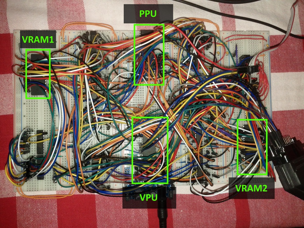
It turned out that the second microcontroller (PPU, Picture Processing Unit, Atmega1284 chip is also 20 MHz) generated a picture in RAM chip number 1 (I called it VRAM1), and the first one at the same time sent the contents of the second chip (VRAM2) to the TV.
After one frame, and two frames in the PAL system are 1/25 seconds, VPU switches VRAMs and they change places, PPU generates a picture in VRAM2, and VPU dumps VRAM1 to a TV output.
The video card was very complicated because I had to use external hardware so that both microcontrollers could use both memory modules and to speed up access to RAM, because there is also bit-banging, so I had to add 74 series chips as counters, line selectors, transceivers, etc. .
Firmware for VPU and PPU also turned out cumbersome because I had to write a lot of code to get the maximum speed out of the graphics. At first everything was written in assembler, then a part was rewritten in C.
As a result, PPU generates a 224x192 pixel image, which is then sent to TV via VPU. The resolution may seem low to you, but actually it is almost as much as the console of that time actually had, usually 256x224. Somewhat lower resolution allowed me to add more features that the system manages to calculate per frame.
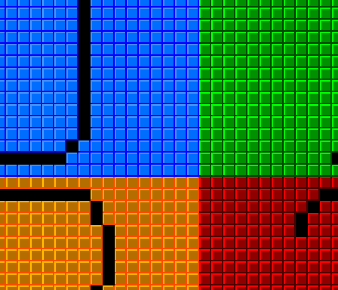
As in the old days, PPU has its own hard mechanics which must be able to use. The substrate (backing) is rendered from 8x8 pixel characters, also called tiles. It turns out that the size of the background is 28x24 tiles.
So that the backside can be scrolled smoothly, pixel by pixel, I made it so that there are 4 virtual screens each, each with 28x24 tiles that go in memory sequentially and wrapped around each other, in the picture it is clearer.

On top of the background, PPU can render 64 sprites that can be 8 or 16 pixels in height or width, that is, 1, 2 or 4 tiles and can still be flip horizontally and / or vertically.
On top of the backup, you can still render an overlay of one 28x6 tile buffer, this was intended to draw HUDs, speeds so as not to interfere with the main sprites and scrolling backups.
One "advanced" feature is that the back can be scrolled not entirely, but each line separately, which allows all sorts of interesting effects like split screen or near- parallax .
There is also an attribute table that allows you to set a value from 0 to 3 for each tile, and then all tiles with one attribute can be set to a page of tiles or to increment their symbolic value. This is convenient when there are parts of the back-up that need to be changed regularly and the CPU does not have to cheat each tile individually; all you need to do is say something like: "all tiles with an attribute 1 increment the numeric value of your character by 2", such things implemented by different technicians can Observe, for example, in block tiles in Mario where the question mark is animated or in games where there is a waterfall in which all tiles are constantly changing creating the effect of falling water.
CPU
When my video card was working, I started working with the CPU as which Zilog 80 was chosen for my console.
One of the reasons why the Z80 was chosen, well, besides the fact that it is a cool retro CPU, is its ability to address two 16-bit spaces, one for memory and one for input / output ports, the equally legendary 6502 , for example, cannot , it can only address one 16-bit space, and it is necessary to load both memory and various external devices, video, audio, joysticks, hardware random number generator, etc. into it. It is more convenient to have two address spaces, one completely given to 64 kilobytes of code and data in memory and the second to access external devices.
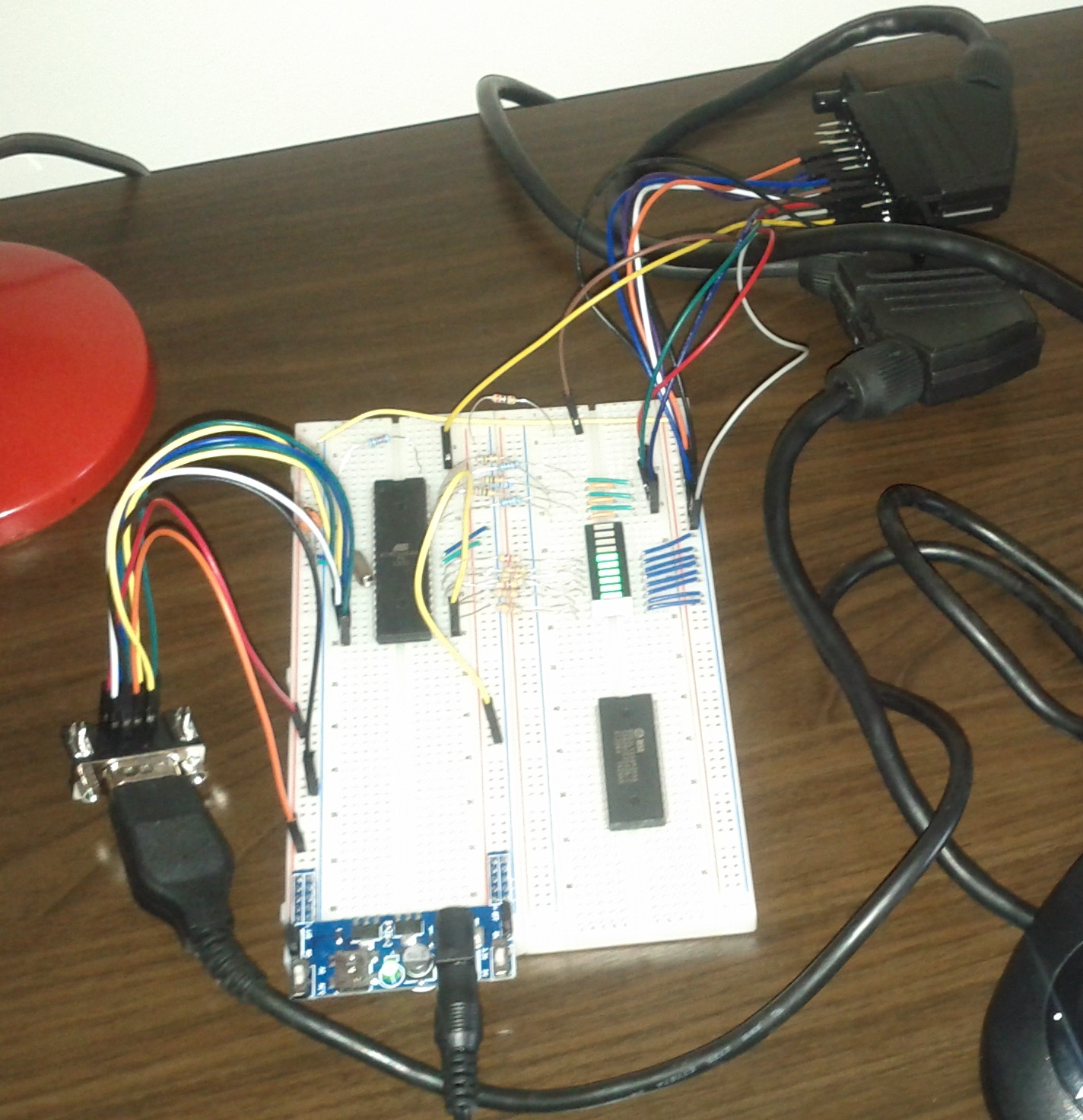
First, I connected the CPU to the EEPROM in which my test program was located and connected it via I / O space to the microcontroller that I installed so that you can communicate with my computer via RS232 , and monitor how the CPU works and everything else. This Atmega324 microcontroller operating at 20 MHz I call the IO MCU - the input / output microcontroller unit, it is responsible for controlling access to the game controllers (joysticks), the SD card reader, the PS / 2 keyboard and the communicator via RS232.
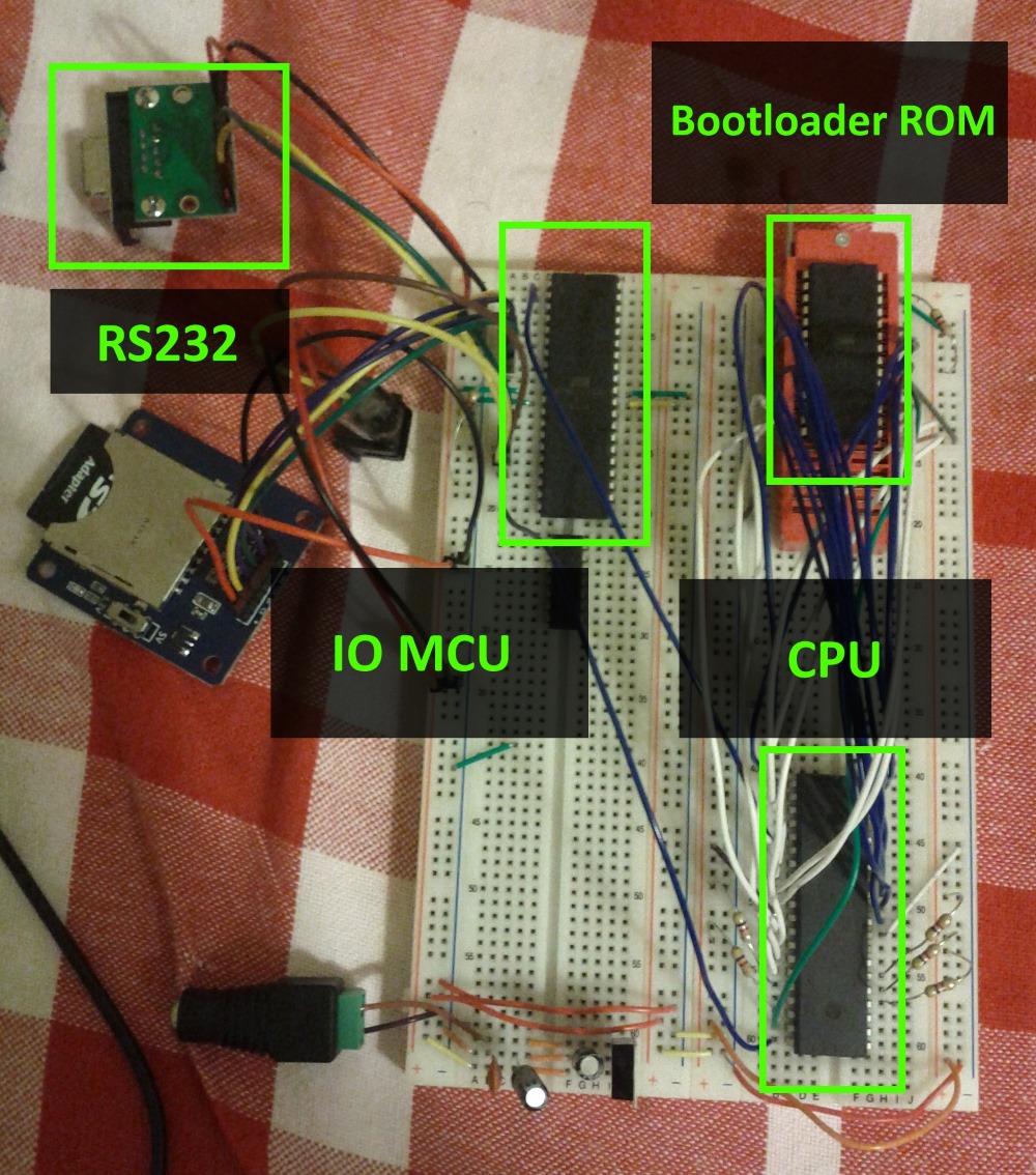
The CPU is connected to a memory chip of 128 kilobytes, of which only 56 kilobytes are available, which is of course nonsense, but I could only get chips of 128 or 32 kilobytes. It turned out that the memory consists of 8 kilobytes of ROM and 56 kilobytes of RAM.
After that, I updated the firmware IO MCU with the help of this library and I have added support for SD cards.
Now the CPU could walk through directories, watch what was in them, open and read files. All this is done by writing and reading to certain I / O space addresses.
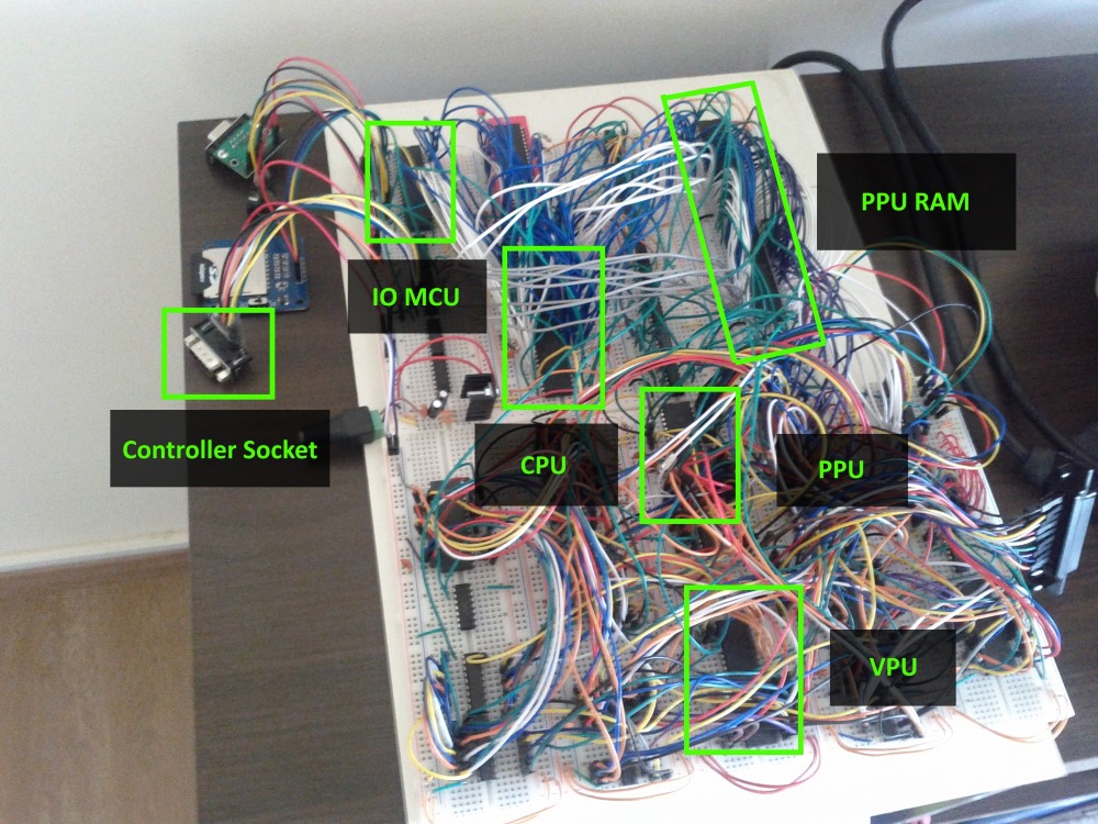
CPU connection to PPU
The next thing I did was the connection between the CPU and PPU. To do this, I applied a "simple solution" which consisted in the acquisition of dual-port RAM, this is such a RAM chip that can be connected directly to two different buses. This allows him to get rid of additional chips like line selectors and, moreover, allows almost simultaneous access to memory from both chips. Another PPU can directly access the CPU on each frame by activating its non-maskable interrupts . It turns out that the CPU receives an interrupt on each frame, which is useful for different timing tasks and for understanding when it's time to update graphics.
Each frame of interaction between the CPU, PPU and VPU occurs according to the following scheme:
- PPU copies information from PPU memory to internal memory.
- The PPU sends an interrupt signal to the CPU.
- At the same time:
- The CPU jumps to the interrupt function and starts updating the PPU memory with a new graphical state. The program should return from interrupt to the next frame.
- PPU renders a picture based on the information previously copied to one of the VRAM.
- VPU sends a picture from another VRAM to the TV output.
About that time I started supporting game controllers, at first I wanted to use Nintendo controllers, but the sockets for them are proprietary and generally difficult to find, so I stopped at 6-button controllers compatible with Mega Drive / Genesis, they have standard DB-9 sockets which is everywhere.
Writing the first real game
At that time, I already had a CPU capable of controlling PPU, working with joysticks, reading SD cards ... it was time to write the first game , of course, on the Z80 assembler, it took me a few days to spend my free time.
Add dynamic graphics
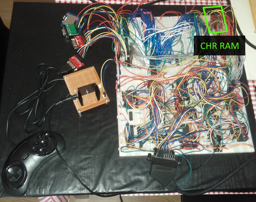
Everything was super, I had my own game console, but this was not enough for me, because I had to use the graphics of the PPU in memory in the game and it was impossible to draw tiles for a particular game and it was possible to change it only by flashing the ROM. I began to think how to add more memory so that the CPU could load symbols for tiles into it, and then PPU could read it all from there and how to do it easier since the prefix was already complex and big.
And I came up with the following: only the PPU will have access to this new memory, and the CPU will load the data through the PPU there and while this boot process is in progress, this memory cannot be used for drawing, but at that time it will be possible to draw from the ROM.
After the end of the CPU load, the internal memory will be switched to this new memory, which I called Character RAM (CHR-RAM) and in this mode PPU will start drawing dynamic graphics, this is probably not the best solution, but it works. As a result, the new memory was installed 128 kilobytes and can store 1024 characters of 8x8 pixels each for the background and as many characters for the sprites.
And finally the sound
Hands reached the sound last. At first I wanted a sound like the one in Uzebox , that is, the microcontroller would generate 4 channels of PWM sound.
However, it turned out that I can easily get vintage chips and I ordered several FM synthesis chips YM3438, these guys are fully compatible with the YM2612 that were used in Mega Drive / Genesis. By installing them, you can get music quality Mega Drive and sound effects produced by the microcontroller.
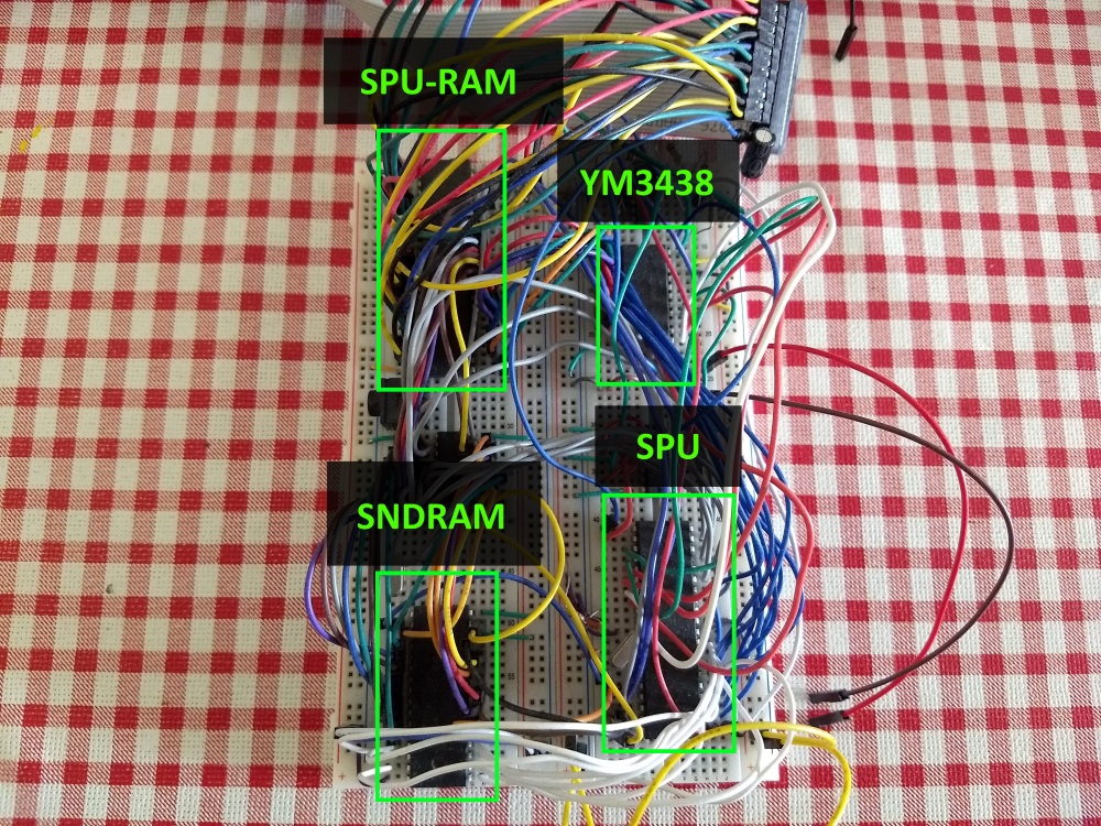
I installed another microcontroller and called it SPU (Sound Processor Unit), it controls the YM3438 and can generate sounds itself. The CPU manages it through two-port memory, this time it is only 2 kilobytes.
As in the graphics unit, the sound unit has 128 kilobytes of memory for storing PCM samples and sound patches, the CPU loads the data into this memory by referring to the SPU. It turned out that the CPU either tells the SPU to execute commands from this memory or updates the commands for the SPU every frame.
The CPU manages four PWM channels through the four circular buffers in the SPU's memory. SPU passes through these buffers and executes commands written to them. There is also one such buffer for the FM synthesis chip.
So, as in the graph, the interaction between the CPU and the SPU goes according to the scheme:
- SPU copies data from SPU memory to internal memory.
- SPU is waiting for the PPU interrupt signal (this is for synchronization)
- At the same time
- The CPU updates the PWM channel buffers and FM synthesizer buffers.
- SPU executes commands in buffers according to the data in the internal memory.
- At the same time with all this, SPU updates the PWM sounds at 16 kilohertz.
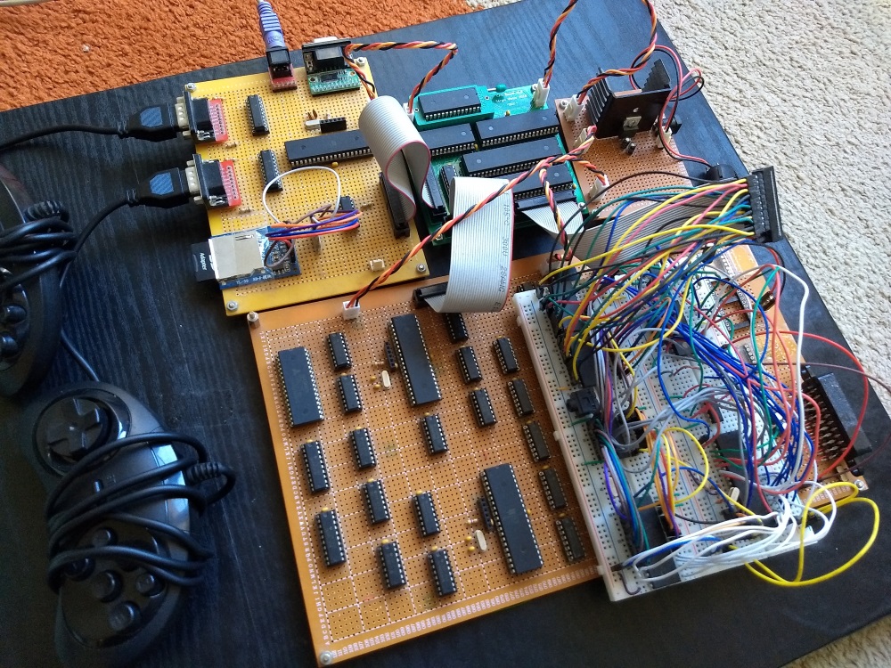
What happened in the end
After all the blocks were ready, some went to the mockups.
For the CPU unit, I was able to develop and order a custom PCB, I don’t know if it’s worth it for the other modules, I think I was really lucky that my PCB started working right away.
On the breadboard, now only sound remains.
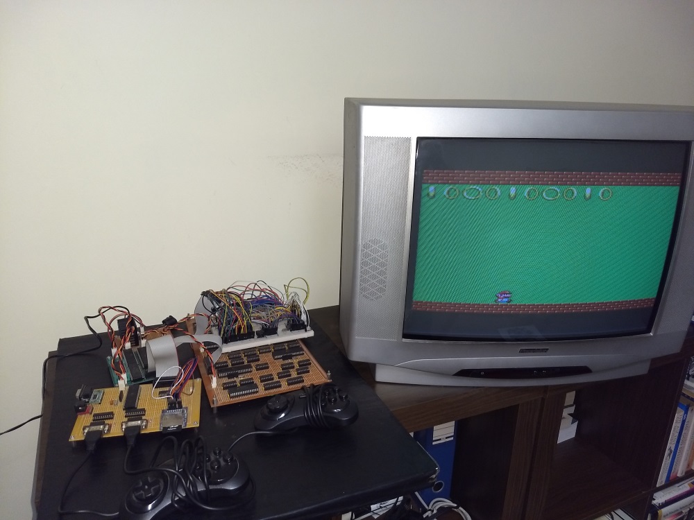
Here is how it looks today:
Architecture
The diagram illustrates the components in each block and how they interact with each other. The only thing that is not shown is the signal from the PPU to the CPU on each frame in the form of an interrupt and the same signal that goes to the SPU.
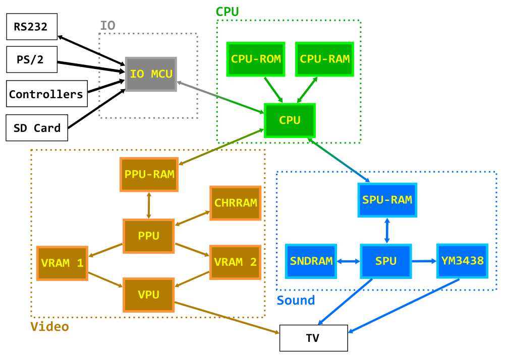
- CPU: Zilog Z80 at 10 MHz
- CPU-ROM: 8KB EEPROM, contains bootloader code
- CPU-RAM: 128KB RAM (56KB available), code and data for programs / games
- IO MCU: Atmega324, is the interface between the CPU and RS232, PS / 2 keyboard, joysticks and SD card file system
- PPU-RAM: 4 kilobytes of dual-port memory, intermediate memory between CPU and PPU
- CHR-RAM: 128KB RAM, stores dynamic tiles for backups (underlays) and sprites (in characters of 8x8 pixels).
- VRAM1, VRAM2: 128KB RAM (43008 is really available), are used for the framebuffer in them it writes PPU and reads VPU from them.
- PPU (Picture Processing Unit): Atmega1284, draws a frame into the framebuffer.
- VPU (Video Processing Unit): Atmega324, reads the framebuffer and generates the RGB and PAL signal and sync.
- SPU-RAM: 2KB dual-port RAM, serves as an interface between the CPU and the SPU.
- SNDRAM: 128KB RAM, stores PWM patches, PCM samples and instruction blocks for the FM synthesizer.
- YM3438: YM3438, FM synthesis chip.
- SPU (Sound Processing Unit): Atmega644, generates sounds on the principle of pulse-width modulation (PWM) and controls the YM3438.
Final specifications
CPU:
- 8-bit CPU Zilog Z80 at a frequency of 10Mhz.
- 8KB ROM for bootloader.
- 56KB RAM.
IO:
- Reading data from FAT16 / FAT32 SD card reader.
- Read / write to RS232 port.
- 2 MegaDrive / Genesis-compatible gaming controllers.
- Keyboard PS2.
Video:
- The resolution is 224x192 pixels.
- 25 frames per second (half FPS from PAL).
- 256 colors (RGB332).
- 2x2 virtual substrate (448x384 pixels), with bidirectional pixel scrolling, based on four full-screen pages.
- 64 sprites with a width and height of 8 or 16 pixels with the possibility of both vertical and horizontal flip.
- The substrate and sprites are made up of characters of 8x8 pixels each.
- Symbolic video memory for 1024 characters for the background and 1024 for sprites.
- 64 independent horizontal scrolling along specified lines
- 8 independent vertical scrolling on specified lines
- An overlay of 224x48 pixels with an optional transparency on the color key.
- The attribute table of the background.
- RGB and composite PAL via SCART connector.
Sound:
- PWM on 8 bits and 4 channels, with built-in waveforms: square, sine, saw, noise and so on.
- Samples of 8 bits, 8 kHz in one of the PWM channels.
- Chip FM synthesis YM3438 downloadable instructions at a frequency of 50 hertz.
Console Development
For the console was written loader. The loader is placed in the CPU ROM and can take up to 8 kilobytes. It uses the first 256 bytes of RAM. The loader is the first thing the CPU executes. It is necessary to show the program located on the SD card.
These programs are in files that contain compiled code and may also contain graphics and sound.
After selecting a program, it is loaded into the CPU memory, the CHR memory and the SPU memory. Then the program code is executed. The maximum size of the code loaded into the console is 56 kilobytes, except for the first 256 bytes, and of course you need to take into account the space for the stack and data.
And this bootloader and other programs written for this console were created in the same way described below.
Memory / IO Mapping
What is important when developing for this console is to take into account how the CPU accesses various blocks, and correctly allocate the address space of the input-output and the address space of the memory.
The CPU accesses the operational and permanent memory of the loader through the memory address space.
Memory address space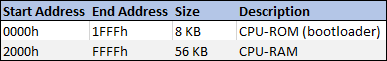
And to PPU-RAM, SPU-RAM and IO MCU through the I / O address space.
I / O address space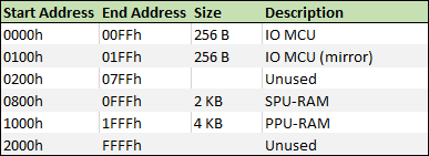
As can be seen from the table, addresses for all devices, IO MCU, PPU and SPU are allocated inside the address space of the I / O.
PPU control
From the information in the table it is clear that to manage the PPU, it is necessary to write to the PPU memory which is available at addresses 1000h-1FFFh in the I / O address space.
PPU Address Space Allocation

PPU Status can have the following values:
- Embedded graphics mode
- Dynamic Graphics Mode (CHR-RAM)
- CHR write mode
- Recording is completed, waiting for confirmation mode from the CPU
Here, for example, how to work with sprites:
The prefix can draw 64 sprites at the same time. Data on them is available through the CPU through the address space I / O address 1004h-1143h (320 bytes), for each sprite has 5 bytes of information (5 * 64 = 320):
- Bytes of different flags, each bit of this byte flag: Active, Flipped_X, Flipped_Y, PageBit0, PageBit1, AboveOverlay, Width16, Height16.
- The character byte, character number from the table (defined by the flags above).
- Color key byte (i.e. what color is transparency)
- X coordinate byte
- Y coordinate byte
In total, to see the sprite, you need to set the Active flag to 1, and set the X and Y coordinates within sight, the 32/32 coordinates put the sprite in the upper left corner of the screen, smaller values hide it or make it partially visible.
Then we can set the character code and transparency color.
For example, if we need to show the sprite number 10, then the address will be 4145 (1004h + (5 x 9)), we write the value 1 for activation and coordinates, for example, x = 100 and y = 120, we write at 4148 the value 100 and by address 4149 is 120.
We use the assembler
One of the programming methods for the console is an assembler.
Here's an example of how to show one sprite and animate it so that it moves and repels from the edges of the screen.
ORG 2100h PPU_SPRITES: EQU $1004 SPRITE_CHR: EQU 72 SPRITE_COLORKEY: EQU $1F SPRITE_INIT_POS_X: EQU 140 SPRITE_INIT_POS_Y: EQU 124 jp main DS $2166-$ nmi: ; (NMI) ld bc, PPU_SPRITES + 3 ld a, (sprite_dir) and a, 1 jr z, subX in a, (c) ; X inc a out (c), a cp 248 jr nz, updateY ld a, (sprite_dir) xor a, 1 ld (sprite_dir), a jp updateY subX: in a, (c) ; X dec a out (c), a cp 32 jr nz, updateY ld a, (sprite_dir) xor a, 1 ld (sprite_dir), a updateY: inc bc ld a, (sprite_dir) and a, 2 jr z, subY in a, (c) ; Y inc a out (c), a cp 216 jr nz, moveEnd ld a, (sprite_dir) xor a, 2 ld (sprite_dir), a jp moveEnd subY: in a, (c) ; Y dec a out (c), a cp 32 jr nz, moveEnd ld a, (sprite_dir) xor a, 2 ld (sprite_dir), a moveEnd: ret main: ld bc, PPU_SPRITES ld a, 1 out (c), a ; 0 inc bc ld a, SPRITE_CHR out (c), a ; 0 inc bc ld a, SPRITE_COLORKEY out (c), a ; 0 inc bc ld a, SPRITE_INIT_POS_X out (c), a ; 0 inc bc ld a, SPRITE_INIT_POS_Y out (c), a ; Y 0 mainLoop: jp mainLoop sprite_dir: DB 0 Use of C language
You can also use the C language, for this we need the SDCC compiler and some additional utilities.
The C code may be slower, but it’s faster and easier to write.
Here is an example of code that does the same thing as the assembler code above, which uses a library that helps make calls to the PPU:
#include <console.h> #define SPRITE_CHR 72 #define SPRITE_COLORKEY 0x1F #define SPRITE_INIT_POS_X 140 #define SPRITE_INIT_POS_Y 124 struct s_sprite sprite = { 1, SPRITE_CHR, SPRITE_COLORKEY, SPRITE_INIT_POS_X, SPRITE_INIT_POS_Y }; uint8_t sprite_dir = 0; void nmi() { if (sprite_dir & 1) { sprite.x++; if (sprite.x == 248) { sprite_dir ^= 1; } } else { sprite.x--; if (sprite.x == 32) { sprite_dir ^= 1; } } if (sprite_dir & 2) { sprite.y++; if (sprite.y == 216) { sprite_dir ^= 2; } } else { sprite.y--; if (sprite.x == 32) { sprite_dir ^= 2; } } set_sprite(0, sprite); } void main() { while(1) { } } Dynamic graphics
(In the original Custom graphics. Approx. Lane.)
In the ROM, the prefix is protected by 1 page of tiles for the back-up and another page of ready-made sprites), by default you can only use this fixed schedule, but you can switch to dynamic.
My goal was to ensure that all the necessary graphics in binary form were immediately loaded into the CHR RAM, and the code in the bootloader from the ROM can do this. To do this, I made several pictures of the correct size with different useful characters:
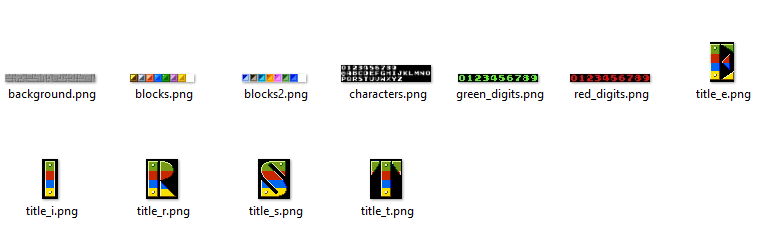
Since the dynamic graphics memory consists of 4 pages of 256 characters of 8x8 pixels each and 4 pages of the same characters for sprites, I translated the pictures into PNG format, deleted duplicate identical ones:
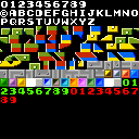
And then I used samopisnuyu tulzu to translate it all into a binary format RGB332 with blocks of 8x8.
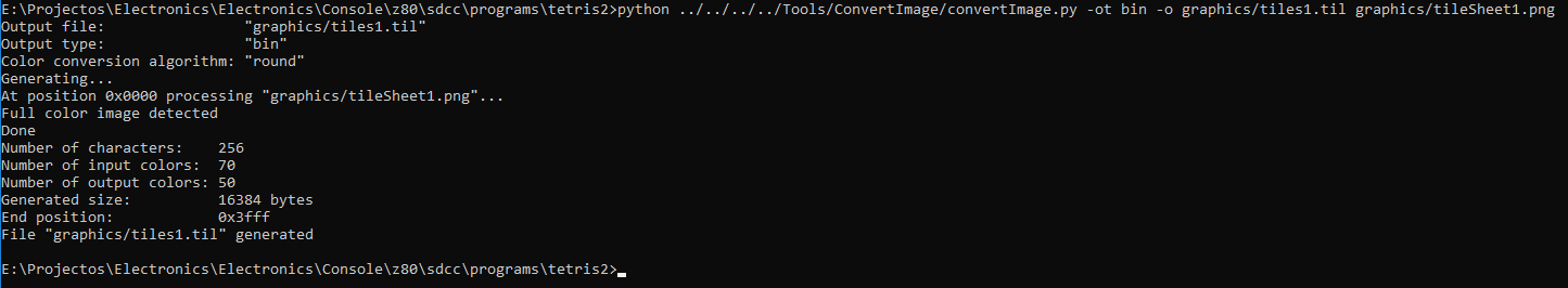
As a result, we have files with characters, where all characters go successively one after another and each occupies 64 bytes.
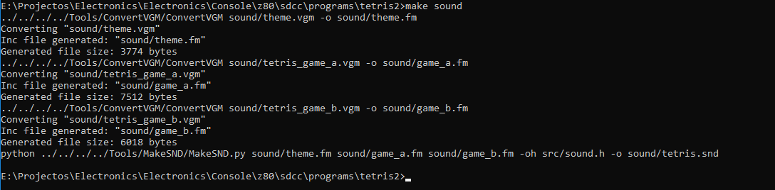
Sound
Wave RAW samples are converted to 8-bit 8 kHz PCM samples.
Patches for sound effects on PWM and music are written with special instructions.
As for the Yamaha YM3438 FM synthesis chip, I found a program called DefleMask, which produces PAL-synchronized music intended for YM2612 chips from Genesis, which is compatible with YM3438.
DefleMask exports music in VGM format and I will convert it with another self-written utility into my own binary format.
All binaries of all three types of sound are combined into one binary file, which my loader can read and load into SDN RAM sound memory.
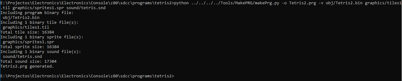
Final File Link
The binary executable code, graphics and sound are combined into one PRG file. The PRG file has a header in which everything is described, whether there is sound and image data, how much they occupy the data itself.
Such a file can be written to the SD card and the prefix loader will read it and load everything into the appropriate places and run the executable program code.
Emulator
I wrote my C ++ emulator using wxWidgets to make it easier to develop for it.
The CPU is emulated by the libz80 library.
Added features for debugging to the emulator, I can stop it at any time and do step-by-step debugging of the assembler, there is a mapping to the C source code if this language was used for the game.
According to the graph, I can look in the video memory, in the character tables and in the CHR memory itself.
Here is an example of a program running on an emulator with debugging tools enabled.
Programming demo
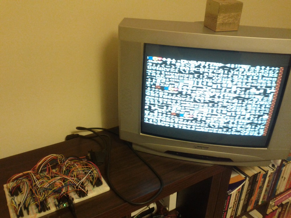
These videos were shot by a smartphone camera aimed at the CRT screen of the TV, I apologize for the non-ideal picture quality.
BASIC interpreter programmable with PS / 2 keyboard, after the first program, I show how to write directly to the memory of the PPU through the I / O address space by activating and moving the sprite:
Graphics demo, in this video, 64 sprite 16x16 are programmatically jumping, against the background of a dynamic scrolling and overlay background that moves under and above sprites:
Sound demo shows the capabilities of YM3438 and PWM sound, the sound data of this demo and FM music and PWM sounds together occupy almost all available 128 kilobytes of sound memory.
Tetris, almost all background features are used for graphics, music on YM3438, sound effects on PWM patches.
Conclusion
This project is truly a dream come true, I have been working on it for several years, with interruptions, looking at free time, I never thought that I would go so far in creating my own retro gaming video consoles. Naturally, it is not perfect, I’m certainly not an expert in electronics, there were obviously too many elements in the console and undoubtedly it was possible to do better, and probably some readers think about it.
But still, in the process of working on this project, I learned a lot about electronics, game consoles and computer design, assembly language and other interesting things, and most importantly I received great satisfaction in playing the games I myself wrote on hardware that I myself developed and collected.
I have plans to do consoles / computers and more. Actually, I am already doing a new set-top box, it is almost ready, and is a simplified retro set-up based on an FPGA board and a few additional components (much smaller than in this project, for sure), intended to be much cheaper and repeatable.
Although I wrote a lot here about this project, there is undoubtedly much more to discuss, I barely mentioned how the sound engine works, how the CPU interacts with it, and about the graphics system and other inputs and outputs and about the entire console as a whole. it would tell.
Looking at the reaction of the readers, I can write more articles focusing on updates, details about individual boxes of the console or other projects.
Projects, sites, Youtube channels that inspired me and helped me with technical knowledge:
These sites / channels not only inspired, but also helped me find solutions to complex problems that arose in the course of working on this project.
Thanks if you have read to here. :)
If you have questions or feedback, write in the comments below (Original article in English on Gitkhab. Note. Lane.)
')
Source: https://habr.com/ru/post/444006/
All Articles