ATtiny13 vs. PLC, or how to get 14 I / O from an 8-foot controller
Before you begin, I would like to warn a zealous reader.
- What I describe cannot be done for many reasons, these reasons you will happily indicate in the comments, and I in no way urge to do so. And in no case do I claim that the device described below can be replaced with a real PLC. Everything described has been done only to prove to itself that this is technically possible, and is not used on real equipment.
- If you only feel bad at the mention of the word "Arduino", you better not read. I performed all the actions with the controller in the Arduino IDE, it's easier for me. But nothing prevents to do the same without using it.
I have long wanted to write an article about my experiments with ATtiny13, but first of all I was frightened by the attitude to the Arduinkers on the site. Moreover, I have been working on controllers for only a few years (thanks again to Arduino, oh, where have you been before!). Comments on the article. Three eyes hang on a pole ... showed that the topic is still interesting to a sufficient number of users. By the way, the title of the article “PLC on ATtiny13” was supposed, but in the same comments, they were politely explaining my
')
What do we need from the PLC?
It began with the fact that I wanted to make a functional analogue of the PLC, which are used in my company, taking into account how they are used. Most of the control circuits are relayed with all the ensuing disadvantages. PLCs of different types are used in the same places, starting from the 90s. Basically, they perform the logical task of the control circuit, starting from the state of the limit switches and proximity sensors.
No complicated interfaces, no analog signals. On Off. Everything. Even the load for the PLC outputs is for the most part the same relays that they were trying to get rid of. (The most fun thing is that almost everywhere PLC relay outputs are used, which commute external relays, which electromagnets of hydraulic distributors commute ... Sometimes one more link from the actuator is added.) So, what do I need from the PLC:
- Discrete inputs under the signal level of 24 volts.
- Discrete outputs with a voltage of 24 volts.
- The development of the internal algorithm according to a given scheme, which can be changed if necessary (mainly during the debugging process).
- The speed of the order of 50 ms, to replace the relay circuits is no longer necessary.
And that's all. No interfaces. No interruptions. No screens. Oh, yes, the screens ... It does not hurt to display the status of the inputs and outputs, there is nothing more reliable here than the LEDs. Well, do not forget that everything is done from sports interest, respectively, the budget falls on the shoulders of the developer. By the way, a very good incentive.
If you do not take into account the signal level of 24 volts, then the task is easily handled by absolutely any microcontroller with the number of I / O (I / O) is not less than the required.
Understanding the levels
Initially, I wanted to use optocouplers at the inputs. Anyone who is more or less versed in electronics, especially industrial, knows that there are not many optocouplers. The comments will tell you in detail why it is impossible without optocouplers. But I weighed all the pros and cons, and decided to refuse. So some may not continue to read, and immediately go to write a comment.
So, we have an input signal of 24 volts, or 0 volts in the absence of a signal. This will allow the use of a non-contact inductive position sensor or a conventional contact limit switch. From 24 volts, you need to get a logical unit voltage safe for the controller. Good old voltage divider copes with this as well as possible.
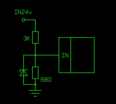
The resistors are calculated taking into account that for any deviations of the input voltage by plus or minus 20% of the nominal voltage of the microcontroller input there is more switching voltage (usually half of the controller supply voltage), but not more than the controller supply voltage, we consider it equal to 5 V. Suitable for any controller of the AVR family. In addition, the estimated current through the divider is about 7 mA, which reduces the likelihood of interference and does not load the output of the sensor and the power supply much. The zener diode for a voltage of 4.7 V is used to protect against impulse overvoltages during the same interference. There is still a bounce of contacts, with it we can fight programmatically or not fight at all, this is just a layout. Now I would also make an indication of the state of the input. And here you can use life hacking, killing two birds with one stone:

The LED on the circuit performs two functions, works as a zener diode, limiting the voltage at 2.8 ... 2.9 volts (only for blue and white LEDs!), Well, and shines to the same. I must warn you that in some cases the voltage on the LED is not enough to switch the input of the controller! When using multiple controller inputs, we thus simplify installation and save several zener diodes. Gradually increasing the voltage at the input, you can see that the moment of ignition of the LED and the moment of switching the input do not coincide a bit. But it doesn’t really bother us, as there should be no intermediate levels at the input - only 0 V or 24 V. Naturally, by this time you should have at least the minimum test firmware for one input and one output in the controller.
Now the output signal from the controller also needs to be adapted for 24 V, and taking into account that the common wire, which is also a minus, is common to all output relays. Here you need at least 2 transistors and 2 resistors:
scheme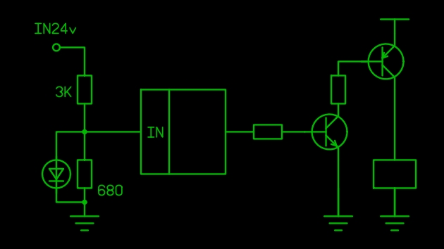
In fact, we would need another resistor, and a protective diode parallel to the relay, but this is not about that now. At first, I used this scheme. But at one point I paid attention to optocouplers, which I refused at the beginning.
The one who bothers us will help us
scheme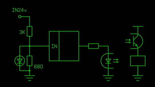
We look at the parameters of optocouplers on datasheets: the cheapest and most affordable PC817C output allows you to switch U out: 35 V: I out: 50 mA. Those relays that are connected to the PLC from us (in the enterprise), take up to 45 mA. Without stock, but quite suitable. Most of the small 24 V relays pull up to 15 ... 20 mA. In the end, you can buy an optocoupler more expensive, if you really need, there is a current up to 80 mA, and a voltage up to 60 V. We are suitable for the layout and 817. So that you do not learn from your mistakes, I warn you that you need to pass more than 7 mA for the maximum output current through the LED of the optocoupler.Well, again, remember the display. To display the output status, we add a LED in series with the LED of the optocoupler, we still have more than 3 volts falling idle there. And it's time to draw a protective diode, until you burned the optocoupler. By the way, I could not find a method for selecting a protective diode depending on the parameters of the relay. On the one hand, it should be pulsed, on the other, high-voltage. In addition, it can be put parallel to the transistor, as better? Practice shows that IN4148 is a fairly low-power diode in this case, but I would like a theoretical justification.
scheme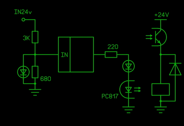
The 220 ohm resistor is listed with the calculation again on a blue or white LED, if you put red, the current in the circuit from 3.5 mA will increase to 9 mA, this should be taken into account.
Something about programming
Well, so many letters, but I still have not gotten to the essence of the title, nor to ATtiny13. For programming my controller, I used the FLProg project , a visual programming environment that approximates the programming of the controller to PLC programming in LAD and FBD languages. The scheme created in this environment, it’s the same project, is compiled into the Arduino sketch, which I’m uploading from the Arduino environment to ATtiny13 or another controller of the AVR family. For example, such a simple scheme
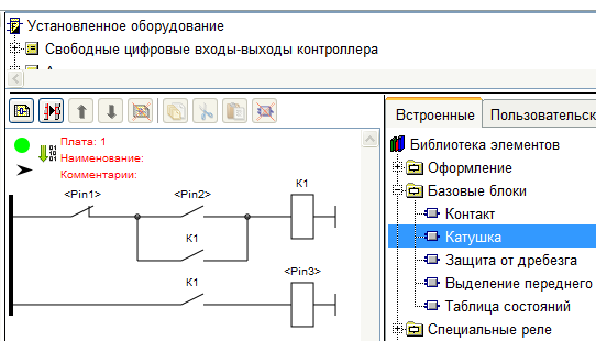
compiled into this code:
bool _k1 = 0; void setup() { pinMode(1, INPUT); pinMode(2, INPUT); pinMode(3, OUTPUT); } void loop() { _k1 = (((((!(digitalRead (1)))) &&((digitalRead (2))))) || ((((!(digitalRead (1)))) &&(_k1)))); digitalWrite (3, _k1); } Try to write all the same manually - one bracket somewhere missed, and all for nothing. Many thanks to the creator of the FLProg project Sergey Glushenko, his program has greatly influenced my “work” over the past three years. Arduinschikam everything should be clear and true, and the rest do not know how to explain. The only pin on the diagram and in the code is the controller pins in the Arduino environment, their numbering differs from the numbering of the legs. How to put all this in ATtiny13, is detailed here: Updated Attiny13 or Attiny13a Programming Guide with Arduino IDE Yes, another trifle: FLProg still doesn’t support ATtiny13 (I think we should add it soon) another controller, for example ATmega168. Just FLProg will offer to use pins that ATtiny13 doesn’t have, but you can choose not to take them. And in the Arduino IDE, you need to install the correct type of controller, otherwise it will not work.
Well, about the most important thing
What do we have in the end? We have ATtiny13, in which 5 legs are available for use, which we can designate as entrances or exits. If you really want to, you can use 6 legs, but it is fraught, we read here, for example: Few conclusions? Use RESET .
Well, we get 6, still not enough. How to get more?
That's how:
scheme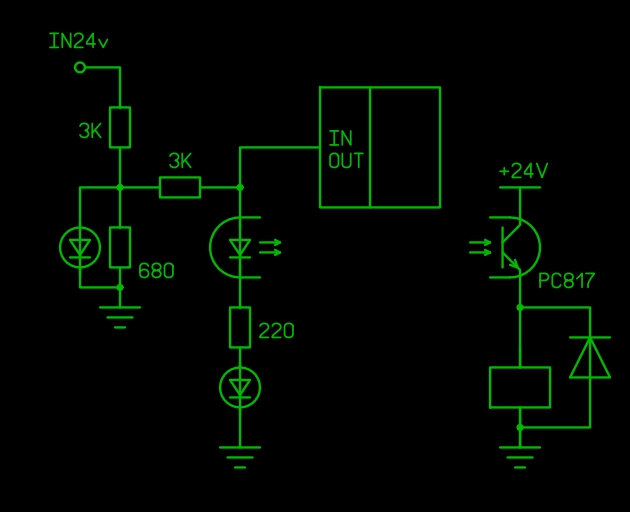
You can see that just the input strapping and output strapping are connected to the same pin. Now turn to the software part. And the software part will be even without code, in order to avoid its criticism. Just an algorithm.
I have already mentioned that the speed of the circuit is about 50 ms. This means that once every 50 ms, it is enough to quickly interrogate the status of the inputs, then assign them to the outputs, and submit the required level to these outputs. Then we assign the outputs to the inputs, and repeat the process.
During the polling at the input divider we have 0 volts or 2.8 V, the same voltage is applied to the input of the microcontroller, in any case, this is not enough for current to flow through the output chain. In order for the current to go through the output circuit, a voltage of at least 1.1 V is necessary (a drop on the LED of the optocoupler) plus 2.9 V, for a total of at least 4 volts. Accordingly, there is no current at this moment, the transistor is closed.
Further, the entrance became the exit. If the output is in the state of logical zero, again no current flows through the output circuit, the transistor is closed. If the output is in the unit state, then the voltage on it is close to the power supply, that is, about 5 V, respectively, through the output chain, the LED of the optocoupler-resistor-LED flows a current, which opens the transistor of the optocoupler and turns on the relay. Part of the current at the same time flows through 3 kOhm resistors (which is horizontal in the diagram) and 680 ohms. But falling on the resulting divider is not enough to light the LED of the input circuit. If at this time the input level is high, the input LED is lit, and a small current from the controller pin is added to the input circuit current.
What do we have in the end? With a high output level, the relay is turned on 50 ms, then off for less than 1 ms, and turned on again 50 ms. Of course, in 1 millisecond the relay does not have time to switch off, it will disappear only if the output is found most of the time in the zero state. The optocoupler transistor does not like this situation very much, a diode to help it.
The scheme is tested in work, it functions not only in theory. A few more details are being asked for reliability, the absolutely necessary minimum is on the diagram.
But we only get 6 + 6 = 12 inputs-outputs, where to get 2 more?
again scheme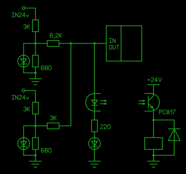
Well, you understand the logic? Here we will need an analog input, we have them) and as many as 4 pieces, however, one again on the reset leg, let's leave it for a rainy day. In the pin of the microcontroller, in the polling mode of the input state, the voltage is 0 volt, if both inputs are low, and 2.8 volts, if both inputs are high (we already passed this higher). But if on one of them 24, and on the other 0, or vice versa, we get another 2 intermediate values - 0.93 V or 1.87 V. It remains only to compare the obtained value to meet certain limits, and assign the state of the inputs to variables in the program. In the Arduino IDE environment, all this is done rather slowly and resource-intensive, but even so I have almost half of ATtiny memory left, and a satisfactory speed. You can write everything in assembly language, and it will be even cooler.
So, as you can see, 6 outputs and 10 inputs (!) Can be obtained from ATtiny13 even without register microcircuits (I also had this experience). Of course, there is little practical benefit from this; debugging such a device is very inconvenient. Although it is possible to debug on the controller with a large number of legs, and the finished circuit can be “filled in” with ATtiny. Well, it is economically more expedient to do the same on the ATmega8, and without dancing with tambourines. But the pleasure is not that :-)
And if you are missing a pair of legs of a microcontroller to change an existing device, you can use one of the suggested options.
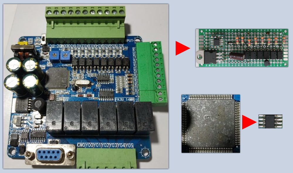
PLC on KDPV is not related to this publication, I just did not give a photo of the real PLC used in my company, so as not to accidentally offend the manufacturer. But the amount of I / O on it corresponds to the task. By the way, these figures (8/6) appeared from a specific task, on which I wanted to test my non-PLK, in order not to talk about "spherical horses in a vacuum."
Well, if I do not spit after the first publication, perhaps I will write about my more practical experience of “PLC Construction”, with photos and
PS If you look at the schemes in the article and think: “What does that remind me of?”
here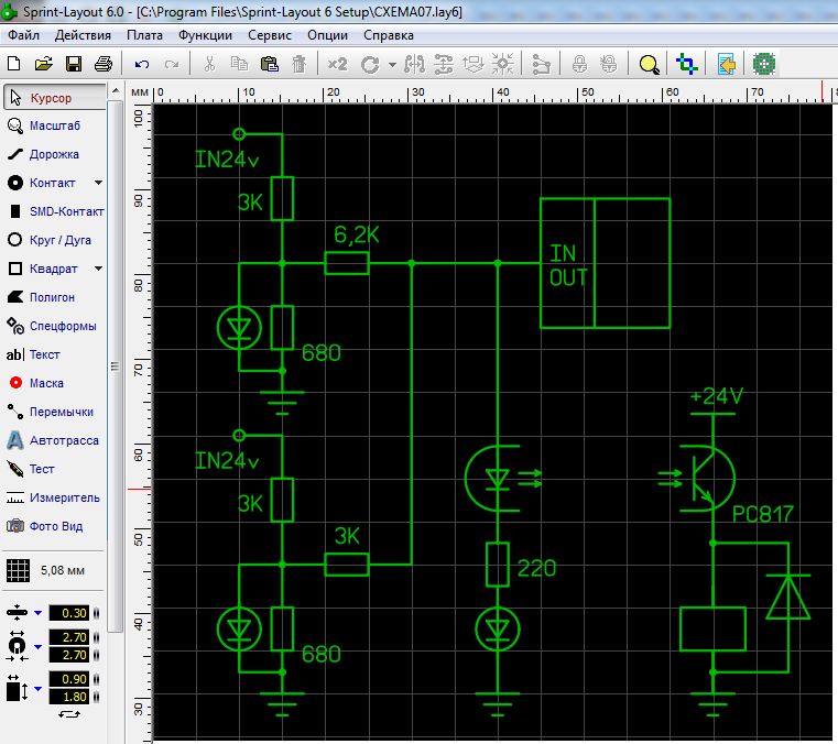
Source: https://habr.com/ru/post/443978/
All Articles