Review of the new features of nanoCAD SPDS Metalware version 1.2
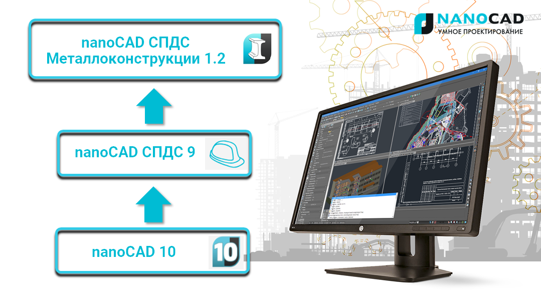
Last fall, the company Nanosoft, JSC introduced the latest version of the vertical application nanoCAD SPDS Metal Structures 1.2, created to develop two-dimensional drawings of metal structures of the brand KM. You can get acquainted with the functionality in detail in the product description of nanoCAD SPDS Metal structures or in the article “ nanoCAD SPDS Metal structures. Full work on the creation of 2D drawings of the brand KM . The subject of this article is the new functionality of nanoCAD DPS Metalware version 1.2. When developing a new version, special attention was paid to the recommendations and wishes of users - upon their requests, changes were made to the work of the program tools. Significant improvements have also been made in the dynamics of the workflow - this is the new nanoCAD Plus 10 graphics platform with a new video driver and a new ribbon interface. As a result, in the new version, users will try modern and convenient tools of the program, they will feel a noticeable increase in the processing speed of drawings saturated with parametric objects, texts, blocks and other complex primitives.
But this is far from everything, users are also provided with the entire set of necessary tools for drawing up drawings, this is the built-in functionality of nanoCAD SPDS 9, unlimited creative freedom to develop project documentation and, of course, the ability to finish work on a project within a specified period.
')
First of all, I would like to mention the new ribbon interface, which provides modern standards of user interaction with the program. Tools icons nanoCAD Metal structures in the tape are informative and compactly arranged, it gives the user the most comfortable work with the tools. But if you are used to working with the classic interface, it is possible to quickly change it with the help of an instantaneous switch button.

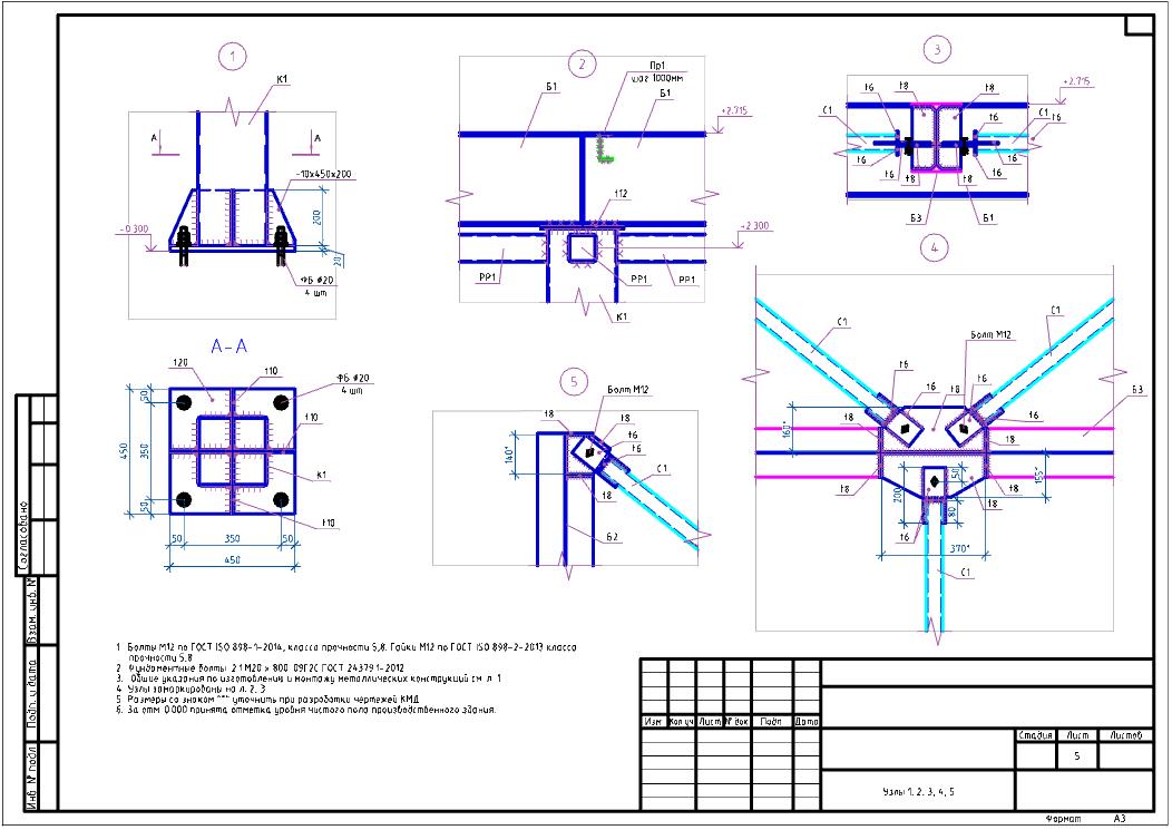
To simplify and optimize the design, the program implements work with such parametric objects as a column, a beam, a plate. The user can select various metal-roll profiles according to GOST standards, select the type of projection he needs (top, bottom, front, etc.), and also use special “pens” to edit the profile length or change the geometry of the plate.
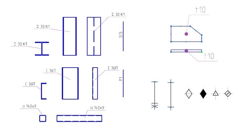
As for the functionality of the Project Manager, there have been dramatic changes in the direction of increasing the information content of the project. A new column Count has appeared, where those structural elements that will be included in the specification are now shown. In the column Name the icons of the designation were changed. Now for each type of profile section, its own icon, which schematically in the form of a section displays this profile. These changes, of course, will help the user not only to control the entire composition of the project, but also to easily navigate a large variety of rolled metal profiles.

Sooner or later, the user is faced with such a problem as the presence in the drawings of a significant number of elements of the same brand, which are repeated or even represented in other types or sections. It was quite problematic to understand the huge number of identical brands, and even more so to know which brands should be included in the specification. This problem was successfully solved by the developers, and the new version of the program now has the opportunity directly from the Project Manager to indicate which element brand should be included in the specification. For convenience, a two-way communication is implemented between the project manager and parametric objects, where the selected brand in the Project Manager automatically highlights this position in the drawing, which makes it much easier for the user to find the elements.

The beam / column dialogue was not ignored: the switch to the Main central axes was added to the View tab. Now it became not only fast, but also convenient to install or remove the central axes for profiles.

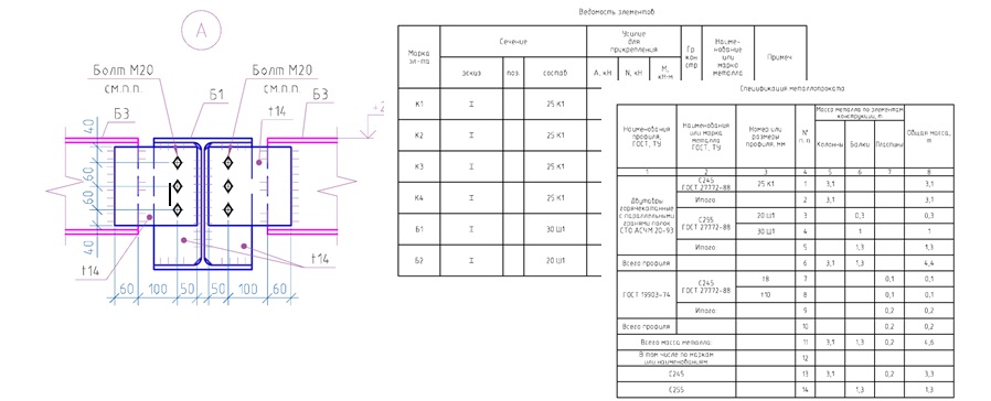
For the case when the project is nearing completion and it is necessary to obtain a specification with the accuracy we need, it is possible to adjust the rounding of the metal mass. Now, when working with the metal-roll specification, the user can configure the rounding parameters he needs for him.

In conclusion, I would like to note that the nanoCAD SPDS Metal Construction 1.2 program is a simple and convenient tool with extensive functionality that takes 2D design to a new level. This software product allows us today to significantly accelerate the release of design documentation of the KM brand and reduce the number of design errors.
nanoCAD SPDS Metalwork 1.2 is compatible with 32 and 64-bit versions of Windows 10, Windows 8.1 and Windows 7. To work, you need a PC based on an Intel Core i3, i5 or i7 processor or equivalent AMD Athlon processor. A discrete graphics card with support for OpenGL / DirectX-compatible 3D hardware acceleration and video memory size of 1024 MB or more. It is recommended to use the latest video drivers from the manufacturer of the video card and the latest versions of the OpenGL / DirectX libraries. You must have at least 2 GB of RAM and 1 GB of free hard disk space, a mouse, and a monitor with a resolution of at least 1024x768 or higher.
 Dmitry Gostev, Leading Engineer, Magma Computer
But this is far from everything, users are also provided with the entire set of necessary tools for drawing up drawings, this is the built-in functionality of nanoCAD SPDS 9, unlimited creative freedom to develop project documentation and, of course, the ability to finish work on a project within a specified period.
Tasks that are solved by the program nanoCAD DPS Metal Structures:
- Registration of plans for plans, sections, metal structures;
- The ability to create various structural solutions of metal structures;
- Automatic formation of the list of elements and specifications of metal;
- Design of drawings in accordance with GOST 21.502-20016 “Rules for the execution of the working documentation of metal structures”.
')
Key advantages of the new version of nanoCAD DPS Metal structures:
- Fast and flexible tools for applying and editing metal frame elements;
- Automatic assignment of positions, brands and their display on the drawing;
- Fully automatic calculation and formation of specifications;
- Work in the nanoCAD environment using the built-in functionality of the nanoCAD SPDS.
Let's take a closer look at the main changes in the program.
First of all, I would like to mention the new ribbon interface, which provides modern standards of user interaction with the program. Tools icons nanoCAD Metal structures in the tape are informative and compactly arranged, it gives the user the most comfortable work with the tools. But if you are used to working with the classic interface, it is possible to quickly change it with the help of an instantaneous switch button.
To simplify and optimize the design, the program implements work with such parametric objects as a column, a beam, a plate. The user can select various metal-roll profiles according to GOST standards, select the type of projection he needs (top, bottom, front, etc.), and also use special “pens” to edit the profile length or change the geometry of the plate.
As for the functionality of the Project Manager, there have been dramatic changes in the direction of increasing the information content of the project. A new column Count has appeared, where those structural elements that will be included in the specification are now shown. In the column Name the icons of the designation were changed. Now for each type of profile section, its own icon, which schematically in the form of a section displays this profile. These changes, of course, will help the user not only to control the entire composition of the project, but also to easily navigate a large variety of rolled metal profiles.
Sooner or later, the user is faced with such a problem as the presence in the drawings of a significant number of elements of the same brand, which are repeated or even represented in other types or sections. It was quite problematic to understand the huge number of identical brands, and even more so to know which brands should be included in the specification. This problem was successfully solved by the developers, and the new version of the program now has the opportunity directly from the Project Manager to indicate which element brand should be included in the specification. For convenience, a two-way communication is implemented between the project manager and parametric objects, where the selected brand in the Project Manager automatically highlights this position in the drawing, which makes it much easier for the user to find the elements.
The beam / column dialogue was not ignored: the switch to the Main central axes was added to the View tab. Now it became not only fast, but also convenient to install or remove the central axes for profiles.
For the case when the project is nearing completion and it is necessary to obtain a specification with the accuracy we need, it is possible to adjust the rounding of the metal mass. Now, when working with the metal-roll specification, the user can configure the rounding parameters he needs for him.
In conclusion, I would like to note that the nanoCAD SPDS Metal Construction 1.2 program is a simple and convenient tool with extensive functionality that takes 2D design to a new level. This software product allows us today to significantly accelerate the release of design documentation of the KM brand and reduce the number of design errors.
System requirements:
nanoCAD SPDS Metalwork 1.2 is compatible with 32 and 64-bit versions of Windows 10, Windows 8.1 and Windows 7. To work, you need a PC based on an Intel Core i3, i5 or i7 processor or equivalent AMD Athlon processor. A discrete graphics card with support for OpenGL / DirectX-compatible 3D hardware acceleration and video memory size of 1024 MB or more. It is recommended to use the latest video drivers from the manufacturer of the video card and the latest versions of the OpenGL / DirectX libraries. You must have at least 2 GB of RAM and 1 GB of free hard disk space, a mouse, and a monitor with a resolution of at least 1024x768 or higher.
Dmitry Gostev, Leading Engineer, Magma ComputerSource: https://habr.com/ru/post/443872/
All Articles