PRP and HSR seamless redundancy protocols
In industry, the requirements for LAN are becoming more serious, because Process control systems take on more and more functionality, and data loss can entail significant costs.
For example, in the power industry, if the data from the measuring transducers do not fall on the RZA terminal, this may be fraught with the propagation of a short circuit to adjacent parts of the power grid, which will result in losses much more serious than in the case of timely disconnecting the section from the short circuit. Therefore, it is often possible to meet the requirement “Recovery time less than 1 ms” in energy projects.
Network redundancy based on industry-wide protocols such as RSTP, MRP, DLR, and the like, is based on a topology change in the event of any data transfer failure. Changing the topology takes a certain time (from milliseconds to seconds depending on the protocol), which is called the “recovery time”. During this time, there is no connection with part of the network and, accordingly, data is lost. Those. Conventional ring backup technologies do not allow recovery times of less than 1 ms.
In view of this, the technology of the so-called "seamless" redundancy is gaining popularity - PRP and HSR. The redundancy on the basis of PRP and HSR is carried out, in contrast to the above-indicated protocols, not by rebuilding the topology, but by duplicating frames. Each frame is duplicated by the sender, and both frames are transmitted in different ways, and the receiving node processes the frame that came first and discards the second one. This principle does not require rebuilding the topology and, accordingly, this protocol acts almost seamlessly. Under the cat you will find details of the implementation of these protocols.
')
A seamless reservation is implemented on the end nodes, not on network components. This is one of the most important differences between PRP and HSR from other reservation protocols such as RSTP or MRP. Consider the features of the network structure for PRP and HSR.
The end node has two Ethernet interfaces that are connected to two networks isolated from each other, operating in parallel and having an independent topology (i.e., the topologies of these two networks may be the same or different). The networks must be isolated so that any malfunction and interruption of data transmission on one network does not affect the second, i.e. even the networks are powered from different sources. There should be no direct connections between these networks.

PRP network structure
These two networks are commonly called LAN A and LAN B. As already indicated, they may have different topologies, as well as different performance. Data transfer delays may also vary.
The network may contain the following elements:

The principle of RedBox
HSR network structure
The principle of operation of HSR is that all devices are combined into a ring and all messages, as well as in PRP, are duplicated. The device sends both frames through the ring: one copy is clockwise, the other is against. The receiver receives both copies, but processes only the first, and the second deletes. If something happens to any of the links, and one of the duplicate frames does not come, then the other is simply accepted. All HSR devices have two Ethernet interfaces — port A and port B.
In accordance with the HSR protocol, the following elements may exist in a network:

QuadBox usage example
For PRP and for HSR, the DAN structure is similar. Each DAN has two interfaces operating in parallel and connected to the top level of one communication stack through the so-called LRE level - link redundancy entity. All redundancy functions are performed at this level.
Both DAN interfaces have the same MAC address and one IP address. This makes the reservation transparent to the top level. Especially important is the fact that it allows the use of ARP for DAN as well as for any unreserved node.
However, of course, there are some nuances in the DAN structure for PRP and for HSR.
When a frame is sent from the top level, LRE duplicates it and sends both packets through the ports almost simultaneously. Both frames are transmitted in parallel through two networks with different delays. In an ideal situation, they are delivered to the destination site with a minimum time difference. Upon receiving the receiver LRE, the first received frame is transmitted to the upper layer, and the second one is discarded.
LRE creates duplicate frames when sending and processes them when received. This layer, in relation to the upper layer, is a normal interface of a non-redundant network adapter. LRE performs two tasks: handling duplicate frames and managing backups. To implement the control, LRE adds a 32-bit redundancy control trailer (RCT) to each frame and deletes it when the frame is received.
Data transfer between two DAN to PRP
The frame sent from the top level is duplicated by the LRE layer, and the packets are sent through port A and port B almost simultaneously. (1 and 2 in the diagram).
When receiving a frame, the receiver transmits it to the LRE level, and also redirects to another port and transmits further in the ring. (3, 4).
If the frame arrives at the sender, then this frame is not transmitted further, but is destroyed (5, 6).
Both frames arrive at the LRE level, but the one that was sent faster is transmitted to the upper level, and the duplicate frame is dropped.
LRE adds a 48-bit HSR tag to each frame (akin to adding a VLAN tag) and deletes this tag when received.
Data transfer between two DANs in HSR
A PRP SAN can be connected to any network — LAN A or LAN B, but such a node does not support redundancy features. Therefore, a SAN connected to one network will not be able to communicate with another similar node connected to the second network. For interaction with SAN, DAN generates special frames. This need is caused by the fact that a SAN in a normal frame from a redundant device must ignore the RCT, which is not possible, since the SAN cannot distinguish the RCT from the normal IEEE 802.3 data block. In turn, the DAN understands that it sends a frame to the SAN and does not add the RCT to the frame. It simply sends one frame from the top level to the interface to which the SAN is connected. In other words, if the DAN cannot determine what is communicating with another DAN, then it does not add the RCT to the frame.
In HSR, a SAN cannot be directly connected to the network. It can only be connected via RedBox.
When working with duplicated frames received on both interfaces (if they are healthy), the DAN must be taken in one of the frames and the second discarded. PRP has two processing methods:
For HSR, consider the most popular modes U and X
DAN operating in this mode does not drop any of the frames during link level processing.
Frames are sent to LAN A and LAN B without RCT. The receiver LRE simply redirects both frames to the upper level, assuming that on further transmission duplicates will be destroyed (IEEE 802.1D clearly states that the upper level protocols must be able to handle duplicate frames).
For example, TCP and UDP protocols have a high level of resistance to duplicate frames.
This method is very simple to implement, but it has a serious drawback - it does not provide any network monitoring capabilities, since in no way monitored the correctness of the reception of both frames.
When using the second method, a field consisting of four octets - RCT (redundancy control trailer) is added to the frame. The trailer is added at the LRE level when the frame is received from the top level. RCT consists of the following parameters:
Due to the addition of an RCT trailer to the frame, its size is larger than the maximum frame size specified in the IEEE 802.3-2005 standard. To transmit data within a network with a PRP, the equipment must be configured to transmit data in the size of 1496 octets. Because of this, not every switch is suitable for use on LAN A or LAN B.
RCT frame added
Each time a link layer sends a frame to a specific address, the sender increments the sequence number for the corresponding node and sends identical frames through both interfaces.
The receiving node shall determine duplicates based on information from the RCT.
The receiver assumes that frames sent from any source operating under the PRP protocol are sent sequentially with an ever-increasing number. The sequence number that is expected for the next frame is stored in the variables ExpectedSeqA and respectively ExpectedSeqB.
Upon receipt, the sequence correctness can be checked by comparing the value of ExpectedSeqA (ExpectedSeqB) with the sequence number of the received frame stored in the variable currentSeq in the RCT. If the result is positive, the ExpectedSeq variable is set to one more than the currentSeq in order to be able to perform a correct check on this line.

Frame drop interval (drop window)
For both interfaces, there is a dynamic frame drop interval (sliding drop window) for paired sequence numbers. The upper boundary of this interval is ExpectedSeq (the next expected sequence number on this interface), excluding this value itself, and the lower boundary of this interval is startSeq (the smallest sequence number at which the duplicate frame is dropped with that sequence number).
After checking the correctness of the sequence number, the receiver decides to discard this frame or not. Suppose that LAN A has a non-zero frame dropping interval (Figure 5). A frame from LAN B whose number lies in this interval will be dropped. All other frames from LAN B will be received and sent to the upper level.
By discarding the frame from LAN B, the size of the LAN A interval is reduced, since after receiving this frame, no frames with a lower number are expected on this interface. Accordingly, startSeqA is set to one more than currentSeqB. In this case, the size of the drop interval of the LAN B frame is reset to 0 (startSeqB = expectedSeqB), since it is obvious that LAN B frames are “behind” LAN A and no frames from LAN A should be dropped.
Reducing the LAN A interval after dropping a frame from LAN B
In the situation of Figure 7, when several frames from LAN A come in succession, but nothing comes from LAN B, they are accepted because their currentSeq is outside the drop interval of the LAN B frame and the LAN A interval is increased by one position. If frames from LAN A continue to arrive, and still nothing comes from LAN B, when the maximum interval size is reached, startSeqA also begins to increase by one.
When the received frame is outside the frame’s drop interval of another LAN, this frame is saved, and the interval size of this interface is set to 1, which means that only a frame from another LAN with the same sequence number will be dropped, while the drop window of another interface is set to 0, which means that no frame will be dropped (Fig. 7).
Frame from LAN B has not been dropped
The most common situation is when both interfaces are synchronized and the size of both intervals is 0 (Fig.8), which means that the frame of the interface that comes first will be accepted and the interval of this interface will be increased to 1, which will allow you to drop the frame from another interface from same sequence number.

Synchronized LAN
Due to the presence of a LAN identifier in the RCT, duplicate frames differ by one bit (and have different checksums). The receiver checks the frame for the interface (i.e., checks that the frame with the identifier LAN A has arrived at interface A). The receiver will not discard this frame, since it may contain useful information in the data block, but in this case the counter cntWrongLanA or cntWrongLanB will be increased by one. Since such errors are not one-time errors (they are confused with LAN A and LAN B), the counter will increase constantly.
When transferring data within the HSR network, an HSR tag is added to each frame.
An HSR tag consists of the following parameters:
The sender inserts the same sequence numbers to the duplicate frames sent, and then increments the sequence number for each parcel sent from this node.
The receiver keeps track of the sequence numbers of all frames from each source from which it receives data (it distinguishes sources by MAC address). If frames come from different lines and have the same source and sequence number, one of them is received, and the second is discarded.
To control the network, on each device is a table of all nodes in the network from which it receives data. This allows you to detect the disappearance of nodes and errors on the bus.
The node determines the frame that it sent to the source and the sequence number.

HSR tag added frame
The HSR node never drops a frame that it has not previously received. The node defines almost all duplicated frames, but if there are not many of them, it does not delete them, i.e. the frame simply passes the entire ring and is destroyed on the sender.
In the standard, the algorithm for determining duplicate frames is not defined. As possible methods, hash tables, queues, and tracking of sequence numbers can be used.
In this mode, the node that receives the frame destroys the duplicate and does not allow it to spread further. If the frame is still transmitted further, it is destroyed on the following nodes. This mode allows you to unload the ring from Unicast traffic.
In the diagram, red arrows indicate packets with HSR-tag sent from port “A” (hereinafter referred to as frame “A”).
Green arrows indicate packets with HSR-tag sent from port “B” (hereinafter referred to as frame “B”).
Empty arrows indicate dropped traffic, i.e. frames that would be transmitted during normal operation, but in this mode were dropped.
Cross indicates the removal of traffic from the ring (in any case).
In this mode, the node does not transmit the frame further and discards it if such a frame was received from another direction.
For example, DAN 1 in the image will not transmit frame “B” further, since he has already received the frame “A”, and DAN 2 will not transmit further the frame “A”, since already received frame “B”.
If an error occurred somewhere in the algorithm and the frames were transmitted further, they will be dropped on the following nodes or on the node on which they were created.
X mode is not applicable for PTP messages and for transmission frame.
The receiver checks that all frames arrive consistently and correctly received on both channels. It supports error counters that can be read, for example, via SNMP.
All devices maintain node tables with which they exchange data. These tables contain information about the time when the last frame was sent or received from a specific node and other information related to the PRP protocol.
At the same time, these tables allow detecting connections in which it is necessary to synchronize sequence numbers, as well as detect broken sequences and missing nodes.
Diagnostics is based on the fact that each DAN periodically sends a diagnostic frame (supervision frame), which allows you to check the integrity of the network and the presence of nodes. At the same time, these frames allow you to check which devices act as DAN, determine their MAC addresses and in what mode they work - duplicate accept or duplicate discard.
Each node constantly checks all links.
Each node periodically sends a diagnostic frame (to both ports) containing node status information. This frame is received by all nodes, including the sender. When the sender receives its own diagnostic message, the integrity of the physical channel is checked.
The interval of sending a diagnostic frame is relatively large (several seconds), because it is not required to provide redundancy, but is needed only for diagnostic purposes.
All nodes are listed in the table of all partners that were found, and record the time when the node was last active, as well as all missing frames and frames sent not sequentially.
All topology changes that have occurred are also logged and all information can be obtained via SNMP.
HSR and PRP: Pros and Cons
It cannot be said that one protocol is better than another - they are created a bit for different applications. Both HSR and PRP allow seamless network redundancy, but HSR allows for more cost-effective solutions. But such profitability entails difficulties, since HSR-based network is difficult to scale, and applications are not very flexible. Low flexibility is due to limited topology (ring, pairing rings), as well as poor protocol compatibility with other technologies. Therefore, HSR is better suited for backing up small systems and integrating into a large network. It is quite problematic to organize the reservation of the entire network based on HSR. PRP, in turn, is a more expensive solution, but it allows you to organize a fairly large-scale network, which you can later expand without problems, because This protocol makes it possible to conveniently integrate almost any technology and implement completely different topologies.
Find a solution
For example, in the power industry, if the data from the measuring transducers do not fall on the RZA terminal, this may be fraught with the propagation of a short circuit to adjacent parts of the power grid, which will result in losses much more serious than in the case of timely disconnecting the section from the short circuit. Therefore, it is often possible to meet the requirement “Recovery time less than 1 ms” in energy projects.
Network redundancy based on industry-wide protocols such as RSTP, MRP, DLR, and the like, is based on a topology change in the event of any data transfer failure. Changing the topology takes a certain time (from milliseconds to seconds depending on the protocol), which is called the “recovery time”. During this time, there is no connection with part of the network and, accordingly, data is lost. Those. Conventional ring backup technologies do not allow recovery times of less than 1 ms.
In view of this, the technology of the so-called "seamless" redundancy is gaining popularity - PRP and HSR. The redundancy on the basis of PRP and HSR is carried out, in contrast to the above-indicated protocols, not by rebuilding the topology, but by duplicating frames. Each frame is duplicated by the sender, and both frames are transmitted in different ways, and the receiving node processes the frame that came first and discards the second one. This principle does not require rebuilding the topology and, accordingly, this protocol acts almost seamlessly. Under the cat you will find details of the implementation of these protocols.
')
Network structure
A seamless reservation is implemented on the end nodes, not on network components. This is one of the most important differences between PRP and HSR from other reservation protocols such as RSTP or MRP. Consider the features of the network structure for PRP and HSR.
PRP - network structure
The end node has two Ethernet interfaces that are connected to two networks isolated from each other, operating in parallel and having an independent topology (i.e., the topologies of these two networks may be the same or different). The networks must be isolated so that any malfunction and interruption of data transmission on one network does not affect the second, i.e. even the networks are powered from different sources. There should be no direct connections between these networks.
PRP network structure
These two networks are commonly called LAN A and LAN B. As already indicated, they may have different topologies, as well as different performance. Data transfer delays may also vary.
The network may contain the following elements:
- DAN (Dual Attached Node) - a node that connects to both networks and sends / receives duplicate frames.
- SAN (Single Attached Node) - a node that connects to only one network (LAN A or LAN B) and sends / receives regular frames.
- In the case when it is necessary to reserve a device with one Ethernet interface to the RPR network and without PRP support, the so-called Redundancy Box is used (more often RedBox). On RedBox, the packet from the device is duplicated and transmitted to the PRP network, as if data is being transferred from the DAN. Moreover, the device that is behind the RedBox is seen as a DAN for other devices. Such a node is called a virtual DAN or VDAN (Virtual DAN).
The principle of RedBox
HSR - network structure
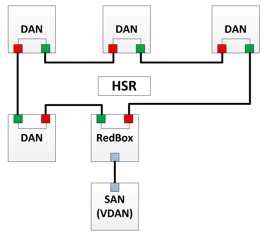
HSR network structure
The principle of operation of HSR is that all devices are combined into a ring and all messages, as well as in PRP, are duplicated. The device sends both frames through the ring: one copy is clockwise, the other is against. The receiver receives both copies, but processes only the first, and the second deletes. If something happens to any of the links, and one of the duplicate frames does not come, then the other is simply accepted. All HSR devices have two Ethernet interfaces — port A and port B.
In accordance with the HSR protocol, the following elements may exist in a network:
- SAN is a node that has only one Ethernet interface. Such a node can only be connected to the HSR network via the RedBox.
- A DAN is a node that can exchange data within an HSR ring (it can send / receive duplicate frames).
- RedBox - as well as in PRP RedBox allows you to connect a device that has one Ethernet interface to the HSR network. The device that is behind the RedBox is seen as a DAN for other devices. Such a node is called a virtual DAN or VDAN (Virtual DAN).
- QuadBox - HSR also introduces one new item - QuadBox. This device has four HSR ports. It allows you to combine two HSR-rings. In each ring, QuadBox performs the role of DAN and can transfer data from one ring to another.
QuadBox usage example
DAN structure
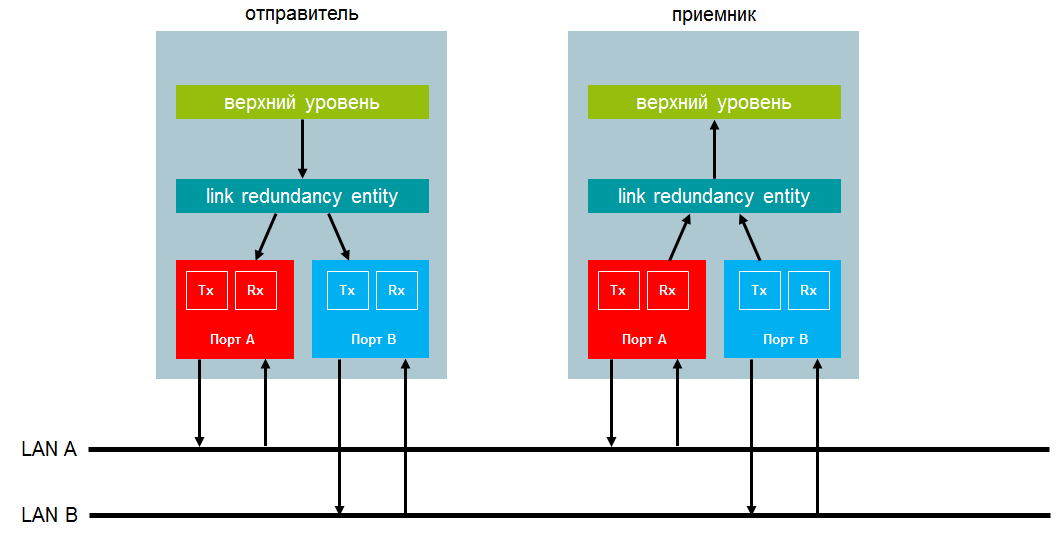
For PRP and for HSR, the DAN structure is similar. Each DAN has two interfaces operating in parallel and connected to the top level of one communication stack through the so-called LRE level - link redundancy entity. All redundancy functions are performed at this level.
Both DAN interfaces have the same MAC address and one IP address. This makes the reservation transparent to the top level. Especially important is the fact that it allows the use of ARP for DAN as well as for any unreserved node.
However, of course, there are some nuances in the DAN structure for PRP and for HSR.
PRP - DAN structure
When a frame is sent from the top level, LRE duplicates it and sends both packets through the ports almost simultaneously. Both frames are transmitted in parallel through two networks with different delays. In an ideal situation, they are delivered to the destination site with a minimum time difference. Upon receiving the receiver LRE, the first received frame is transmitted to the upper layer, and the second one is discarded.
LRE creates duplicate frames when sending and processes them when received. This layer, in relation to the upper layer, is a normal interface of a non-redundant network adapter. LRE performs two tasks: handling duplicate frames and managing backups. To implement the control, LRE adds a 32-bit redundancy control trailer (RCT) to each frame and deletes it when the frame is received.
Data transfer between two DAN to PRP
HSR - DAN structure
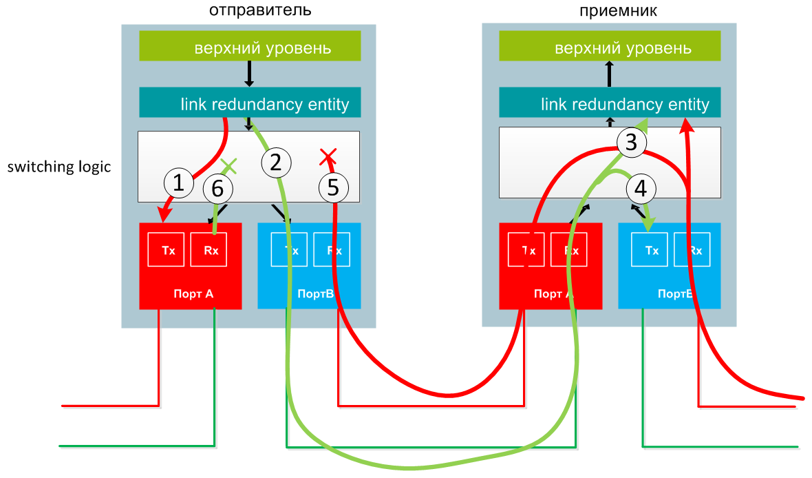
The frame sent from the top level is duplicated by the LRE layer, and the packets are sent through port A and port B almost simultaneously. (1 and 2 in the diagram).
When receiving a frame, the receiver transmits it to the LRE level, and also redirects to another port and transmits further in the ring. (3, 4).
If the frame arrives at the sender, then this frame is not transmitted further, but is destroyed (5, 6).
Both frames arrive at the LRE level, but the one that was sent faster is transmitted to the upper level, and the duplicate frame is dropped.
LRE adds a 48-bit HSR tag to each frame (akin to adding a VLAN tag) and deletes this tag when received.
Data transfer between two DANs in HSR
Interaction between SAN and DAN
A PRP SAN can be connected to any network — LAN A or LAN B, but such a node does not support redundancy features. Therefore, a SAN connected to one network will not be able to communicate with another similar node connected to the second network. For interaction with SAN, DAN generates special frames. This need is caused by the fact that a SAN in a normal frame from a redundant device must ignore the RCT, which is not possible, since the SAN cannot distinguish the RCT from the normal IEEE 802.3 data block. In turn, the DAN understands that it sends a frame to the SAN and does not add the RCT to the frame. It simply sends one frame from the top level to the interface to which the SAN is connected. In other words, if the DAN cannot determine what is communicating with another DAN, then it does not add the RCT to the frame.
In HSR, a SAN cannot be directly connected to the network. It can only be connected via RedBox.
DAN Modes
When working with duplicated frames received on both interfaces (if they are healthy), the DAN must be taken in one of the frames and the second discarded. PRP has two processing methods:
- Duplicate accept is a method in which both incoming frames are received and redirected to the upper level.
- Duplicate discard is the method by which the receiving node reads information from the RCT of the incoming frame in order to determine which frame to discard.
For HSR, consider the most popular modes U and X
Duplicate accept
DAN operating in this mode does not drop any of the frames during link level processing.
Frames are sent to LAN A and LAN B without RCT. The receiver LRE simply redirects both frames to the upper level, assuming that on further transmission duplicates will be destroyed (IEEE 802.1D clearly states that the upper level protocols must be able to handle duplicate frames).
For example, TCP and UDP protocols have a high level of resistance to duplicate frames.
This method is very simple to implement, but it has a serious drawback - it does not provide any network monitoring capabilities, since in no way monitored the correctness of the reception of both frames.
Duplicate discard in the link layer
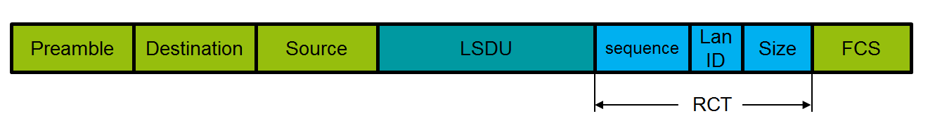
When using the second method, a field consisting of four octets - RCT (redundancy control trailer) is added to the frame. The trailer is added at the LRE level when the frame is received from the top level. RCT consists of the following parameters:
- 16-bit sequence number;
- 4-bit network identifier, 1010 (0xA) for LAN A and 1011 (0xB) for LAN B;
- 12-bit frame size.
Due to the addition of an RCT trailer to the frame, its size is larger than the maximum frame size specified in the IEEE 802.3-2005 standard. To transmit data within a network with a PRP, the equipment must be configured to transmit data in the size of 1496 octets. Because of this, not every switch is suitable for use on LAN A or LAN B.
RCT frame added
Each time a link layer sends a frame to a specific address, the sender increments the sequence number for the corresponding node and sends identical frames through both interfaces.
The receiving node shall determine duplicates based on information from the RCT.
Duplicate discard method algorithm
The receiver assumes that frames sent from any source operating under the PRP protocol are sent sequentially with an ever-increasing number. The sequence number that is expected for the next frame is stored in the variables ExpectedSeqA and respectively ExpectedSeqB.
Upon receipt, the sequence correctness can be checked by comparing the value of ExpectedSeqA (ExpectedSeqB) with the sequence number of the received frame stored in the variable currentSeq in the RCT. If the result is positive, the ExpectedSeq variable is set to one more than the currentSeq in order to be able to perform a correct check on this line.
Frame drop interval (drop window)
For both interfaces, there is a dynamic frame drop interval (sliding drop window) for paired sequence numbers. The upper boundary of this interval is ExpectedSeq (the next expected sequence number on this interface), excluding this value itself, and the lower boundary of this interval is startSeq (the smallest sequence number at which the duplicate frame is dropped with that sequence number).
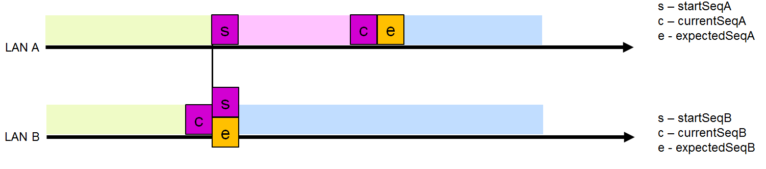
After checking the correctness of the sequence number, the receiver decides to discard this frame or not. Suppose that LAN A has a non-zero frame dropping interval (Figure 5). A frame from LAN B whose number lies in this interval will be dropped. All other frames from LAN B will be received and sent to the upper level.
By discarding the frame from LAN B, the size of the LAN A interval is reduced, since after receiving this frame, no frames with a lower number are expected on this interface. Accordingly, startSeqA is set to one more than currentSeqB. In this case, the size of the drop interval of the LAN B frame is reset to 0 (startSeqB = expectedSeqB), since it is obvious that LAN B frames are “behind” LAN A and no frames from LAN A should be dropped.
Reducing the LAN A interval after dropping a frame from LAN B
In the situation of Figure 7, when several frames from LAN A come in succession, but nothing comes from LAN B, they are accepted because their currentSeq is outside the drop interval of the LAN B frame and the LAN A interval is increased by one position. If frames from LAN A continue to arrive, and still nothing comes from LAN B, when the maximum interval size is reached, startSeqA also begins to increase by one.
When the received frame is outside the frame’s drop interval of another LAN, this frame is saved, and the interval size of this interface is set to 1, which means that only a frame from another LAN with the same sequence number will be dropped, while the drop window of another interface is set to 0, which means that no frame will be dropped (Fig. 7).
Frame from LAN B has not been dropped
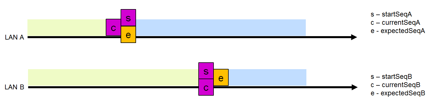
The most common situation is when both interfaces are synchronized and the size of both intervals is 0 (Fig.8), which means that the frame of the interface that comes first will be accepted and the interval of this interface will be increased to 1, which will allow you to drop the frame from another interface from same sequence number.
Synchronized LAN
Due to the presence of a LAN identifier in the RCT, duplicate frames differ by one bit (and have different checksums). The receiver checks the frame for the interface (i.e., checks that the frame with the identifier LAN A has arrived at interface A). The receiver will not discard this frame, since it may contain useful information in the data block, but in this case the counter cntWrongLanA or cntWrongLanB will be increased by one. Since such errors are not one-time errors (they are confused with LAN A and LAN B), the counter will increase constantly.
HSR traffic transmission on the data link layer
When transferring data within the HSR network, an HSR tag is added to each frame.
An HSR tag consists of the following parameters:
- 16-bit HSR Ethertype
- 4-bit direction indicator (path indicator)
- 12-bit frame size
- 16-bit sequence number
The sender inserts the same sequence numbers to the duplicate frames sent, and then increments the sequence number for each parcel sent from this node.
The receiver keeps track of the sequence numbers of all frames from each source from which it receives data (it distinguishes sources by MAC address). If frames come from different lines and have the same source and sequence number, one of them is received, and the second is discarded.
To control the network, on each device is a table of all nodes in the network from which it receives data. This allows you to detect the disappearance of nodes and errors on the bus.
The node determines the frame that it sent to the source and the sequence number.
HSR tag added frame
The HSR node never drops a frame that it has not previously received. The node defines almost all duplicated frames, but if there are not many of them, it does not delete them, i.e. the frame simply passes the entire ring and is destroyed on the sender.
In the standard, the algorithm for determining duplicate frames is not defined. As possible methods, hash tables, queues, and tracking of sequence numbers can be used.
U mode
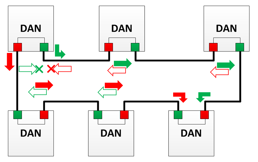
In this mode, the node that receives the frame destroys the duplicate and does not allow it to spread further. If the frame is still transmitted further, it is destroyed on the following nodes. This mode allows you to unload the ring from Unicast traffic.
In the diagram, red arrows indicate packets with HSR-tag sent from port “A” (hereinafter referred to as frame “A”).
Green arrows indicate packets with HSR-tag sent from port “B” (hereinafter referred to as frame “B”).
Empty arrows indicate dropped traffic, i.e. frames that would be transmitted during normal operation, but in this mode were dropped.
Cross indicates the removal of traffic from the ring (in any case).
X mode
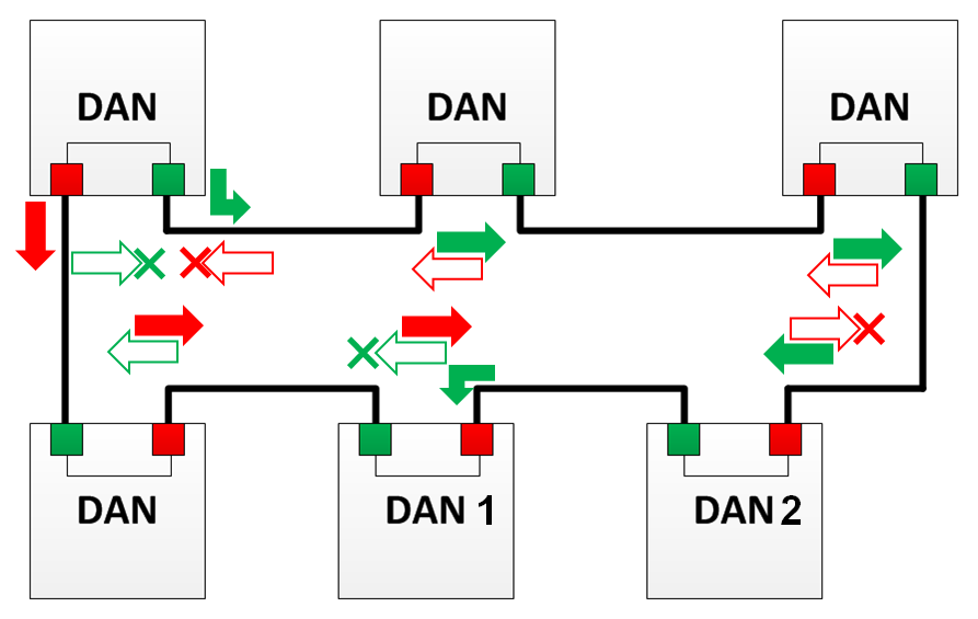
In this mode, the node does not transmit the frame further and discards it if such a frame was received from another direction.
For example, DAN 1 in the image will not transmit frame “B” further, since he has already received the frame “A”, and DAN 2 will not transmit further the frame “A”, since already received frame “B”.
If an error occurred somewhere in the algorithm and the frames were transmitted further, they will be dropped on the following nodes or on the node on which they were created.
X mode is not applicable for PTP messages and for transmission frame.
Network control
PRP
The receiver checks that all frames arrive consistently and correctly received on both channels. It supports error counters that can be read, for example, via SNMP.
All devices maintain node tables with which they exchange data. These tables contain information about the time when the last frame was sent or received from a specific node and other information related to the PRP protocol.
At the same time, these tables allow detecting connections in which it is necessary to synchronize sequence numbers, as well as detect broken sequences and missing nodes.
Diagnostics is based on the fact that each DAN periodically sends a diagnostic frame (supervision frame), which allows you to check the integrity of the network and the presence of nodes. At the same time, these frames allow you to check which devices act as DAN, determine their MAC addresses and in what mode they work - duplicate accept or duplicate discard.
HSR
Each node constantly checks all links.
Each node periodically sends a diagnostic frame (to both ports) containing node status information. This frame is received by all nodes, including the sender. When the sender receives its own diagnostic message, the integrity of the physical channel is checked.
The interval of sending a diagnostic frame is relatively large (several seconds), because it is not required to provide redundancy, but is needed only for diagnostic purposes.
All nodes are listed in the table of all partners that were found, and record the time when the node was last active, as well as all missing frames and frames sent not sequentially.
All topology changes that have occurred are also logged and all information can be obtained via SNMP.
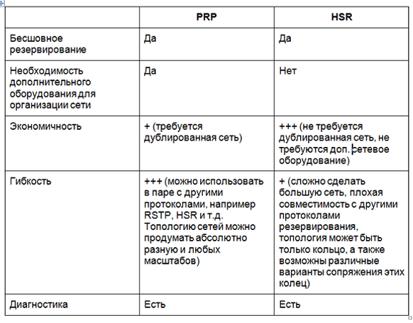
HSR and PRP: Pros and Cons
Conclusion
It cannot be said that one protocol is better than another - they are created a bit for different applications. Both HSR and PRP allow seamless network redundancy, but HSR allows for more cost-effective solutions. But such profitability entails difficulties, since HSR-based network is difficult to scale, and applications are not very flexible. Low flexibility is due to limited topology (ring, pairing rings), as well as poor protocol compatibility with other technologies. Therefore, HSR is better suited for backing up small systems and integrating into a large network. It is quite problematic to organize the reservation of the entire network based on HSR. PRP, in turn, is a more expensive solution, but it allows you to organize a fairly large-scale network, which you can later expand without problems, because This protocol makes it possible to conveniently integrate almost any technology and implement completely different topologies.
Find a solution
Source: https://habr.com/ru/post/443248/
All Articles