Three eyes hang on a pole, or the tale that ATtiny13 has five legs
KDPV "Oh, everything."
There is little chance that this longrid will become a life-giving source of wisdom to intellectuals, tempted in the secrets of fortune-telling on Carnot cards, and who have learned the hidden meaning of the Third Normal Form. But if for some reason you touched the arduino with your hands, a soldering iron gathers dust in the pantry, you understand why the battery has one plus, and C ++ has two, then truly magical and amazing wonders will not leave you indifferent. So, I have the pleasure of recommending to you the numbers of today's presentation of the traveling circus "Saman with Boxwood" :
- Adding RAM and ROM to ATtiny13!
- Artificial intelligence in the microprocessor - pro and contra, or sleeping beauty - well, is she not a fool?
- Or all the same dura lex sed lex?
- How to add legs in ATtiny13?
- A few words about the fifth dimension: how to cram in nevpihuemoe?
- Sawing in half non-devistenits with mixing the contents of the halves (with a guarantee of recovery).
- Room “Feeding the afflicted” (see earlier case of saturation of five thousand people with five barley loaves and two fish).
If at least one of the tricks is useful in the future to every twentieth reader, I will be satisfied, the article was written not in vain.
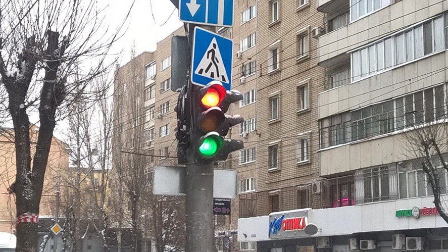
Traffic light first or Kaa takes the fight.
The story began, as in the classic pre-Christmas video entry, when the camera peeks through a frosty window into a small cozy room: a Christmas tree in tinsel, cotton and toys, the smell of tangerine and mulled wine, a warm shake of the shadows from a candlelight. On a large couch, She straightens the rug and gently presses her cheek against His shoulder, absently listening to enthusiastically gesturing angelic little girl ...
Those who have parental experience are well aware that at such a moment one can hear. I will explain to those who have not yet acquired such a skill - with a high degree of probability, parents are now dumbfounded with something like: “Dad! Us tomorrow! In kindergarten! It is necessary! Bring crafts to the contest of Christmas tree toys! And I want first place! ”.
It is necessary. Tomorrow. Us. Under the tree. The best.
The interview with the Customer involved shows the outlines of the TK: we need a traffic light. And so beautiful and glowing, like a real one. Already at this stage, the ranks of candidates in the project's GUI are dramatically thinning: the pope fails to substantiate the idea that the charming, soft, stitched from shreds or knitted or crocheted traffic light is an embodiment of the Customer’s dream: the traffic light should be lit - what is there to understand?
Night rolled over the country, and our work began to boil.
The material of the traffic light body is a toilet paper sleeve compressed so as to form a parallelepiped. The ten-ruble coin was encircled with a pencil, and then the holes for the lights of the signal light were cut out with a stationery knife (traumatic work is not trusted to children).
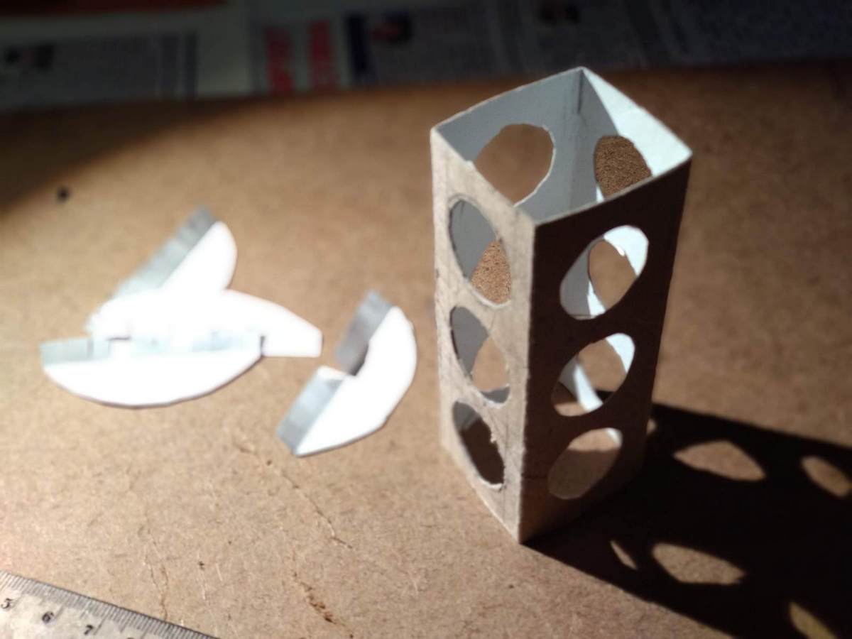
The top and bottom covers of the traffic lights are cut out of cardboard in place. Visors above the lamps on the made pattern were outlined on ordinary 80 gram paper and cut by hand.

Then they were glued to the PVA.
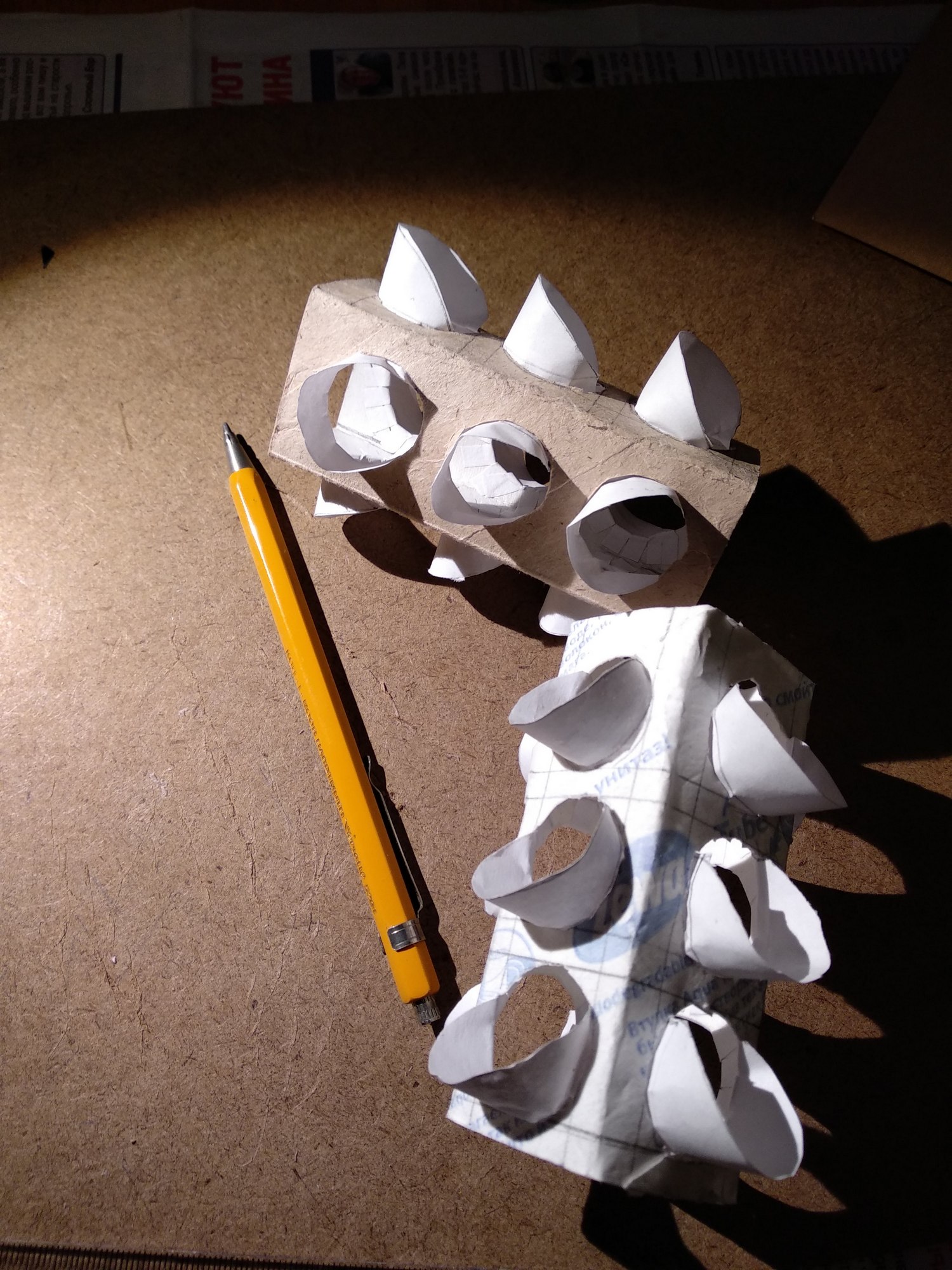
The assembled constructions were pulled out into the courtyard and painted with spray acrylic paints: generously silver, after slightly black on top.
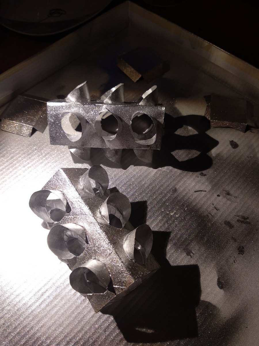
In case of damage at any stage, three copies were made at once. Light filters inside the most successful pasted three strips of colored paper - red, yellow and green.
It was decided to illuminate from the inside with a pair of superbright white LEDs from the generous bins of the motherland (SchZR). The cadets' toad flatly refused to give the Pope three more lithium tablet batteries from the presence of the SCHR, and the LEDs did not agree to light up one, stating that they were white and bright, and the voltage drop on them was from 2.8 to 3.9 volts. The maximum that was managed to bargain with the toad was for one AA battery, a ferrite ring from the choke of a burnt-out motherboard and the KT315 transistor. After thinking and googling, Dad had to accept the offer. And considering the number of playful pens in each group of the kindergarten, the idea with lithium batteries didn’t look particularly attractive.
The corpus of traffic lights on the battery with a tough smell of paint displaced the aromas of pine needles and tangerines, the father thoughtfully poked a soldering iron into the rosin, the children wound transformers for the blocking generators (duplication of copies), everything went according to plan ...
And no, "and all of a sudden" that evening did not happen: all the tricks when winding a transformer - immediately wind the maximum possible number of turns with folded wire. Do not confuse the anode and cathode of the LED, and the leads of the KT315 transistor and correctly connect the ends of the windings (or swap them if not lit) according to the circuit diagram. J1 - power switch from a computer jumper, derived later "on the roof" of a traffic light.
A completely simple scheme for producing alternating voltages with peaks of 3-7V from 1.5V of a G1 battery has long been widely known .
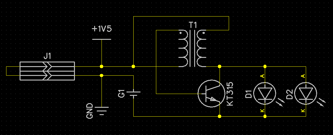
Physically, the concept was embodied like this:
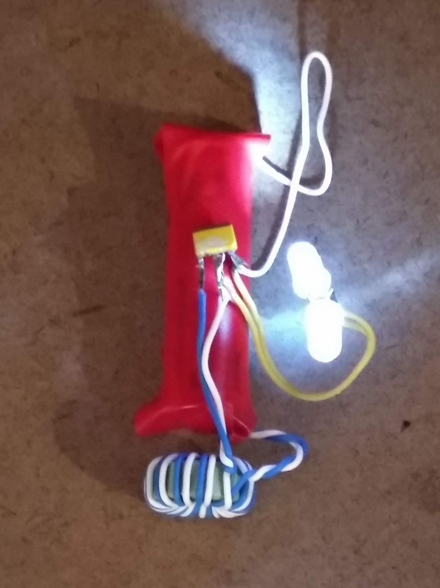
In the red tape - alkaline AA battery.
And the traffic light assembly - that's it.
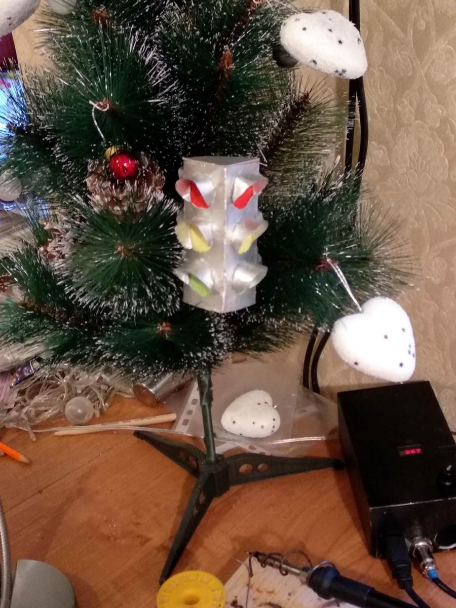
In the morning, the proud child dragged the product to the kindergarten, where the toy created a sensation and took center stage on the Christmas tree.

With the first place in the competition, however, did not work out - the deadline for submission of entries, as it turned out, several days had passed.
The houses remained two buildings on the windowsill and daddy's itchy dissatisfaction with the task “I want like a real traffic light.” And the thought was spinning, “is it possible to fit the complete solution, say in the 13th tinkle, that the toad in the SCHZR has been lying around for a long time? Will there be enough five legs, a kilobyte for the code and 64 bytes of RAM, and that, as ordered, like a real one”?
So all this was just a saying, a tale about the final solution of the traffic light issue ahead.
Traffic light second, like a real
Used tools, materials and documentation
Language / Framework : C / Arduino 1.6 / 1.8.
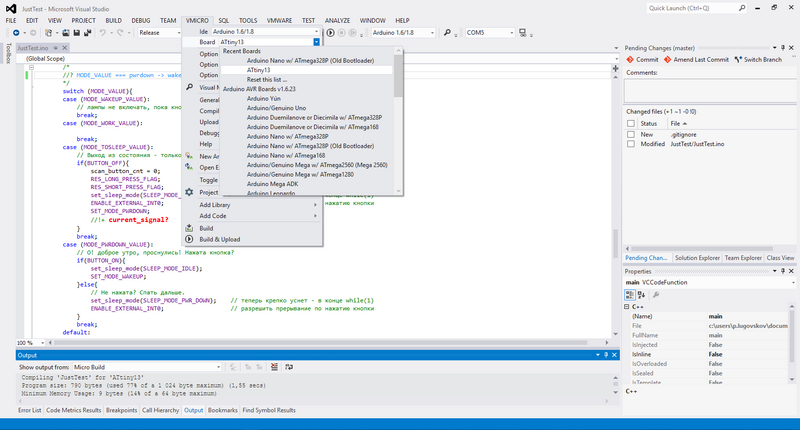
IDE : MS Visual Studio 2012 + Visual Micro plugin + git.
CAD : DipTrace.
HW : MK ATtiny13, Arduino Nano Clone on ATmega328, USB-UART on FT232R, china-noname USBISP programmer.
PP technology : LUT .
Tools : Soldering iron, glue gun, kitchen oven, knife, scissors, cutting pliers.
Materials : From “SCHZR” - 4 noname red, yellow, green output LEDs, SMD tantalum capacitor and a pair of resistors 0805 through 10k, half a dozen output 0.25W current limiting resistors MF-25, Chinese boost DC-DC 5V converter, aerosol cans with silver and black paint, A4 paper, polymer clay with a sale.
Sources and documents are available on Github under the MIT license, source code commits coincide with the firmware iterations described below, all mentioned paths to files are relative to the repository root.
Documentation :
./docs/ATtiny13A datasheet.pdf [Specification for Atmel ATtiny13A MK]
./docs/ATmega328 datasheet.pdf [Specification for Atmel ATmega328 MC]
./docs/AVR4027 - Tips and Tricks to Optimize Your C Code for AVR Microcontrollers]
./docs/AVR4013 - PicoPower basics.pdf [Notes on Energy Saving Modes]
From the Arduino IDE , like a blanket from a cloud. Their wizard is a Jesuit subtle mockery of everything that can be held by embed programmers. But Arduino, as an ecosystem, lived, lives and will live, and because of the ease of installing the environment on computers under different operating systems, and because they were the first to give the opportunity, without much expense to the hardwired programmer-debugger, using the cheap UART and proprietary bootloader development in a fairly serious stuffing MK. And then there's Uncle Liao, ready to sell a fistful of clones for the price of one original. The fact that in the senior atmega you can debug the logic and the work of the program, and then with minimal changes to transfer to the same tyinki - this is also an Argument.
I am accustomed to working comfortably in MS VisualStudio , there is no extra space for AtmelStudio or WinAVR and I don’t want to search, they don’t carry the ultimate amenities without a hardware debugger . About the VisualMicro plugin, which adds support for Arduino in MS VisualStudio , it was already quite detailed and well-written on Habré.
Focus "Arduino on ATtiny13" on Habré was also considered a long time and repeatedly .
In short, in the installed installation of the Arduino environment, add the MicroCore module, after which it becomes possible to select the ATKinyK MK target cards.
Git - no alternative for any, even the most domestic projects. The habit is simple but correct: when starting work on any program, just type "git init" in the directory on the command line. The support of comets in the local repository built into MS Visual Studio will save time and nerves more than once.
DipTrace, as CAD for circuitry and PCB - convenient, domestic, schematics and wiring is user-friendly, easy to add custom components (CVD, contacts), if desired, the PCB with components can be twisted in 3D, high-quality help and tutorials in the kit. In addition, I am impressed by their licensing policy: the restrictions of the Non-profit standard license free for Russia, Ukraine, and the Republic of Belarus (1000 pins, 4 signal layers) are enough for home crafts in 99% of cases.
I didn’t manage to get Arduino Nano to make money normally, like a programmer for tinky, but if there is a USB ISP programmer, the problem can be solved easily. Quickly sketched command files for compilation / firmware - in the ./gcc directory in the project.
The .ino file (and actually it is C / C ++) is unmistakably compiled in the studio "under arduino under ATtiny13", simply served by the parameter of this batch file on the command line:
>"./gcc/0_MAKE & upload.cmd" MyArduinoFile.ino If at this moment an ISP programmer is plugged in, and the MK is attached to it, then both compilation and firmware will run.
>"./gcc/0_MAKE & asm.cmd" MyArduinoFile.ino As the name implies, having compiled it will create an assembler listing of the firmware — it can be very useful, even if the assembler for AVR is not the strongest side of the skills. Important : If you want to use command files, you will need to change inside the path, they are absolute .
Soul traffic light
Upgrade ROM & RAM for Arduino for ATtiny13
The skeleton of the Arduino programs (sequentially setup () {...}; loop () {...};) invisibly for the arduinschik when compiled actually "wraps" into the classic C-shnu int main () {setup (); loop ();}, slightly gaining weight due to overhead by Arduino.
uint8_t cnt; void setup() { cnt=0; } void loop() { cnt++; } //Program size: 164 bytes (used 16% of a 1 024 byte maximum) (0,57 secs) //Minimum Memory Usage: 5 bytes (8% of a 64 byte maximum) Actually the exact same thing, but without calling functions on a simple C:
uint8_t cnt; int main(){ cnt=0; // < setup() while(1){ cnt++; // < loop() } } //Program size: 60 bytes (used 6% of a 1 024 byte maximum) (1,23 secs) //Minimum Memory Usage: 1 bytes (2% of a 64 byte maximum) In addition to reducing from 16% to 6% of the required program memory, note that 6% of free random access memory for variables was added. And still, the call of any function until its completion invisibly consumes memory at least at the return address in the stack, and the stack is also part of the 64 byte of the physical physically present.
Sleeping Beauty Intellect
Obligatory sign of intelligence, of course, is laziness: a rational being will not begin to perform useless work. A non-intelligent processor will scroll through an infinite loop over and over again, it is useless to convert energy into heat, and only occasionally, when the external conditions change, do the work of changing the state. A smarter processor, in contrast, only works when external conditions have changed. In order to improve the integration index of the mind on the planet Dirt, we transfer the tinsel to the next stage of intellectual development: our CPU will sleep most of the time, waking up and working only when necessary. His job is to increment a global variable that stores a time value every N time units. During sleep without the participation of the “brain” -CPU, the timer will continue to operate, increasing in sleep by one every (9.6 MHz cycles per second / divider value of the timer 1024 = 9370 Hz, so many times per second the timer is incremented) 1/9370 = 0.0001067 seconds . But the CPU will wake up only when the 8-bit timer overflows. And having woken up, first of all it is thrown, as at night, into the toilet, into the procedure of handling the "timer overflow" event. And after that, he will run on the program further, starting from the place where he fell asleep, until he reaches the place in an endless loop with the "sleep" command. He will have such awakenings 37 times in a second (256 x 0.0001067 = 0.027315; 0.027315 x 37 = 1.01065 ~ = 1s).
Program skeleton change: we set the clocking and the timer-counter divider (HW block, incrementing its value every 1024 cycles), when 8 bits overflow this counter, the overflow interrupt handler is started, then control is transferred to the next line of the program after the one in which it fell asleep.
Important : the globalTimer variable is defined as volatile, which means that it changes at a completely unpredictable and unknown time, as a result, before any use of it, the CPU must first read its current value from memory, even if the actions with it were in the previous line of the program .
#include <avr/io.h> // IDE - #include <avr/sleep.h> // , #include <avr/interrupt.h> // volatile uint16_t globalTimer; // 64 // - globalTimer 1/37 ISR(TIM0_OVF_vect){ globalTimer++; // . , , while(1) . } int main() { // " -". set_sleep_mode(SLEEP_MODE_IDLE); // - . sleep_enable(); // TCCR0B = _BV(CS02) | _BV(CS00); // 0 - clock frequency / 1024 TIMSK0 |= _BV(TOIE0); // overflow interrupt sei(); // while(1){ //......... sleep_cpu(); // - . } } //Program size: 128 bytes (used 13% of a 1 024 byte maximum) (0,86 secs) //Minimum Memory Usage: 2 bytes (3% of a 64 byte maximum) "The cat has 4 legs: entrance, exit, earth and food" (c) pitiful student song
A small digression explaining what strange abbreviations appeared in the listing.
In microprocessors, the control of peripheral blocks , in the same way as the CPU control, is done by writing / reading values to / from certain addresses of the memory space. Using the example of a GPIO peripheral module.
The signal level and type of foot in the Arduino are very easy to set: first, for the Arduino board pin pin number we turn on the input mode (or output):
pinMode(pin_number, OUTPUT); // INPUT - And then either expose the high / low value on the leg to exit, or read - what voltage comes to foot for entry.
Value = digitalRead(pin_input_number); //Value - HIGH LOW (1 0) digitalWrite(pin_outpit_number, Value); // pin_outpit_number - HIGH LOW To "simplify" the lives of users, the creators of the Wiring language went for some substitution using numbers printed on the Arduino board (white on the board or in pale fuchsia rectangles) instead of the foot numbers of the microcircuit (white on gray) or port accessories numbers (black on yellow ) (which is more logical and correct).
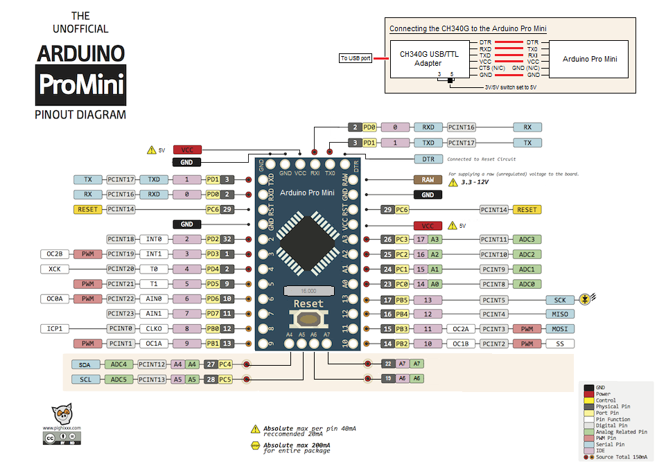
So the pin number of the Arduino 7 is equivalent to the pin number 11 or PD7 - the seventh bit of port D.
All the constructions of digitalRead, digitalWrite, pinMode, etc., all the same, when compiling, come to the installation of operating modes and values in numbering close to the processor, alas, adding to each Wiring-function just an awesome bunch of additional actions, making the code harder and slow down the work order.
Management of leg states - it is even easier than what arduin teaches us. Better than DIHALT to explain the modes of operation and the installation of ports, I’m unlikely to succeed.
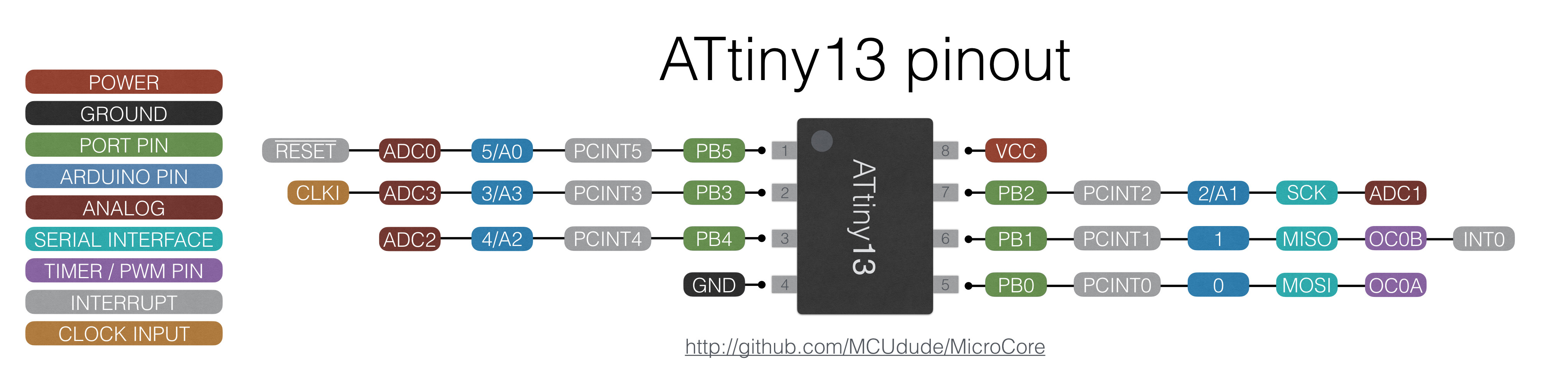
From inside the processor, general purpose input / output ( GPIO ) legs are seen grouped by logical ports, for 8-bit processors - a maximum of 8 legs per port. In a low-legged pairing, it is not enough that only 6 legs can be physically involved (Fig. ATtiny13 pinout, white on green), from PB0 to PB6, and also using PB6 - the possibility of programming MK without a special high-voltage programmer disappears. Any general-purpose I / O port is controlled by three registers: (for example, a port with the name "B") DDRB , PINB and PORTB . The I / O Control Register is a memory cell with which you can assign values or read them. Legend PB0, PB1, PB2, PB3, PB4, PB5 - matching the legs to the bytes of the ports in the port registers B. When added to the beginning of the program, include #include <avr / io.h> (or even iotn13.h for tyinki), these definitions will get the numbers bits (PB0 will be 0, ..., PB5 - 5) in bytes of register values in the IDE, and it will be possible to compile without involving the Arduino framework.
Important : if the program does not access the peripherals registers, this is the same as writing zero values to these registers. As a rule, the default values leave the peripherals block in the off state, but, for example, the zeros in the DDRx GPIO determine that the legs are inputs. And at the same time, zero in PORTx - the internal tightening is NOT included, the potential is “somewhere between zero and one”, the legs are sensitive to which direction they will bow - up or down, what to write in PINx. The electromagnetic field from the wiring is enough for them to change the state between 0 and 1 50 times a second. And the processor will spend electricity for each switch, meaningless and not obvious to a programmer .
on PB2 I want to bring HIGH, + 5V, on PB3, LOW, 0V, and from PB0 on the contrary, read what is the logical voltage level on it.
DDRB assign the value of the number for which the PB0 bit, the number zero (leftmost) = 0 (PB0 is defined as an input), the second and third bits = 1 (PB2, PB3 - outputs), i.e. in the binary notation, the number xxxx11x0, where x is anything, even 1, at least 0, is not specified in the conditions.
DDRB = 12; // 000001100 - 12 // (!) // pinMode(). To set the setpoints on the pins - assign the PORTB number, whose second bit = 1 (PB2 to HIGH), and the third to zero (PB3 to LOW), the rest is not important, xxxxx01xx
PORTB = 8; //(dec)8 === (bin)000001000 // - . To read the level from the legs, the port has the third and last control register of PINB, there is a number in it, the values of which bits are the logical voltage levels of the corresponding legs.
Everything would be fine, but converting from binary numbers to decimal and back is some confusion.
How to set bit number 3 (PB3) to one: just put 1 at zero, and move it 3 times to the left.
3 << 00000001 === PB3 << 1 // Result - 00001000
For a very easy life, there is a macro, _BV (x), which when compiled is replaced by (x << 1), so _BV (PB3) - sets the third bit to 1.
Recording _BV (PB3) | _BV (PB2) at compilation will turn into the number 00001100 (| - logical bitwise OR).
Important : the macro expands to a number already at compilation, there will be no bit actions in the firmware, but the resulting constant will be used .
PORTB |= _BV(PB3) | _BV(PB2); // 2 3 == 1, PB2 PB3 HIGH, PORTB For setting 0, the logical OR will not work, so just move the unit to the right place in the byte, and then invert the byte. The resulting value will have 0 at the required place and 1 at the rest. Adding according to the logical AND with the register value, those bits, where 1 of the current register values will not change, and where 0 - the corresponding ones will be reset to 0.
PORTB &= ~(_BV(PB3) | _BV(PB2)); // PORTB 2 3 - , LOW, . In the listing above, another HW block is initialized, timer-counter 0, Timer0. It is more complicated than GPIO, it is controlled not by three, but by seven registers, their values are described in detail in datasheet ATtiny13, if someone wants to read more in Russian, you can see the bit assignments in Ilya Ananev's blog in a very similar timer-counter 0 in the senior ATmega328.
I change only those registers whose functionality runs what I need.
TCCR0B = _BV(CS02) | _BV(CS00); // CS02 CS00 1 - 0 = clock frequency / 1024 TIMSK0 |= _BV(TOIE0); // TOIE0 1 - TIM0_OVF // TIMSK0 = _BV(TOIE0); GOST or law is the law.
, . , , . - , , , (!) .
, . " 27.02.13 " 7 52289-2004 , .
( ): , , , , , .
"* " " 2 , — 3 .
3 1 /.*"
, ( , / — PERIOD_0 PERIOD_4, — ).
#define ONE_SECOND 37 // 1 #define QT_SECOND 9 // #define PERIOD_FLASH_GREEN QT_SECOND // ( ) - #define PERIOD_FLASH_YELLOW ONE_SECOND * 1 // - - // --- #define PERIOD_0 ONE_SECOND * 10 //RGRG 0. --- (10 ) #define PERIOD_1 ONE_SECOND * 3 //R g R g 1. --- (3 ) #define PERIOD_2 ONE_SECOND * 1 //RYRY 2. --- (1 ) #define PERIOD_3 ONE_SECOND * 2 //RY Y RY Y 3. + --- (2 ) #define PERIOD_4 ONE_SECOND * 7 //GRGR 4. --- (7 ) #define PERIOD_5 ONE_SECOND * 3 //g R g R 5. --- (3 ) #define PERIOD_6 ONE_SECOND * 1 //YRYR 6. --- (1 ) #define PERIOD_7 ONE_SECOND * 2 //Y RY Y RY 7. --- + (2 ) , , .
typedef struct{ const uint8_t ddr_val_0; // DDRB value - const uint8_t port_val_0; // PORTB value - const uint8_t ddr_val_1; // DDRB value - "", const uint8_t port_val_1; // PORTB value - const uint16_t flash_period; // period of flashing - _val_1 _val_0 const uint16_t signal_period; // period of this lighting state }lightSignalization; // , _0 _1 - , flash_long - // flash_period == 0, , _val_0. // signal_period == 0, . , 128 — , .
ATtiny13 ( ?) -
, , - - , : 6 . - denvo " ? RESET " 5- , , , , - .
- : --, .. , 7 .
— , , , 8, ?
, -, "reset", PB6, .
, ? , , , . , , , , , .
, , 8 9 - , 8 — . , -, , , , .
— .
: — . .
:
1 PORTB |= _BV(GREEN_PIN) — ( ) , 0 .. PORTB &= ~(_BV(GREEN_PIN)) — ( ).
, , ?
(DDRB |= _BV(GREEN_PIN)) , DDRB &= ~(_BV(GREEN_PIN)), GREEN_PIN Hi-Z . (2.2 * 4) 5, .
.
— .. , , .
, . , — , 37/2=18 , , . But:
) , , , , ;
) — , " " 4 ;
) , 4 ( PERIOD_2->PERIOD_3 PERIOD_6->PERIOD_7);
) 4 .
.
// PINB === 0 0 0 gr y0 btt y1 #define RED_PIN PB3 // OUT: 1 - "-" , 0 - "-" , IN - , , (!) #define YELLOW0_PIN PB2 // OUT: 1 - "-" #define YELLOW1_PIN PB0 // OUT: 1 - "-" #define GREEN_PIN PB4 // OUT: 1 - "-" , 0 - "-" , IN - , , (!) #define RED _BV(RED_PIN) // _BV - (), 1<<VALUE #define YELL0 _BV(YELLOW0_PIN) // - #define YELL1 _BV(YELLOW1_PIN) #define GREEN _BV(GREEN_PIN) // - ( 0 - -) DDRB.GreenPin=1 — . , , — , .
#define BUTTON_PIN PB1 #define BUTTON_ON !(PINB & _BV(BUTTON_PIN)) //( (PINB & _BV(BUTTON_PIN)) == 0) // " " - LOW #define BUTTON_OFF (PINB & _BV(BUTTON_PIN)) // " " - HIGH, ( ) , , n ( ) n(n−1) = n²−n . 4 12 , . « , » « , » .
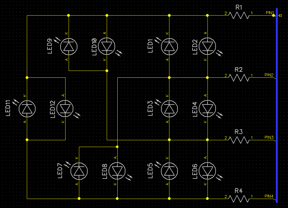
*** — , DDRx|PORTx, , .. . — , , .
.***
: ?
lightSignalization. lightSignalization . 0 7 , 8 — , 9 — , "" . , 0 7, . , , . 3 ( 0 7) 8 -- . if- , . , .
lightSignalization traffic_signals[] = {// // {DDRB0, PORTB0, DDRB_when_flashingif, PORTB_when_flasingif (if flashing), continous of half-period flashing, continous curr mode runing} {RED|GREEN, RED, 0, 0, 0, PERIOD_0}, // RGRG {RED, RED, RED|GREEN, RED, QT_SECOND, PERIOD_1}, // R g R g - flash east green {RED|YELL1, RED|YELL1, 0, 0, 0, PERIOD_2 }, // R Y1 R Y1 {RED|YELL0|YELL1, RED|YELL0|YELL1, 0, 0, 0, PERIOD_3 }, // RY0 Y1 RY0 Y1 {RED|GREEN, GREEN, 0, 0, 0, PERIOD_4}, // GRGR {RED|GREEN, GREEN, RED, 0, QT_SECOND, PERIOD_5 }, // g R g R - flash nord green {RED|YELL0, YELL0, 0, 0, 0, PERIOD_6}, // Y0 R Y0 R {RED|YELL0|YELL1, YELL0|YELL1, 0, 0, 0, PERIOD_7 }, // Y0 RY1 Y0 RY1 {YELL0|YELL1, YELL0|YELL1, YELL0|YELL1, 0, ONE_SECOND, 0}, // y0 y1 y0 y1 - flash yellows lights {0, 0, 0, 0, 0, 0} // traffic lights off, DDR in, Hi-Z }; // lightSignalization traffic_signals[] #define LIGHT_NUM_YELLOW_FLASH 8 // - - flash yellows lights #define LIGHT_NUM_STD_START 0 // #define LIGHT_NUM_LIGHTS_OFF 9 // - - traffic lights off lightSignalization 8 . .. traffic_signals[] 10 80 (, 64 , 2 ). , .
, , , — ROM, , RAM , .
-
const lightSignalization traffic_signals[] PROGMEM= {... ,
<avr/pgmspace.h> pgm_read_byte_near() pgm_read_word_near() char shortint .
3 .
, .
traffic_signals[] — LIGHT_NUM_LIGHTS_OFF
{0, 0, 0, 0, 0, 0} // traffic lights off
— lightSignalization , — , lightSignalization.signal_period==0 (.. ), lightSignalization.flash_period==0, .. ., .
traffic_signals[] — LIGHT_NUM_YELLOW_FLASH
{YELL0|YELL1, YELL0|YELL1, YELL0|YELL1, 0, ONE_SECOND, 0}, // y0 y1 y0 y1 — flash yellows lights
: lightSignalization.signal_period==0. lightSignalization.flash_period=ONE_SECOND, :DDRB = YELL0|YELL1; // YELL0, YELL1 - PORTB = YELL0|YELL1; // YELL0, YELL1 = HIGH -and
DDRB = YELL0|YELL1; // // YELL0, YELL1 - PORTB = 0; // YELL0, YELL1 = LOW -, --.
, .
traffic_signals[] — LIGHT_NUM_STD_START
{RED|GREEN, RED, 0, 0, 0, PERIOD_0}, // RGRG
: lightSignalization.flash_period==0.
DDRB = RED|GREEN; //RED GREEN — , .
PORTB = RED; // RED — HIGH (- )
// GREEN — LOW ( , - — )
lightSignalization.signal_period==PERIOD_0, .
current_signal. 2 — , lightSignalization.
uint8_t current_signal; // 1 , traffic_signals uint16_t tl_flash_end; // 2 ( !0), uint16_t tl_signal_end; // 2 ( !0) tl_signal_end != 0, globalTimer>tl_signal_end current_signal. 0 current_signal, 3, .
current_signal = current_signal & B00000111;
current_signal &= LIGHT_NUM_STD_MASK ; //current_signal & B00000111; current_signal , 0 7.
globalTimer — .
#include <limits.h> // USHRT_MAX #include <avr/sleep.h> // , #include <avr/interrupt.h> // #include <avr/pgmspace.h> // #define ONE_SECOND 37 // 1 #define QT_SECOND 9 // #define MAX_GLOBAL_TIMER_VALUE (USHRT_MAX / 2) // uint16_t globalTimer - . 65535 /2 // , MAX_GLOBAL_TIMER_VALUE - 1 #define PERIOD_FLASH_GREEN QT_SECOND // ( ) - #define PERIOD_FLASH_YELLOW ONE_SECOND * 1 // - - // --- #define PERIOD_0 ONE_SECOND * 10 //RGRG 0. --- (15 ) #define PERIOD_1 ONE_SECOND * 3 //R g R g 1. --- (3 ) #define PERIOD_2 ONE_SECOND * 1 //RYRY 2. --- (1 ) #define PERIOD_3 ONE_SECOND * 2 //RY Y RY Y 3. + --- (2 ) #define PERIOD_4 ONE_SECOND * 7 //GRGR 4. --- (10 ) #define PERIOD_5 ONE_SECOND * 3 //g R g R 5. --- (3 ) #define PERIOD_6 ONE_SECOND * 1 //YRYR 6. --- (1 ) #define PERIOD_7 ONE_SECOND * 2 //Y RY Y RY 7. --- + (2 ) typedef struct{ const uint8_t ddr_val_0; // DDRB value const uint8_t port_val_0; // PORTB value const uint8_t ddr_val_1; // DDRB value const uint8_t port_val_1; // PORTB value const uint16_t flash_period; // period of flashing - _val_1 _val_0 const uint16_t signal_period; // period of this lighting state }lightSignalization; // , _0 _1 - , flash_long - // (PINS === 0 0 0 gr y0 btt y1): // "" #define BUTTON PB1 #define RED_PIN PB3 // OUT: 1 - "-" , 0 - "-" , IN - , , (!) #define YELLOW0_PIN PB2 // OUT: 1 - "-" #define YELLOW1_PIN PB0 // OUT: 1 - "-" #define GREEN_PIN PB4 // OUT: 1 - "-" , 0 - "-" , IN - , , (!) #define BUTTON_ON !(PINB & _BV(BUTTON)) //( (PINB & _BV(BUTTON)) == 0) // " " #define BUTTON_OFF (PINB & _BV(BUTTON)) // ~(PINB & _BV(BUTTON)) -\\- " " #define RED _BV(RED_PIN) // _BV - (), 1<<VALUE #define YELL0 _BV(YELLOW0_PIN) // #define YELL1 _BV(YELLOW1_PIN) #define GREEN _BV(GREEN_PIN) // lightSignalization traffic_signals[] #define LIGHT_NUM_YELLOW_FLASH 8 // - - flash yellows lights #define LIGHT_NUM_STD_START 0 // #define LIGHT_NUM_LIGHTS_OFF 9 // - - traffic lights off #define LIGHT_NUM_STD_MASK 7 // ___++ &LIGHT_NUM_STD_MASK - 0 7 //.................................... // const lightSignalization traffic_signals[] PROGMEM= { // , , -, PINS === 0 0 0 gr y0 btt y1 // {DDRB0, PORTB0, DDRB_flashing, PORTB_flasinf (if flashing), continuous of half-period flashing, continuous id mode running} {RED|GREEN, RED, 0, 0, 0, PERIOD_0}, // RGRG {RED, RED, RED|GREEN, RED, QT_SECOND, PERIOD_1}, // R g R g - flash east green {RED|YELL1, RED|YELL1, 0, 0, 0, PERIOD_2 }, // R Y1 R Y1 {RED|YELL0|YELL1, RED|YELL0|YELL1, 0, 0, 0, PERIOD_3 }, // RY0 Y1 RY0 Y1 {RED|GREEN, GREEN, 0, 0, 0, PERIOD_4}, // GRGR {RED|GREEN, GREEN, RED, 0, QT_SECOND, PERIOD_5 }, // g R g R - flash nord green {RED|YELL0, YELL0, 0, 0, 0, PERIOD_6}, // Y0 R Y0 R {RED|YELL0|YELL1, YELL0|YELL1, 0, 0, 0, PERIOD_7 }, // Y0 RY1 Y0 RY1 {YELL0|YELL1, YELL0|YELL1, YELL0|YELL1, 0, ONE_SECOND, 0}, // y0 y1 y0 y1 - flash yellows lights {0, 0, 0, 0, 0, 0} // traffic lights off, }; volatile uint16_t globalTimer; // 64 uint8_t current_signal; // 1 , traffic_signals uint16_t tl_flash_end; // 2 ( !0), uint16_t tl_signal_end; // 2 ( !0) //.................................... void setPeriods(uint8_t num, bool set_both_flash_and_signal); // tl_flash_end, tl_signal_end void setPorts(uint8_t num, bool use_main_values); // //.................................... // // - globalTimer 1/37 ISR(TIM0_OVF_vect){ globalTimer++; // . , while(1) . } int main() { // bool use_main_values = true; // lightSignalization._val_0 (1) lightSignalization._val_1 (0)? - current_signal = LIGHT_NUM_STD_START; // . . // " -". set_sleep_mode(SLEEP_MODE_IDLE); // - . sleep_enable(); // TCCR0B = _BV(CS02) | _BV(CS00); // 0 - clock frequency / 1024 TIMSK0 |= _BV(TOIE0); // overflow interrupt sei(); // while(1){ // ? if(globalTimer > MAX_GLOBAL_TIMER_VALUE){ globalTimer -= MAX_GLOBAL_TIMER_VALUE; // // if(tl_flash_end){ tl_flash_end -= MAX_GLOBAL_TIMER_VALUE; // , } if(tl_signal_end){ tl_signal_end -= MAX_GLOBAL_TIMER_VALUE; // // , } // setPeriods(currentMode, false); // 12 , tl_.._end , } // (tl_flash_end !=0 ) if(tl_flash_end){ // if(globalTimer > tl_flash_end){ use_main_values = !use_main_values; // !use_main_values - )) setPorts(current_signal, use_main_values); // setPeriods(current_signal, false); // , } } // - operating_std - -- if(tl_signal_end){ // (use_main_values - - ) if((globalTimer > tl_signal_end) && use_main_values){ current_signal ++; // current_signal &= LIGHT_NUM_STD_MASK; // 3-, 0 7 use_main_values = true; // - setPorts(current_signal, use_main_values); // setPeriods(current_signal, true); // } } sleep_cpu(); // - . } } // void setPorts(uint8_t num, bool use_main_values){ uint8_t val; DDRB = 0; PORTB = 0; // () - ddr_val_0, else = ddr_val_1 // val = (use_main_values) ? pgm_read_byte_near(&(traffic_signals[num].ddr_val_0)) // : pgm_read_byte_near(&(traffic_signals[num].ddr_val_1)); // , , , , , 14 (!!!) . val = pgm_read_byte_near(&(traffic_signals[num].ddr_val_0)+( (use_main_values) ? 0 : 2) ); val &= ~_BV(BUTTON); // - DDRB = val; // val = (use_main_values) ? pgm_read_byte_near(&(traffic_signals[num].port_val_0)) : pgm_read_byte_near(&(traffic_signals[num].port_val_1)); val|= _BV(BUTTON); // - - PORTB = val; // } // ( void setPeriods(uint8_t num, bool set_both_flash_and_signal){ // tl_flash_end = pgm_read_word_near (&(traffic_signals[num].flash_period)); // tl_flash_end = (tl_flash_end)? tl_flash_end + globalTimer : 0; // - //if(tl_flash_end){ tl_flash_end += globalTimer; } <- 8 // - if(set_both_flash_and_signal){ tl_signal_end = pgm_read_word_near(&(traffic_signals[num].signal_period)); tl_signal_end = (tl_signal_end)? tl_signal_end + globalTimer : 0; // , } } //Program size: 610 bytes (used 60% of a 1 024 byte maximum) (0,58 secs) //Minimum Memory Usage: 7 bytes (11% of a 64 byte maximum) , . — btn_cnt ( ), ( ) .
#define PERIOD_PRESS_BUTTON_SHORT QT_SECOND // - #define PERIOD_PRESS_BUTTON_LONG QT_SECOND*6 // - / uint8_t scan_button_cnt; // // if(BUTTON_ON){ if(scan_button_cnt<USHRT_MAX){ scan_button_cnt++; // 1/37 } if(scan_button_cnt > PERIOD_PRESS_BUTTON_SHORT){ // , } if(scan_button_cnt > PERIOD_PRESS_BUTTON_LONG){ // } } — .

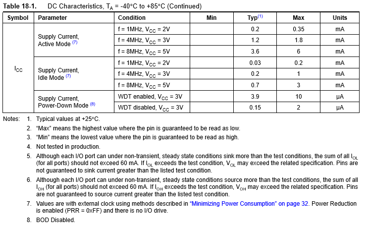
SLEEP_MODE_IDLE ( CPU), PwrDown SLEEP_MODE_PWR_DOWN — watchdog INT0, , — INT0.
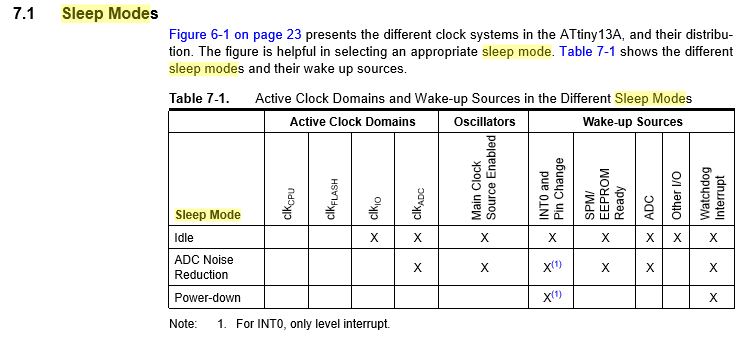
. 7.Power management and sleep modes ATtiny13 , 5-10 , .
8- , — 2 .
// uint8_t f_button_state_flags; // // MODES: wakeup 11 -> work 00 -> tosleep 01 -> pwrdown 11 -> wakeup 11 #define MODE_LBIT 0 #define MODE_HBIT 1 #define FORCE_SET_NEW_SIGNAL_BIT 2 // current_signal // 3 #define LIGHT_SIGNAL_ALT_MODE_BIT 4 // =0 (--) =1 ( ) #define USE_FIRST_VALUES_LIGHT_BIT 5 // - lightSignalization #define SHORT_PRESS_FLAG_BIT 6 // , 1 #define LONG_PRESS_FLAG_BIT 7 // , 1 , — , — CPU . , if-.
#include <limits.h> // USHRT_MAX #include <avr/io.h> // IDE #include <avr/sleep.h> // , #include <avr/interrupt.h> // #include <avr/pgmspace.h> // #ifdef GIMSK // ATtiny13 - #define F_CPU 9600000UL // , #define ONE_SECOND 37 // 1 #define QT_SECOND 9 // // GIMSK &= ~_BV(INT0); - INT0 #define DISABLE_EXTERNAL_INT0 GIMSK &= ~(_BV(INT0)); GIFR &= ~(_BV(INTF0)) //EIMSK/EIFR //GIMSK |= _BV(INT0) - INT0 #define ENABLE_EXTERNAL_INT0 GIMSK |= _BV(INT0) ; GIFR &= ~(_BV(INTF0)) #else // 328 - #define F_CPU 16000000UL #define ONE_SECOND 64 // 1 - . #define QT_SECOND 16 // // 328 INT0 - PD2... , (, ), #define DISABLE_EXTERNAL_INT0 EIMSK &= ~(_BV(INT0)); EIFR &= ~(_BV(INTF0)) // , - EICRA - ISC00-ISC01 == 00, lo level, EIMSK - INT0, EIFR-INTF0 #define ENABLE_EXTERNAL_INT0 EIMSK |= _BV(INT0) ; EIFR &= ~(_BV(INTF0)) #endif #define MAX_GLOBAL_TIMER_VALUE (USHRT_MAX / 2) // uint16_t globalTimer - . 65535 /2 // , MAX_GLOBAL_TIMER_VALUE - 1 #define PERIOD_PRESS_BUTTON_SHORT QT_SECOND/2 // ( - ) - #define PERIOD_PRESS_BUTTON_LONG QT_SECOND*4 // - / #define PERIOD_FLASH_GREEN QT_SECOND // ( ) - #define PERIOD_FLASH_YELLOW ONE_SECOND * 1 // - - // --- #define PERIOD_0 ONE_SECOND * 5 // RGRG 0. --- (5 ) #define PERIOD_1 ONE_SECOND * 3 //R g R g 1. --- (3 ) #define PERIOD_2 ONE_SECOND * 1 //RYRY 2. --- (1 ) #define PERIOD_3 ONE_SECOND * 2 //RY Y RY Y 3. + --- (2 ) #define PERIOD_4 ONE_SECOND * 7 // GRGR 4. --- (7 ) #define PERIOD_5 ONE_SECOND * 3 //g R g R 5. --- (3 ) #define PERIOD_6 ONE_SECOND * 1 //YRYR 6. --- (1 ) #define PERIOD_7 ONE_SECOND * 2 //Y RY Y RY 7. --- + (2 ) // / . - typedef struct{ const uint8_t ddr_val_0; // DDRB value const uint8_t port_val_0; // PORTB value const uint8_t ddr_val_1; // DDRB value const uint8_t port_val_1; // PORTB value const uint16_t flash_period; // period of flashing - _val_1 _val_0 ( =0, ) const uint16_t signal_period; // period of this lighting state ( =0, ) }lightSignalization; // , _0 _1 - , flash_long - // (PINS === 0 0 0 gr y0 btt y1): // "" #define BUTTON_PIN PB1 // , INT0. , , = LOW #define RED_PIN PB3 // OUT: 1 - "-" , 0 - "-" , IN - , , (!) #define YELLOW0_PIN PB2 // OUT: 1 - "-" #define YELLOW1_PIN PB0 // OUT: 1 - "-" #define GREEN_PIN PB4 // OUT: 1 - "-" , 0 - "-" , IN - , , (!) #define BUTTON_ON !(PINB & _BV(BUTTON_PIN)) //( (PINB & _BV(BUTTON)) == 0) // " " #define BUTTON_OFF (PINB & _BV(BUTTON_PIN)) // ~(PINB & _BV(BUTTON)) -\\- " " #define RED _BV(RED_PIN) // _BV - (), 1<<VALUE #define YELL0 _BV(YELLOW0_PIN) // - #define YELL1 _BV(YELLOW1_PIN) #define GREEN _BV(GREEN_PIN) // - ( 0 - -) DDR=1 // lightSignalization traffic_signals[] #define LIGHT_NUM_YELLOW_FLASH 8 // ( ) - - flash yellows lights #define LIGHT_NUM_STD_START 0 // (--) #define LIGHT_NUM_LIGHTS_OFF 9 // - - traffic lights off #define LIGHT_NUM_START_SHOW 10 // #define LIGHT_NUM_ERR 11 // - #define MASK_LIGHT_NUM_STD 7 // ___++ &= LIGHT_NUM_STD_MASK - 0 7 //.................................... // const lightSignalization traffic_signals[] PROGMEM= { // , , -, PINS === 0 0 0 gr y0 btt y1 // {DDRB0, PORTB0, DDRB_flashing, PORTB_flasinf (if flashing), continuous of half-period flashing, continuous id mode running} {RED|GREEN, RED, 0, 0, 0, PERIOD_0}, // RGRG {RED, RED, RED|GREEN, RED, QT_SECOND, PERIOD_1}, // R g R g - flash east green {RED|YELL1, RED|YELL1, 0, 0, 0, PERIOD_2 }, // R Y1 R Y1 {RED|YELL0|YELL1, RED|YELL0|YELL1, 0, 0, 0, PERIOD_3 }, // RY0 Y1 RY0 Y1 {RED|GREEN, GREEN, 0, 0, 0, PERIOD_4}, // GRGR {RED|GREEN, GREEN, RED, 0, QT_SECOND, PERIOD_5 }, // g R g R - flash nord green {RED|YELL0, YELL0, 0, 0, 0, PERIOD_6}, // Y0 R Y0 R {RED|YELL0|YELL1, YELL0|YELL1, 0, 0, 0, PERIOD_7 }, // Y0 RY1 Y0 RY1 {YELL0|YELL1, YELL0|YELL1, YELL0|YELL1, 0, ONE_SECOND, 0}, // y0 y1 y0 y1 - flash yellows lights {0, 0, 0, 0, 0, 0}, // traffic lights off, {RED|GREEN|YELL0, RED|YELL0, RED|GREEN|YELL1, GREEN|YELL1, 1, PERIOD_2}, // PERIOD_2 - , {YELL0|GREEN, YELL0, YELL1|GREEN, YELL1|GREEN, 1, 0} // - }; volatile uint16_t globalTimer; // 64 uint8_t scan_button_cnt; // uint16_t tl_flash_end; // 2 ( !0), uint16_t tl_signal_end; // 2 ( !0) uint8_t f_button_state_flags; // 1, // , 8 #pragma region bits_of_f_button_state_flags // MODES: wakeup 11 -> work 00 -> tosleep 01 -> pwrdown 11 -> wakeup 11 #define MODE_LBIT 0 #define MODE_HBIT 1 #define MODE_VALUE ( f_button_state_flags & 3 ) // - MODE_ #define SET_MODE_WORK f_button_state_flags &= ~(_BV(MODE_HBIT) ); f_button_state_flags &= ~(_BV(MODE_LBIT) );// 00 - work // f_button_state_flags &= ~( _BV(MODE_HBIT) | _BV(MODE_LBIT) ) - , #define MODE_WORK_VALUE 0 #define SET_MODE_TOSLEEP f_button_state_flags &= ~(_BV(MODE_HBIT)); f_button_state_flags |= _BV(MODE_LBIT) // 01 - tosleep #define MODE_TOSLEEP_VALUE 1 #define SET_MODE_PWRDOWN f_button_state_flags |= _BV(MODE_HBIT); f_button_state_flags &= ~(_BV(MODE_LBIT)) // 10 - pwrdown #define MODE_PWRDOWN_VALUE 2 #define SET_MODE_WAKEUP f_button_state_flags |= _BV(MODE_HBIT); f_button_state_flags |= _BV(MODE_LBIT) // 11 - wakeup #define MODE_WAKEUP_VALUE 3 #define FORCE_SET_NEW_SIGNAL_BIT 2 // current_signal #define IF_FORCE_SET_SIGNAL_FLAG ( f_button_state_flags & _BV(FORCE_SET_NEW_SIGNAL_BIT) ) // IF_ - #define SET_FORCE_SET_SIGNAL_FLAG f_button_state_flags |= _BV(FORCE_SET_NEW_SIGNAL_BIT) // SET_ - 1 #define RES_FORCE_SET_SIGNAL_FLAG f_button_state_flags &= ~( _BV(FORCE_SET_NEW_SIGNAL_BIT) ) // RES_ - 0 // 3 #define LIGHT_SIGNAL_ALT_MODE_BIT 4 // =0 (--) =1 ( ) #define IF_LIGHT_SIGNAL_ALT_MODE_FLAG ( f_button_state_flags & _BV(LIGHT_SIGNAL_ALT_MODE_BIT) ) //1( ) 0(--) ? #define SET_LIGHT_SIGNAL_ALT_MODE_FLAG f_button_state_flags |= _BV(LIGHT_SIGNAL_ALT_MODE_BIT) #define RES_LIGHT_SIGNAL_ALT_MODE_FLAG f_button_state_flags &= ~( _BV(LIGHT_SIGNAL_ALT_MODE_BIT) ) #define FLIP_LIGHT_SIGNAL_ALT_MODE_FLAG f_button_state_flags ^= _BV(LIGHT_SIGNAL_ALT_MODE_BIT) #define USE_FIRST_VALUES_LIGHT_BIT 5 // - lightSignalization #define IF_USE_FIRST_VALUES_LIGHT_FLAG (f_button_state_flags & _BV(USE_FIRST_VALUES_LIGHT_BIT)) // lightSignalization._val_0 (1) lightSignalization._val_1 (0)? - #define SET_USE_FIRST_VALUES_LIGHT_FLAG f_button_state_flags |= _BV(USE_FIRST_VALUES_LIGHT_BIT) #define RES_USE_FIRST_VALUES_LIGHT_FLAG f_button_state_flags &= ~( _BV(USE_FIRST_VALUES_LIGHT_BIT)) #define FLIP_USE_FIRST_VALUES_LIGHT_FLAG f_button_state_flags ^= _BV(USE_FIRST_VALUES_LIGHT_BIT) // #define SHORT_PRESS_FLAG_BIT 6 // , 1 #define IF_SHORT_PRESS_FLAG ( f_button_state_flags & _BV(SHORT_PRESS_FLAG_BIT) ) // - == 1 #define SET_SHORT_PRESS_FLAG f_button_state_flags |= _BV(SHORT_PRESS_FLAG_BIT) #define RES_SHORT_PRESS_FLAG f_button_state_flags &= ~(_BV(SHORT_PRESS_FLAG_BIT)) #define LONG_PRESS_FLAG_BIT 7 // , 1 #define IF_LONG_PRESS_FLAG ( f_button_state_flags & _BV(LONG_PRESS_FLAG_BIT) ) // - == 1 #define SET_LONG_PRESS_FLAG f_button_state_flags |= _BV(LONG_PRESS_FLAG_BIT) #define RES_LONG_PRESS_FLAG f_button_state_flags &= ~(_BV(LONG_PRESS_FLAG_BIT)) #pragma endregion //.................................... void setPeriods(uint8_t num, bool set_both_flash_and_signal); // tl_flash_end, tl_signal_end void setPorts(uint8_t num, bool use_main_values); // void inline init_timer_clock(){ // #ifdef GIMSK // ATtiny13 - TCCR0B = _BV(CS02) | _BV(CS00); // 0 - clock frequency / 1024 TIMSK0 |= _BV(TOIE0); // overflow interrupt #else // , 328/16 // 100 - prescaler 64; Foverflow = 16M/64*256 ~=976.56Hz, TCCR2B = (1<<CS22) | (1<<CS21) | (1<<CS20) ; // 111 - CLK/1024, 16M/1024*254 - 1/64 TIMSK2 |=(1<<TOIE0); // interrupt ovfl enable //Serial.begin(115200); #endif } //.................................... // // - - globalTimer 1/37 #ifdef GIMSK // ATtiny13 ISR(TIM0_OVF_vect){ globalTimer++; // . , while(1) . } #else // 0 - , - - - 2 ISR(TIMER2_OVF_vect){ globalTimer++; } #endif // - (, , 0) ISR(INT0_vect){ DISABLE_EXTERNAL_INT0; SET_MODE_WAKEUP; // POWER DOWN globalTimer = 0; // - scan_button_cnt = 0; // RES_SHORT_PRESS_FLAG; // RES_LONG_PRESS_FLAG; // } /* // - void inline dbg(){ DDRB |= YELL0; PORTB ^= YELL0; } */ //.................................... // int main() { uint8_t current_signal; // 1 , traffic_signals #pragma region Initialisation&setup // " -". set_sleep_mode(SLEEP_MODE_IDLE); // - . sleep_enable(); // init_timer_clock(); // globalTimer = 0; // - SET_MODE_WORK; // SET_USE_FIRST_VALUES_LIGHT_FLAG; // scan_button_cnt = 0; // // current_signal = LIGHT_NUM_START_SHOW; // - / SET_FORCE_SET_SIGNAL_FLAG; // current_signal sei(); // #pragma endregion while(1){ #pragma region TimerOVF // ? if(globalTimer > MAX_GLOBAL_TIMER_VALUE){ globalTimer -= MAX_GLOBAL_TIMER_VALUE; // // if(tl_flash_end){ tl_flash_end -= MAX_GLOBAL_TIMER_VALUE; // , } if(tl_signal_end){ tl_signal_end -= MAX_GLOBAL_TIMER_VALUE; // // , } // setPeriods(currentMode, false); // 12 , tl_.._end , } #pragma endregion #pragma region ButtonState // if(BUTTON_ON){ if(scan_button_cnt < USHRT_MAX){ scan_button_cnt++; // 1/37 } // - , if(scan_button_cnt > PERIOD_PRESS_BUTTON_SHORT){ SET_SHORT_PRESS_FLAG; // , , } if(scan_button_cnt > PERIOD_PRESS_BUTTON_LONG){ SET_LONG_PRESS_FLAG; // } } #pragma endregion #pragma region LightWorkLogic // (tl_flash_end !=0 ) if(tl_flash_end){ // if(globalTimer > tl_flash_end){ FLIP_USE_FIRST_VALUES_LIGHT_FLAG; // !use_main_values - )) setPorts(current_signal, IF_USE_FIRST_VALUES_LIGHT_FLAG); // setPeriods(current_signal, false); // , } } // // - operating_std - -- // , +1 7 if(tl_signal_end){ // (use_main_values - - ) if((globalTimer > tl_signal_end) && IF_USE_FIRST_VALUES_LIGHT_FLAG){ current_signal ++; // current_signal &= MASK_LIGHT_NUM_STD; // 3-, 0 7 SET_FORCE_SET_SIGNAL_FLAG; // current_signal } } #pragma endregion #pragma region MODE_VALUELogic // , 2 f_button_state_flags //? MODE_VALUE === pwrdown -> wakeup -> work -> tosleep -> pwrdown switch (MODE_VALUE){ case (MODE_WAKEUP_VALUE): set_sleep_mode(SLEEP_MODE_IDLE); // ! // , - IF_BUTTON_LONG_FLAG if(IF_LONG_PRESS_FLAG){ // ? ! if(current_signal == LIGHT_NUM_LIGHTS_OFF){ // ? LIGHT_NUM_ERR current_signal = (IF_LIGHT_SIGNAL_ALT_MODE_FLAG) ? LIGHT_NUM_YELLOW_FLASH : LIGHT_NUM_STD_START; SET_FORCE_SET_SIGNAL_FLAG; // current_signal } } //, ... if(BUTTON_OFF){ // , if(IF_LONG_PRESS_FLAG){ SET_MODE_WORK; }else{ // , , , SET_MODE_PWRDOWN; // } scan_button_cnt = 0; // RES_SHORT_PRESS_FLAG; // , RES_LONG_PRESS_FLAG; } break; case (MODE_WORK_VALUE): // ? if(scan_button_cnt > 0){ // ? if(IF_LONG_PRESS_FLAG){ current_signal = LIGHT_NUM_LIGHTS_OFF; // SET_FORCE_SET_SIGNAL_FLAG; // - " " SET_MODE_TOSLEEP; // ! } // ? if(BUTTON_OFF){ // ? if(IF_SHORT_PRESS_FLAG){ FLIP_LIGHT_SIGNAL_ALT_MODE_FLAG; // current_signal = (IF_LIGHT_SIGNAL_ALT_MODE_FLAG) ? LIGHT_NUM_YELLOW_FLASH : LIGHT_NUM_STD_START; // . SET_FORCE_SET_SIGNAL_FLAG; // current_signal } scan_button_cnt=0; RES_SHORT_PRESS_FLAG; // RES_LONG_PRESS_FLAG; } } break; case (MODE_TOSLEEP_VALUE): // - . if(BUTTON_OFF){ SET_MODE_PWRDOWN; // } break; case (MODE_PWRDOWN_VALUE): // ! , ! ? if(BUTTON_ON){ set_sleep_mode(SLEEP_MODE_IDLE); SET_MODE_WAKEUP; }else{ // ? . scan_button_cnt = 0; RES_LONG_PRESS_FLAG; RES_SHORT_PRESS_FLAG; current_signal = LIGHT_NUM_LIGHTS_OFF; // SET_FORCE_SET_SIGNAL_FLAG; set_sleep_mode(SLEEP_MODE_PWR_DOWN); // - while(1) ENABLE_EXTERNAL_INT0; // } break; default: //! - . - current_signal = LIGHT_NUM_ERR; SET_FORCE_SET_SIGNAL_FLAG; //setPorts(current_signal,true); //setPeriods(current_signal,true); break; } #pragma endregion // , - ? if(IF_FORCE_SET_SIGNAL_FLAG){ // current_signal RES_FORCE_SET_SIGNAL_FLAG; // SET_USE_FIRST_VALUES_LIGHT_FLAG; // - 0- - setPorts(current_signal, IF_USE_FIRST_VALUES_LIGHT_FLAG); // #current_signal setPeriods(current_signal, true); } // 1/37 . , , . sleep_cpu(); // - . } //.................................... // // void setPorts(uint8_t num, bool use_main_values){ uint8_t val; DDRB = 0; PORTB = 0; // () - ddr_val_0, else = ddr_val_1 // val = (use_main_values) ? pgm_read_byte_near(&(traffic_signals[num].ddr_val_0)) // : pgm_read_byte_near(&(traffic_signals[num].ddr_val_1)); // , , , , 14 (!!!) . val = pgm_read_byte_near(&(traffic_signals[num].ddr_val_0)+( (use_main_values) ? 0 : sizeof(uint8_t)*2 ) ); val &= ~_BV(BUTTON_PIN); // , - DDRB = val; // val = (use_main_values) ? pgm_read_byte_near(&(traffic_signals[num].port_val_0)) : pgm_read_byte_near(&(traffic_signals[num].port_val_1)); val|= _BV(BUTTON_PIN); // - - PORTB = val; // } // ( ) void setPeriods(uint8_t num, bool set_both_flash_and_signal){ // tl_flash_end = pgm_read_word_near (&(traffic_signals[num].flash_period)); // tl_flash_end = (tl_flash_end)? tl_flash_end + globalTimer : 0; // - //if(tl_flash_end){ tl_flash_end += globalTimer; } <- 8 // - if(set_both_flash_and_signal){ tl_signal_end = pgm_read_word_near(&(traffic_signals[num].signal_period)); tl_signal_end = (tl_signal_end)? tl_signal_end + globalTimer : 0; // , } } //Program size: 976 bytes (used 95% of a 1 024 byte maximum) (0,83 secs) //Minimum Memory Usage: 8 bytes (13% of a 64 byte maximum) Program size: 976 bytes (used 95% of a 1 024 byte maximum) (0,83 secs)
Minimum Memory Usage: 8 bytes (13% of a 64 byte maximum)
Everything.
ATtiny13 .
-
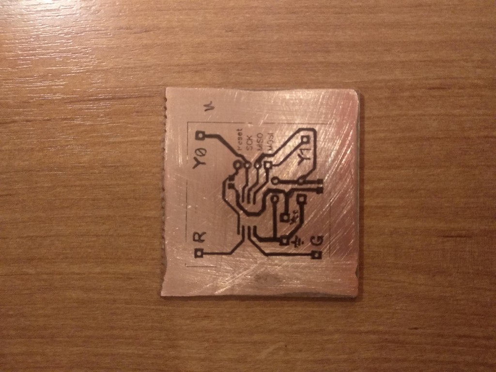
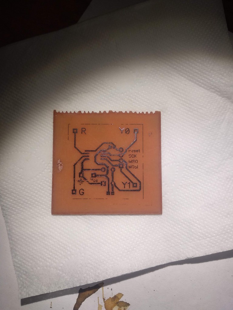
( ?) . — . , , , . , , .
DipTrace «» «PCB Layout», . , .
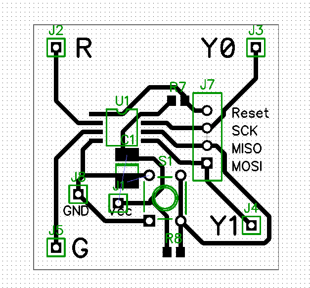
— .

, , .
( , 80- ).
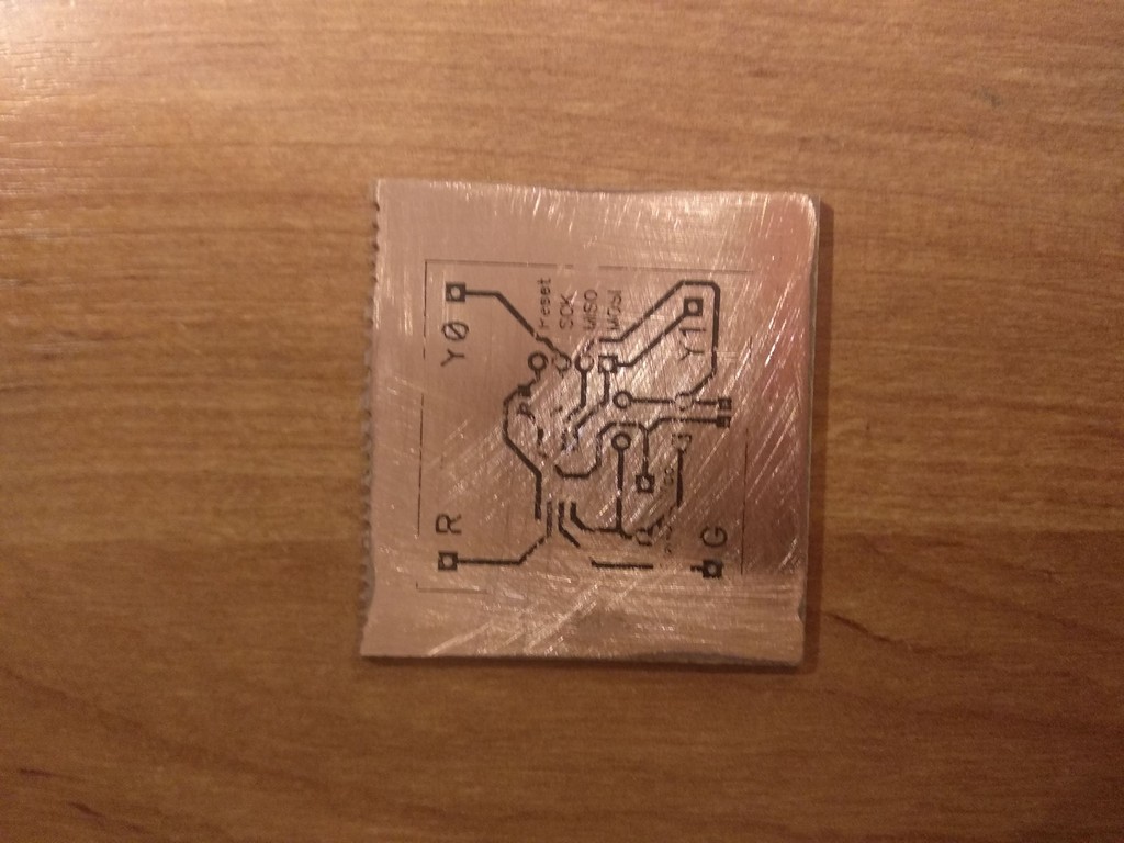
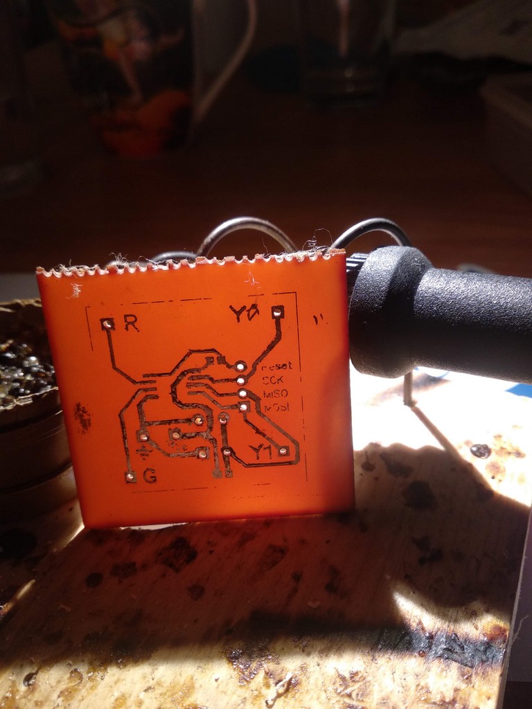
CD .
, , , .
— .
: , .
, , . — , .
Insides
— . - - "Craft&Clay" 50- 70. , .
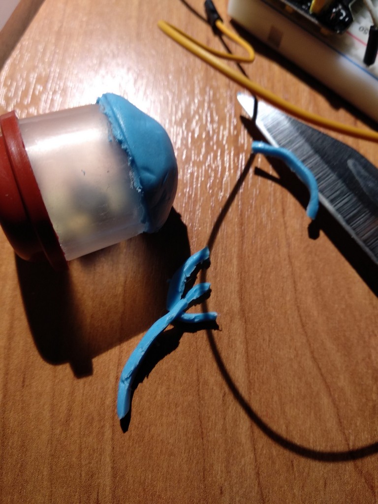
.
15 130 .
— .

— .
— .
.

4 , 2-3 ,
, .

. , , , " ".
, .
KSP. — 4 LED 5 .

, , DC-DC 0.9-5 , .
. , , .
, , , .
ISP 10- .
, , , - . , , " ". 1.5 , — . , .
| , | , %/ | , | |
|---|---|---|---|
| CR1212 | 18 | one | 0.250 |
| CR1620 | 68 | one | 0.950 |
| CR2032 | 210 | one | 3 |
| NiCD AAA | 350 | 20 | 98 |
| NiMH AAA | 900 | thirty | 375 |
| NiCd AA | 1000 | 20 | 270 |
| Alkaline AAA | 1250 | 2 | 35 |
| NiMH AA | 2400 | thirty | 1000 |
| Alkaline AA | 2890 | 2 | 80 |
| Li-Ion | 4400 | ten | 600 |
, . , , (2/100) 2890/(24 30) = 80 . , 2 , 32 ATtiny13.
: , GPIO, . — , ( 4 14 ""), , 40 .
, — . , . , : 5 DC-DC , , DC-DC 1.5 -> 5 . , - +-20%, .
, "" 4-5 (5 ) , , 25 (1.5 ),
.. 2890 116 , . ATtiny13 POWER DOWN . , — . 20-50 , , Hi-Z, 1 . , DC-DC .
2 5 . : .
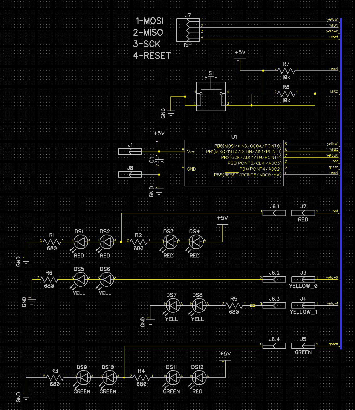
,
, :
- , — , R2, , . .
- . — 1/37 , .
- , , . POWER_DOWN 30 , , , .
- traffic_signals 8 4, . 4 pin — 1 DDR PORTB
- uint16_t signal_period flash_period — , , 1 .
- — ROM 2 , — - .
- /UART.
- main — — +50 ROM.
- 9,6 128 , .
But.
: " ", , 8 , , «» .
.
Github , MIT.
')
Source: https://habr.com/ru/post/443188/
All Articles