Pull YPbPr from Commodore 64
Commodore 64 - a computer with a huge library of programs, but with not very high quality video output. The microcircuit called VIC-II immediately generates S-Video, and the color signal is not quite standard, and the brightness signal is somewhat noisy. But, having removed the signals from the 22 outputs of this chip, it is possible with the help of the FPGA to find out what it is displaying at the moment, and to form exactly the same video signal, but YPbPr.
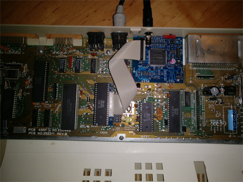
The author took as his basis his previous development - the A-Video board. It was inconvenient to install it in the C64 case, since it required the drilling of additional holes for the three “tulips”. The new board is designed for installation instead of a modulator. New holes are not required, in place of the antenna jack after reworking is a four-prong (TRRS) "jack".
')
The device consists of two parts:
- an adapter card that converts all 22 signals from 5-volt levels to a 3.3-volt
- FPGA boards connected to the adapter card with a loop and installed instead of the modulator; it also contains cascades for amplifying S-Video and composite signals, repeating similar modulator stages so that the corresponding video outputs continue to work.
The device is designed so that over time you can add support for all existing versions of C64: PAL and NTSC versions, short and long, with VIC-II power from only 5 V and from 5 and 12 V. The hardware is probably compatible with all variants are already done (a test with two boards — a long voltage supplying the chip with two voltages and a short supply voltage of the chip with one voltage) —but some varieties of the VIC-II chip (in particular, 6567R56A, found in early releases of the computer) are not yet supported by firmware. And these are already precisely supported and work:
- 6569R5 (PAL)
- 8565R2 (PAL)
- 8562R4 (NTSC)
The switch on the board can select the following output parameters:
- 240p / 288p, progressive scan 50/60 Hz
- 480p / 576p, progressive scan 50/60 Hz, double lines
- 480p / 576p, 50/60 Hz, imitation of strings as on a CRT
Purpose of the jacks starting from the contact of the plug opposite to the cord: Y, Pb, Pr, common. Therefore, any cable with a four-pin "jack" and three "tulips" is suitable, provided that the common wire corresponds to the contact "jack", which is closest to the cord.
The 240p / 288p mode is not supported by all TVs, but it is convenient to apply to external scalers. Both 480p / 576p modes work well on all TVs, as long as there is support for YPbPr.

Order rework:
- download all the necessary files (schemes, circuit boards drawings, firmware) from here , assemble boards, flash FPGA
- remove the VIC-II chip from the computer board, sometimes it requires moving a small amount of “crumbling” and installing the socket
- place the VIC-II chip in the adapter board, making sure that it is deployed in the same way
- install the adapter card with the chip in the computer board, if it is poorly kept in the socket, replace it with a better one
- check the board with the FPGA on weight, connecting it to the adapter card with a cable, then connecting one of the GND3, GND4, GND5 pads to the common wire of the computer, and the right pad of the RFCON2 kit - to the +5 V bus; in this form, the device can already output YPbPr -signals
- remove the modulator, clean all the holes in the board from the solder, where it was soldered
- in place of the modulator install two four-pin comb, but do not solder
- see which contact pads of the FPGA board to connect the comb: for computers with long boards, there is one set of sites on the FPGA board, for computers with short boards - another
- put the board with FPGA on the comb, align, then solder them from the side of the computer board
- put the board with FPGA vertically, solder the comb from its side
- if the VIC-II chip is powered by two voltages (its designation does not start from 8, but from 6), close the JPLUM1 jumper on the FPGA board
- if you, after checking on the weight, removed the train, return it back
It is possible to connect the FPGA board to the TV through the TRRS - three tulips adapter, through the same cord, or through the TRRS - TRRS cord, if the TV has such a YPbPr input with the same socle pin (see above).
Address to contact the developer: reinhard.grafl barks aon put at the end of the sentence at
Source: https://habr.com/ru/post/443182/
All Articles