Beautiful accurate watch from an old smartphone
The article will focus on how to convert an old unnecessary mobile phone into a great wall clock with large numbers, always accurate time and backup power.
I will talk about some clarified features of time synchronization in the Android OS, as well as about various electrical tricks in the smartphone's power system. I will describe an example of a circuit on simple analog components that provides automatic backup power. And of course it will be about the software part of the android - just like with the help of which you can make a beautiful watch for every taste from your smartphone.
( traditional disclaimer - any mentioned brands, trademarks, etc. are not advertising, I hope this is understandable. )
')
Second life to the old smartphone
I have long been lying around the old Philips Xenium W732. Fully working, with the whole screen. I decided to give it a second life - turn it into a wall clock. My old home clock, still Soviet, with flickering small numbers was very hard to see from a couple of meters away. In addition, they terribly lagged behind, they now and then had to be let down, and with any loss of electricity in the house they were completely reset and required a tedious procedure of poking buttons and setting the time again. I’ve been tired of all this for a long time, and I decided to make a good smart watch out of an old mobile phone, devoid of all these disadvantages.
What i needed
- Large, clear numbers of any desired color, font and brightness.
- Maximum accuracy and stability without any outside interference from me.
- Non-volatility, i.e. The clock must continue to operate during temporary power outages.
- Fully autonomous work, in the sense - without using any paid data networks, SIM cards, operators, etc.
- Maximum compliance with the “made, turned on and forgotten” principle. That is, the device should never require any maintenance, or even some kind of interactive.
We provide Android with accurate time.
The first thing was to get in the smartphone constantly accurate world time. The concept of “exact” for me quite fit into 1 ... 2 seconds of deviation from the world.
It is clear that the own system timer of the mobile phone will not give such stability of the course, it is not required of it. Therefore, guaranteed compliance with world time can only be obtained by regular external synchronization.
In the simplest case, in android, you can configure it using the "over the network" method. It does not even need a cellular network with the inevitable SIM cards and payment of tariffs. It is enough to distribute home Wi-Fi to your smartphone, and configure the router to synchronize the time from an Internet provider or ntp server.
However, there is a second synchronization method - using GPS satellites, which I personally think is better.
From the pros - you can synchronize anywhere in the world where the sky is visible. Absolute accuracy of time, since GPS itself is based on this. The absence of additional radio channels and radiation.
Among the disadvantages of GPS - the device must see at least a little open sky. In an arbitrary place in the depths of the room, nothing is likely to get caught, especially if the device has an old and insensitive chip. And since my watch was located exactly away from the window, I needed an external GPS antenna ...
The simplest external GPS antenna
On the Internet on this topic, everything was pretty tight. I immediately realized that I would not be able to make such an antenna myself - so far-over pretentious, bulky designs were offered everywhere with some complicated and intricate calculations. I tried to find a purchase - I didn’t like everything either. Some kind of all big, awkward, requiring external power, with a bunch of unnecessary functionality and while inadequately expensive.
The solution was found by chance - I somehow saw the description of the antenna type "half-wave dipole." In the simplest version, this is just a straight piece of wire with a length equal to half the wavelength of the desired signal. This “complexity” of the design suited me perfectly, so I just picked up the first coaxial with an arbitrary characteristic impedance and carefully soldered it to the smartphone on the corresponding contacts of the GPS patch antenna.
Contact photo GPS antenna on the W732 board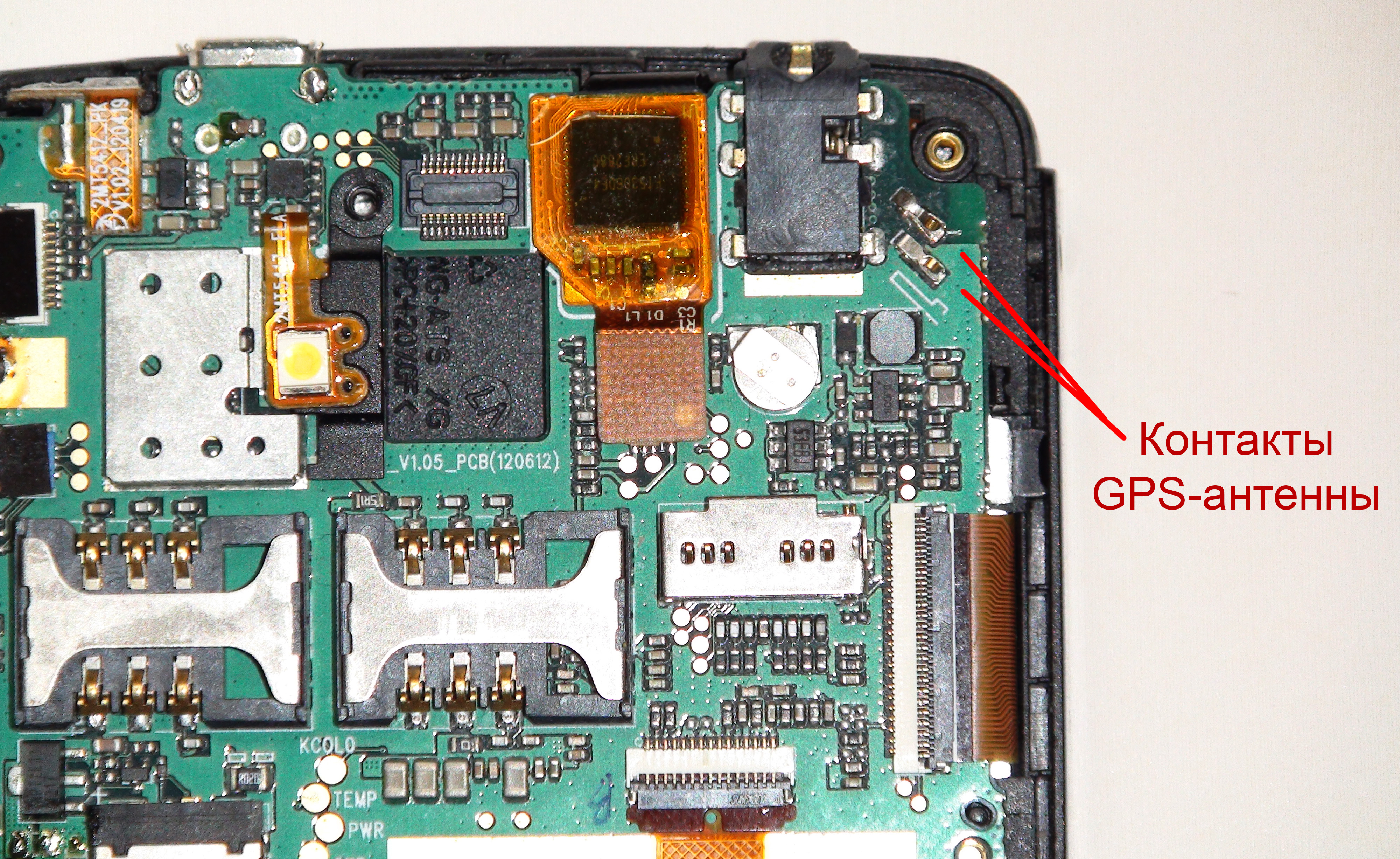
The braid and the central core of the coax are soldered to these contacts.
The braid and the central core of the coax are soldered to these contacts.
I simply removed the other end of the cable from the screen braid so that the central core with a length of 95mm remained - this is half the wavelength at the L1 frequency of the standard GPS signal (1575.42 MHz).
The simplest GPS antenna. Half wave dipole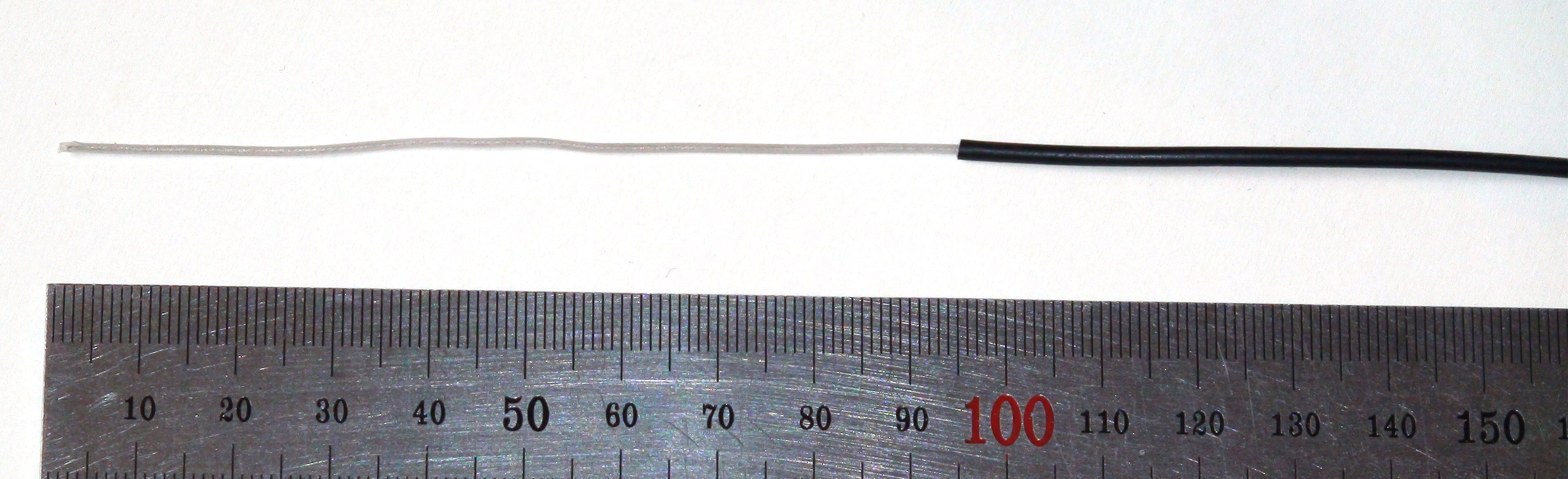
This antenna should be located as close as possible to the window.
I glued it to the glass with scotch tape.
This antenna should be located as close as possible to the window.
I glued it to the glass with scotch tape.
He took the phone away from the window, and the wire end, which was trimmed to 95mm, on the contrary, brought it to the window so that it could see the sky more.
And what - Phillips soon got his honest 5 ... 7 satellites and fixed! The antenna works!
And I was also worried about the alleged coordination of the wave impedances of the cable, antenna and receiver that I had been brainwashed on the Internet in antenna forums. Later I found out that such an impedance matching is necessary in order to simply obtain the maximum efficiency of the transmission line (no end reflections and excessive attenuation). And if the line is only 2 ... 3 meters, like mine, and the task is simply to deliver at least some part of the signal to the receiver, then this coordination can be avoided at all - everything will work with any coaxial.
Features of the GPS synchronization process
Having received a working GPS, of course, I immediately set the method of time synchronization “by GPS satellites” in the android settings and left the phone in this state for review. What was my surprise when a few hours later, time on the phone significantly "parted" with the control clock on the computer (where windows is synchronized via ntp). He began to find out the reason ... It turned out that the android, configured to synchronize time by GPS, actually performs this synchronization only once - at the moment of fixing the coordinates .
And then, even despite the fact that the smartphone continues to continuously track satellites, its system time is still determined only by the internal generator, that is, no synchronization is carried out at all! At least in my phillips on android 4.0.3 everything happens exactly this way.
For me it was an unpleasant surprise. I will not constantly manually pull the GPS to update the exact time ...
The solution was found software. I use the Locus software from Asamm software for navigation, in which you can configure not constant maintenance of GPS in the active state, but periodic one-time fixes of coordinates at specified intervals, that is, exactly what I needed. I set the interval to 15 minutes, and the problem disappeared safely - the time in the mobile phone from now on always clearly coincides with the world! For 15 minutes, the system timer of any normal smartphone does not accumulate a time error of more than 1 ... 2 seconds, which is fine with me. If you wish, you can fix in the hot at least every ten seconds.
Catering stationary smartphone
After the exact time was provided, it was the turn to make good nutrition for my watches.
As I already mentioned, I required that the clock not be turned off and not reset with short-term power outages in the house, which, although rarely, happen.
The first, the most clumsy solution here is to stupidly plug a smartphone into a socket and leave it that way. After all, at the same time, the problem with electricity interruptions is perfectly solved - the mobile phone will simply switch to a battery, which it will always be fully charged and ready for use. No sooner said than done. I plugged in ... A week passed, the second — I had already begun to rejoice ... And on the third, one fine day, there was a clap, and the battery happily flew out of the phone into the middle of the room, swollen with internal pressure to the state of a ball.
Regular Phillips Battery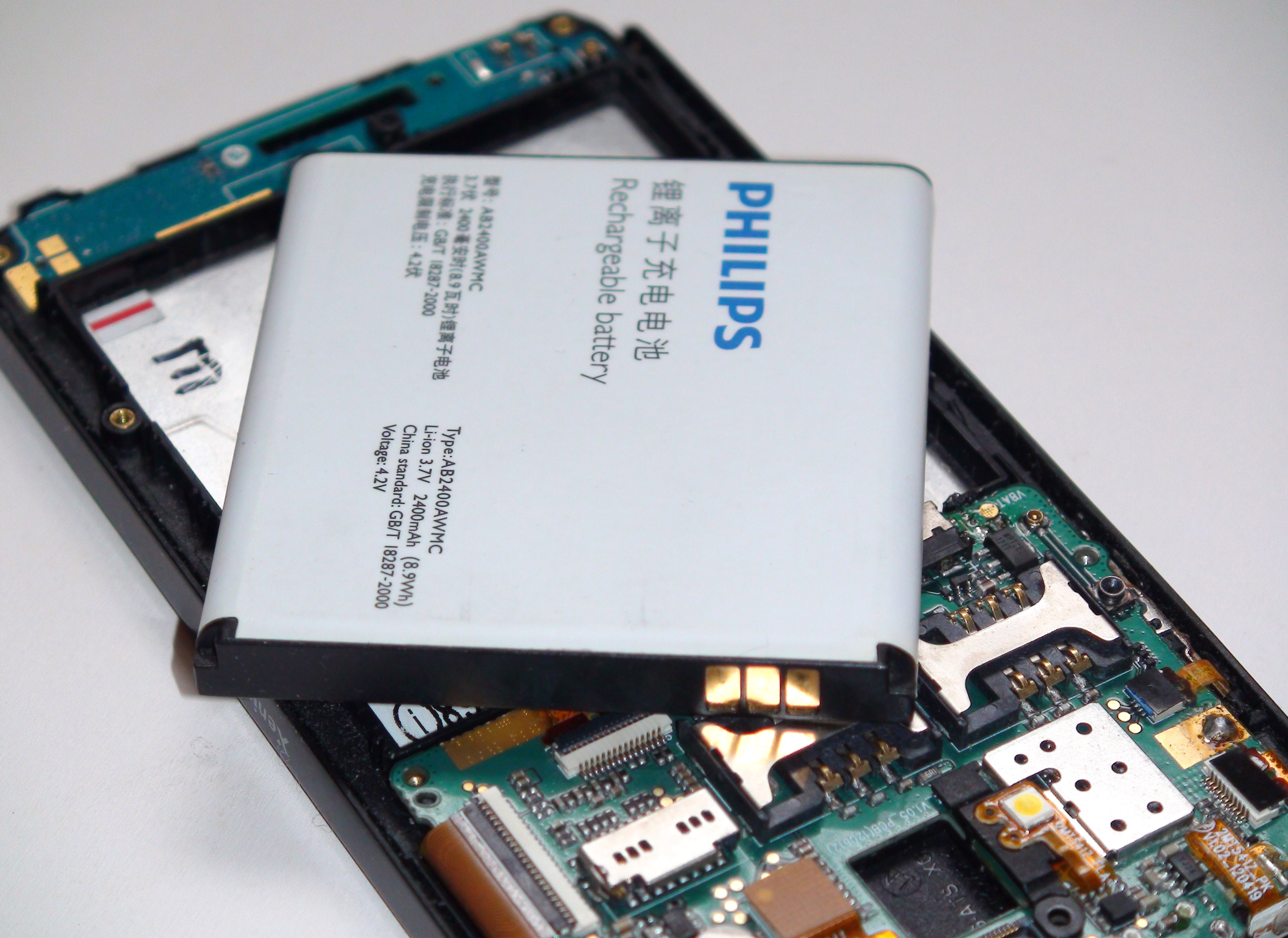
This is his normal condition. Flat and hard ...
This is his normal condition. Flat and hard ...
As you understand, I was still very lucky that the seams of the battery case weathered and did not open, otherwise I could not escape the lithium fire, smoke, stench and damaged linoleum.
There is only one conclusion - it’s just impossible to use your smartphone for months and years on a constant charge . Phone on such a scenario is not sharpened. Its main task is to correctly charge the battery to the maximum, not allowing the voltage and temperature to exceed. And then all the same discharge is assumed. If the device is never disconnected from the outlet, the controller usually begins to maintain a saw-tooth charge graph - first finishing up to 100%, then turning off the current and waiting for the discharge to be somewhere up to 90%. And re-charge again up to 100%. And this is a more or less caring approach. And many old phones can just stupidly always keep the maximum voltage on the battery.
It is known that the higher the voltage on a lithium-ion cell, the faster its aging and degradation. Some smartphones generally flood their batteries even above 4.2V to maximize battery life. And the result is the same - constantly being under maximum voltage, the battery degrades much faster. If it is also old, it is not far from the gradual development of microscopic internal closures, thermal acceleration and explosion, as it happened with me.
After the incident with an exploding battery, I wondered - how can I simultaneously have backup power and prevent the battery from being at full voltage all the time?
Went through many different scenarios, eventually settled on the following.
In normal mode, the phone will always be powered from the outlet, that is, 5V through the USB connector.
The backup battery is automatically and simultaneously charged to its normal maximum of 4.2V with the help of a simple additional circuit, after which it is completely disconnected from the charge . Then the battery is simply quietly discharged by self-discharge, not being connected anywhere. In this case, the circuit constantly monitors its voltage and re-turns on a one-time charge to 4.2 only when the cell voltage drops below a certain predetermined minimum (I accepted 3.6B). And so on, everything is on full automatic. The real time between these recharges is years, during which the battery self-discharges slowly, but nevertheless remains fully capable of supplying the load at any moment, even if not from its full capacity.
In cases of power failure from the outlet, the battery should be immediately automatically connected to the smartphone (as in bespereboynik), after which the system will continue to work from it autonomously until the mains supply is restored, or until the charge is completely exhausted (and turned off).
With this approach, the lithium cell is operated more sparingly than with constant maintenance of the maximum voltage on it. And certainly not explode!
The tricks of smartphone electrics
Now how to implement all this circuitry.
The point here is complicated by the fact that the smartphone was not so simple, everything is organized in the power supply system.
For example, without a battery, the phone will not turn on even if there is 5V via USB.
If you remove the battery while working from USB, everything goes out immediately. Although the power at the same time clearly comes only from the USB-connector!
Even at first there was a problem with the third contact of the battery. I did not want to be tied to a standard Filipovsky battery and decided to find out - what will happen if you leave the terminal of the third contact not connected at all? It turned out that the smartphone will not turn on at the same time ... I even began to fear that some average digital bus, such as i2c, goes through the middle contact, which transmits not only different technical telemetry to the phone, but also all sorts of factory-friend-style codes. This would mean that I was forever tied to my native Philips battery, because I definitely didn’t intend to bargain with some kind of cheating digital interfaces (I remember I had a similar surprise when working with camcorder batteries from a world famous and respected Japanese company).
I looked at the oscilloscope what is happening on the third contact. On my happiness at the Philips W732, everything turned out to be very simple! There, the usual constant voltage from the internal battery temperature sensor is displayed. The input of the third contact in the smartphone is high-impedance.
I assembled a simple trimmer divider, and, applying different voltages to the middle contact, removed several points of dependence of the battery temperature displayed by the android on the voltage at the third contact.
Graph of the displayed temperature of the battery from the voltage of the 3rd contact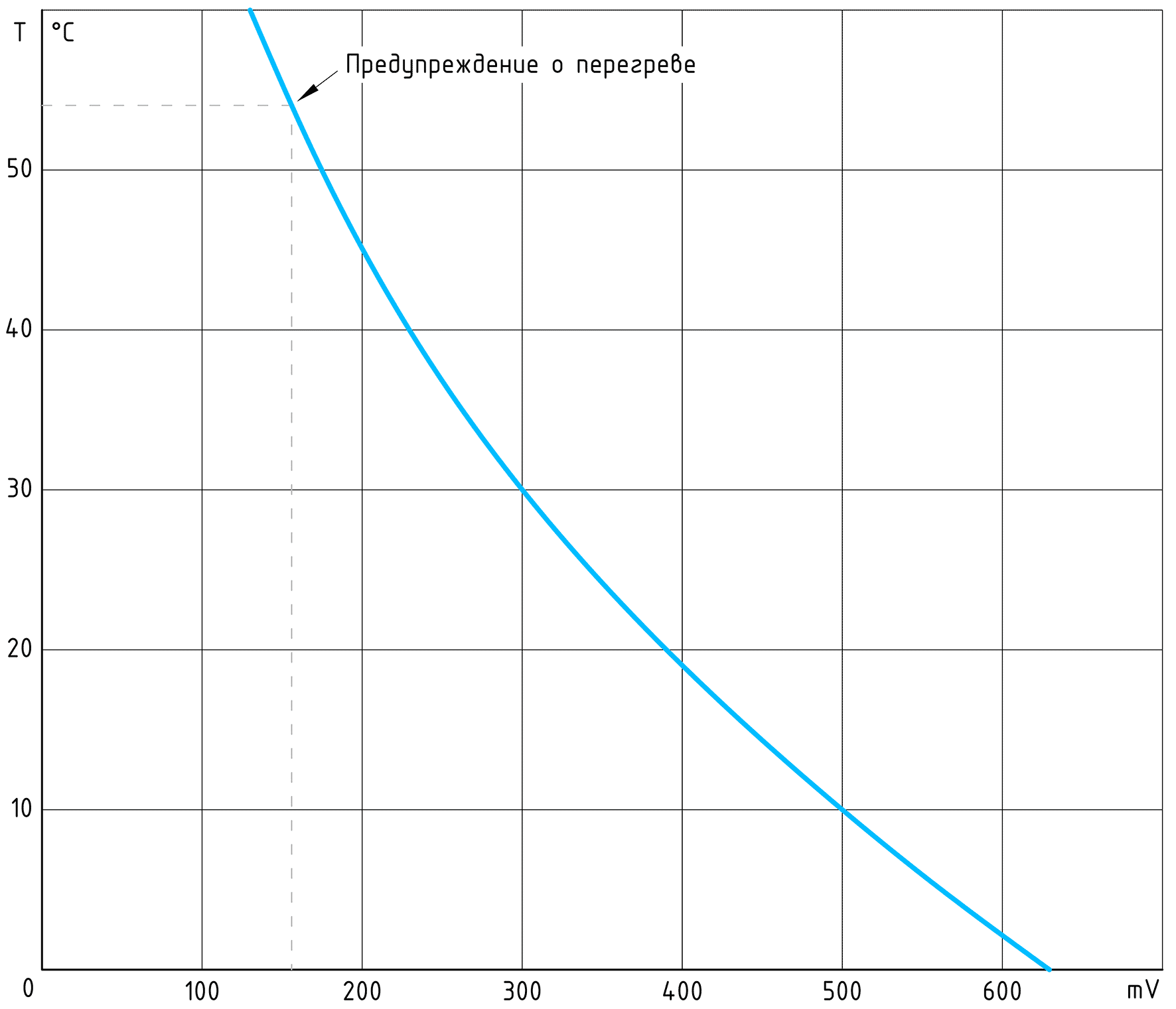
It turned out that if the third is less than 153mV, full-screen warnings of battery overheating will start and the phone will turn off after a few seconds. When the voltage is above 630mV, the android begins to assume that its battery has frozen to minus temperature, but will continue to work (and even silently!). Then I did not need to experiment anymore - I just realized that it was elementary to fool the third contact here - just submit there any potential between 155 and 600 mV.
As a result, I have formed 2 criteria, without which the smartphone does not work at all:
1. Mandatory voltage on the positive terminal of the battery (despite the fact that the system is powered by a USB connector)
And it should not be some kind of fake snatch of potential, just so that the phone thinks that a battery is inserted into it. It requires a full-fledged low-impedance voltage source with a current of at least the operating current of the smartphone.
2. The presence of a constant voltage on the third contact of the battery pack in the range of 155 ... 600 mV. There is already quite a simple high-void potential-blende.
By the way, I still don’t understand why the android has such a high shutdown threshold (3.4V), while a standard lithium cell can easily be safely discharged to 3 or even 2.8V! The only thing that comes to mind is the presence of 3.3V internal consumers in smartphones, which need a supply of power for their buck-converters. But SEPIC can be supplied and used more fully! Or in the modern age nobody thinks about this?
Then I had to come up with a simple auxiliary scheme that would follow all this and automatically control it. I immediately decided that I would not use any microcontrollers, although I could work with them. In this case, you just had to think a little, optimize everything thoroughly, and all functions were implemented on simple analog components. Everything works and never freezes.
The backup clock battery is required periodically from something to charge. At first, I decided to do it right from the battery plus of the smartphone, because I naively believed that he had honest and unchanging 4.2V there. With the help of an oscilloscope, I looked at what was going on in reality. It turned out that no constant levels there and does not smell! ..
Firstly, if nothing is connected to the battery positive output, the charge controller still does not sleep and periodically “pinches” it with its checks.
Oscillogram of voltage on the battery positive terminal
( reconstruction of a real waveform )
( reconstruction of a real waveform )
You see - about every 45 milliseconds, the phone gives out a ladder from successive “probing” - did the external voltage appear on the battery contact? And between these checks keeps a certain level of 4.05V.
If you connect a battery, the system recognizes it and regularly starts to pour current there. But, again, not all the time, but in periods of 10 seconds. Every every 10 seconds of charge, the smartphone turns on a full reverse current for 2 seconds, i.e. selects the current from the battery, and with a decent power (I did not measure the exact numerical values of all these parameters, I was interested in the principle). During this brief current take-off, the smartphone measures the battery charge under load, thus obtaining honest numbers of percentages and voltages. It was clearly visible how exactly after this reverse the values of all battery parameters are updated in the android.
This whole tricky mechanism of charge did not suit me at all, and even interfered, because I assumed to build the logic of charging circuits based on continuous analog voltage monitoring on the measuring shunt. And automatically turn off the charge when the drop on the shunt would drop to the specified minimum, indicating that the charging current has reached the final charge stage. And then this reverse completely spoiled everything ... I first tried to somehow get around or deceive it, but as a result I realized that it was easier to use an external source of reference charging voltage. It will be more reliable and transparent for further understanding.
I put an external integral stabilizer (normal, linear), with which I received from a poorly stabilized 5 ... 6V USB charger accurate and temperature-stable 4.2V. With them, I, first of all, energized the smartphone's positive battery terminal so that it always thought that it had a 100% charged battery and never broadcast anything about it on the whole screen. And secondly, the backup battery charge system works from this bus.
Along the way, I came across a curious observation. It turns out that if you turn off the power via USB and apply a constant voltage from a stabilized source to the battery terminal of the smartphone, which will never change, the android will still persistently draw a sloping, falling percentage charge graph! Apparently some kind of equation for calculating these percentages is entered into the program for monitoring the android battery, which takes into account not only the actual cell voltage, but also the current consumption of the device. I specifically conducted experiments, turning the screen backlight on and off, as one of the most voracious current consumers. Here are some statistics scored per day:
So android drew a graph of "battery discharge"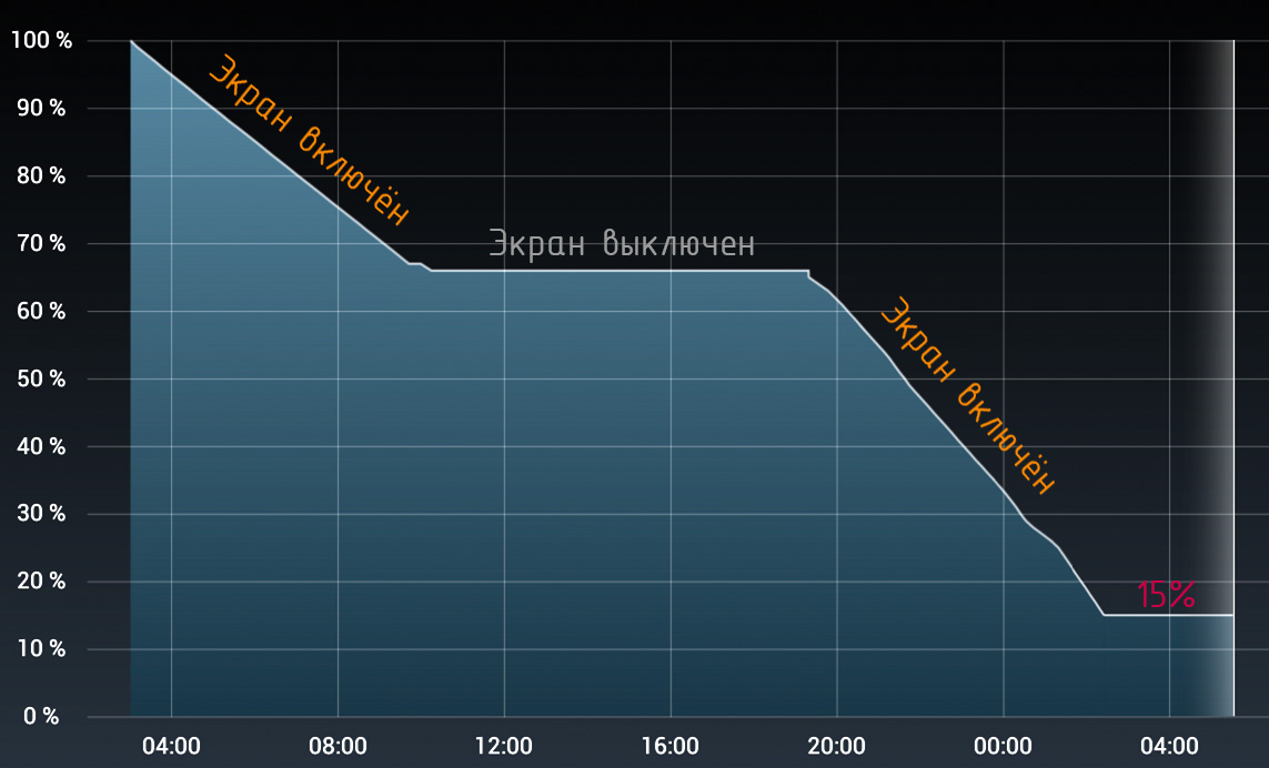
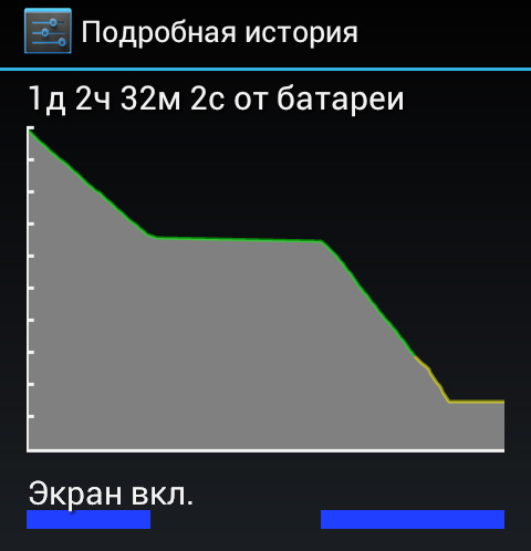
You see, when the screen worked and the current from the battery terminal was perceptible, the android drew a good slope, about 5% drop in an hour. Then I turned off the backlight and the smartphone fell asleep, the current dropped to some small duty values, and the graph went virtually horizontally. I turned on the screen again - and again the ramp. Note that the voltage on the positive terminal of the battery has always been strictly constant . So the android calculated its percentage of charge only on the basis of the measured current.
However, as soon as the charge reaches 15% (here the phone gives a warning about a discharged battery), the schedule stops falling and continues to horizontally 15% further ... This is such a trick (or glitch).
There was another feature. It turned out that if you simultaneously power on the USB connector and stabilized external power to the battery terminal, but less than 4.2V , the smartphone will firstly show an incomplete percentage of charge for a long time and honestly, and then suddenly begin to scold, in the style of with a battery! The charge goes on too long! ". And of course, all this is again in full screen and on top of my watch!
Well, if you submit more than 4.2V, then already somewhere from 4.3V it will start swearing about the dangerous excess of battery voltage, this is understandable. Therefore, the "range of peace" here is quite narrow - only 0.1V.
And only if he is provided with 5V power supply via USB, and full emulation of accurate 4.2V across the battery terminal - only then the android happily pauses, believing that he honestly charged his battery to the maximum. And the more he already, thank God, never complains of anything!
Immediately calm those who may have thought that I did very badly by loading the two mismatched low-impedance voltage sources at each other (i.e., an external 4.2 V stabilizer and a positive battery terminal, which itself also “feeds”) . The fact is that my external stabilizer is an ordinary linear LDO and is not able to divert current in its circuitry. Only let down. Therefore, no electrical conflicts arise here, as it can happen, for example, when several different batteries are connected in parallel.
Scheme
When the TOR was finally fully defined, it was possible to start developing a specific scheme. Despite the seeming simplicity of the task, I fussed with her notably! I had to think and then reject more than a dozen different options, from obscenely simple to cumbersome. Here's what happened in the end:
Power plan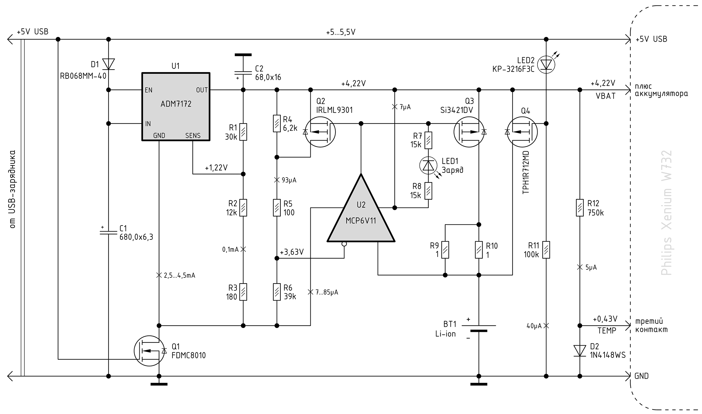
Despite the apparent redundancy, the scheme is simple. Thanks to SMD, a shawl with a size of 35x22 mm easily fits inside the compartment of the removed standard battery. As a backup battery, I used a conventional lithium-ion 18650, mounted on a watch stand.
The circuit provides the following functions:
- The main constant power supply 5V from the outlet through the USB connector.
- Automatic transfer of the smartphone to the backup battery when the power is lost from USB.
- The supply of a stable 4.2V to the battery terminal of the smartphone (so that the android is always calm).
- Voltage emulation for the third battery contact (in any power mode).
- Automatic start of the backup battery charge when its voltage drops below a predetermined level.
- Charge backup battery for a simplified but safe law.
- Automatic cessation of charge to achieve a given amount of charging current.
- Backup battery does not always hold at maximum voltage.
Now briefly how the circuit works.
To get a stable and temperature-independent 4.2V, I applied the wonderful integral LDO ADM7172 from Analog Devices. It gives me the necessary and perfectly even voltage of 4.22V up to 2A load. I let him into the smartphone on the plus battery connector (VBAT), and also use to charge the backup battery of the system.
The voltage emulation circuit for the third battery terminal (TEMP) is made on a simple D2 diode, powered by a meager background current.
P-channel mosfet Q4 connects to the smartphone backup battery as soon as the main power supply bus + 5V USB voltage disappears. LED2 LED is here only for the purpose of level shifting to slightly accelerate the opening of the Q4 in the process of tire collapse. It is infrared and does not shine anywhere.
The rest of the details made charge scheme. The backup battery BT1 is charged through the mosquet Q3 and the control limiting resistor R9R10.
The work of Yow U2 is interesting here. It is here turned on so that it provides control at the same time as the degree of discharge and the degree of charge. The OS operates here in the comparator mode, and the positive OS for it is obtained by itself due to the processes in the circuits it controls.
Here's how it happens: when everything is fine - there is a power supply of + 5V USB and the backup battery is charged up to a voltage, higher than set by the divider point R4R5R6 - then the op-amp gives the output a 4.2-volt bus (from which it is powered) and the charging mosfets Q3 closed. When the battery for some reason or other is discharged below this point (+ 3.63V in the diagram), the output of the op-amp will gradually “come off” from the plus and thereby open the charging mosfet Q3. A current will flow into the battery, the voltage on the cell will immediately grow by at least a few millivolts (due to non-zero internal resistance) and this will serve as a reliable PIC for the OS. Here you can apply a real comparator with its own hysteresis, but in reality, the amplifier is switched reliably and quickly, there are no rattling drifts.
The battery charge goes through a resistor R9R10 (it is composite in order to increase the power dissipation). Firstly, it limits the charging current, which is absolutely necessary here, otherwise even the 2-amp charger simply won't cope and will squeeze. Secondly, by the voltage drop across this resistor, the circuit determines when it is necessary to turn off the charge.
It happens this way: as soon as the charge is turned on, the auxiliary mosfet Q2 opens at the same time, which rebuilds the control divider R4R5R6 for the inverting input of the op-amp, and thus the op-amp starts tracking the voltage that is released on the charging resistor. At the very beginning of the charge, when the battery is completely discharged, the R9R10 drops to about 0.5V, which is why the op amp is reliably unbalanced in the state of charge mode. And only when the battery gradually fully charges, the current through the control resistor weakens to a certain value (approximately 20 mA), then the potentials of the OU inputs are equalized, after which it is transferred to the opposite state (plus output) by turning off the Q2 and Q3 and stopping the charge.
As for the resulting such a schemeThe charge profile of the lithium-ion battery, the resistor R9R10 here automatically implements a simple charging function with a maximum initial current, its automatic gradual decrease and approaching zero.
Charge function graph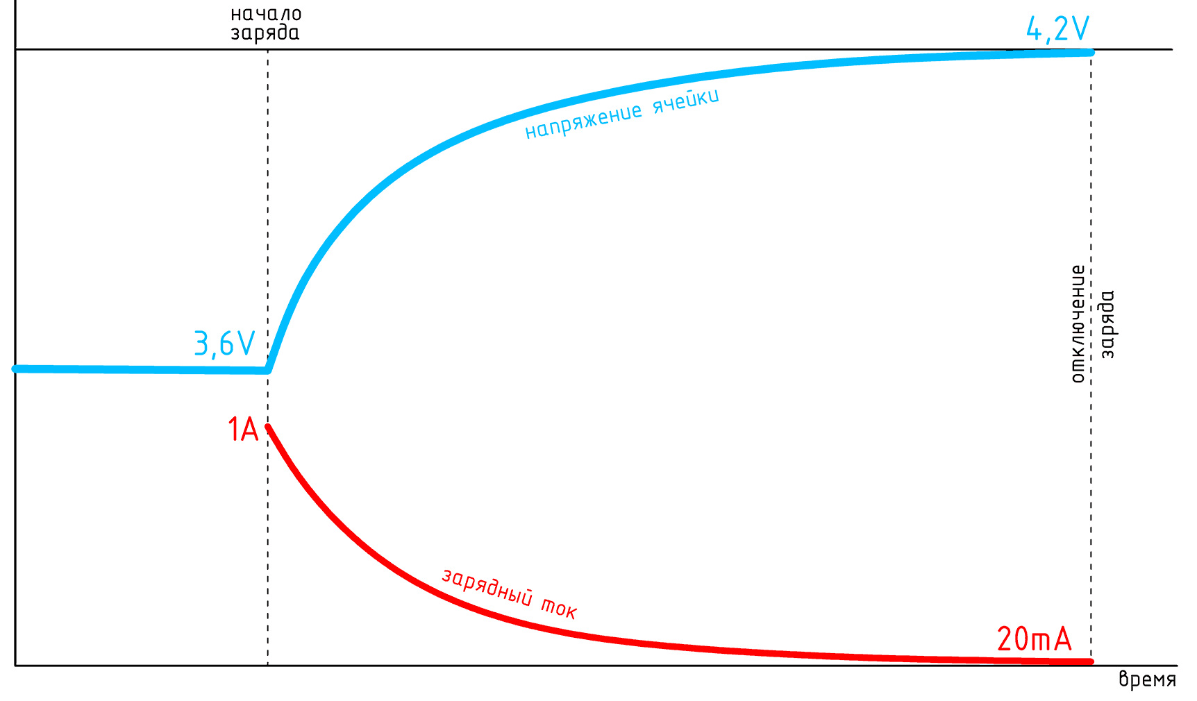
Battery manufacturers, in turn, recommend the following well-known charge profile with areas of current or voltage stabilization:
Typical recommended charge profile for Li-ion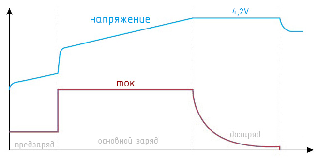
In my case, neither the voltage nor the current on the cell will ever specifically stabilize, but the voltage on it is guaranteed never to exceed safe limits. Therefore, I consider such a simplified method of charge to be quite efficient and effective. In practice, it works perfectly, and at the same time requires only one resistor.
Mosfet Q1 is used to ensure that when operating only from a backup battery, it does not waste its current to power the rest of the circuit. When the power supply is lost from the outlet, Q1 closes and cuts off all the unused part of the circuit from the common wire. Due to this, the own consumption of the entire structure drops to an insignificant 3 ... 5 microamps, and this automatically prevents a deep discharge of the battery if you forget about the de-energized system for a long time.
The Schottky diode D1 at the input to the stabilizer U1 performs a double function - blocking the reverse current through U1 (inside the ADM7172 there is no such blocking) and unloading the stabilizer microcircuit from excessive power dissipation. At the very beginning of the battery charge, the charging current reaches 1A, and if the entire 1 volt voltage drop from the + 5V USB bus is put on a tiny ADM7172 3x3 mm in size, it will be very hot, even despite the thermal pad soldered to the board. Therefore, part of the input voltage is successfully extinguished on the blocking diode D1, and as a result both of these parts are heated more evenly and not so much.
About used components
As an input stabilizer, I used a great LDO with a really low minimum drop throughput, although in this place the voltage on it never drops less than 0.4V. Just ADM7172 I really like it in many of its characteristics. And so here you can put almost any microcircuit of the linear stabilizer, the main thing is that it gives reliable volts, not floating on temperature, and at least 1.5A of current.
From the Mosphets, I needed here the minimal resistance of the channel in the open state (RdsON). This is especially true of the Q4 bit P-channel key. There I put a magnificent Toshibov model TPH1R712MD - the best that was found on the resistance of the channel in a small flat case. In its open state, it has a real 1.3 mΩ, which, with a smartphone operating current of 200 ... 300 mA, gives transit losses of valuable battery voltage at the level of insignificant 0.4 mV!
It is also desirable to have low RdsON for Q1 in order to more precisely link to the potential of the common wire. Fairchild MOSFETs FDMC8010 are doing fine with this too. There are lower impedance specimens, but in this design I was also important for the small dimensions of the parts.
The rest of the mosfets can be any, it is desirable only that they have less opening threshold voltage.
As a comparator for U2, I used Microchip's micropower MK6V11 iow, which I liked with its excellent economy - only 7 microamps in the background. True, compared to conventional Iow, it is certainly slow as a turtle (GBW 80kHz and a slew rate of only 0.03V / µs). But it still works great here. By the way, I tried to put here a real comparator with built-in hysteresis. I found an excellent sample of the MCP6541, which consumes only 600 nanoamperes (!) In the background, and when triggered it can pull the output with a force of up to 30mA ... But, having put it directly instead of MCP6V11 (their pinout is the same), I suddenly got a circuit failure. It turned out that the MCP6541 switches so fastthat the high-speed front of its pulse easily penetrates through the interelectrode capacitance of the gate Q2 into the control divider circuit R4R5R6 and falls on its own inverting input. Such dynamic feedback is obtained, and the comparator does not switch, but begins to generate.
The problem will be fixed by simply adding a high-resistance resistor between the comparator output and the Q2 gate, but I already had a ready board on which even for one additional small SMD resistor there was absolutely no room, so I just left MCP6V11 here.
LED1 LED is only needed to indicate when a battery is charging. In an amicable way, this should occur every few years ... You can use absolutely any, any color, but you can not put it at all.
Resistors and capacitors are the most common SMD, no requirements for them, except for small size. I used tantalum capacitors, lowESR, in 7343H housings, but any will fit, if only they would fit into the battery compartment along with the board (in the W732 it has a size of 55x60x8 mm).
In the process of charging the battery, the entire board heats up decently for the first couple of hours, up to 60 degrees. Since there was still enough space in the compartment, I deliberately increased the board area and spread the heated parts on it wider so that they would not overheat each other and the rest of their neighbors.
Power management board in the battery compartment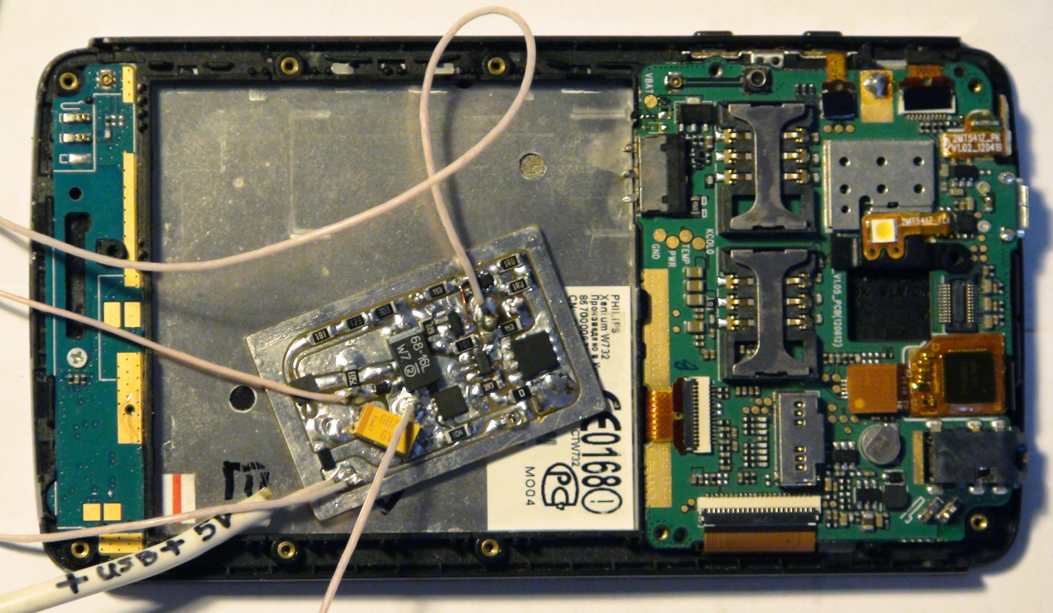
Made by hand, photoresist. The FR method makes it easy to get a “technical process” of 0.15mm, but for some reason I have all the textolite of such bad quality that thin roads strive to fall off when tinned ... If anyone knows where you can buy a good quality textolite with a guarantee - write in the comments !
So, the smartphone is finally properly powered, and works "like a clock" in every sense! Stable on as with power from the outlet, and from the battery, it works silently. When the charger is connected, it always shows 100% charge. If you unplug it, it continues to work quietly from the backup battery, and soon begins to display the actual voltage on it. When the mains supply is restored, again silently and calmly it shows 100% charge. All right!
In principle, through a similar scheme, you can power up any mobile phone, in which a simple constant voltage is transmitted to the third battery contact.
Digital Watch for Android
On this with the iron case was completed. It is time for software stuffing. Namely - it was necessary to get a large digital clock on the smartphone screen.
Here is what I needed:
- The largest numbers! I don't like to squint and gaze at small fry from afar.
- Ability to put any font of any color. On this, too, the readability depends.
- The exclusivity of the display of hours on the screen - nothing but the digits of time should not be there. No weather forecasts, warnings, messages, status lines and other nonsense should never appear.
- It's clear that the screen of the smartphone should never have gone off by itself.
- Competently working function auto screen brightness.
- Maximum reliability of work (I still live on this watch). Hangs, friezes - all this is excluded.
I started by charging the phone and mercilessly uprooting from there all the rubbish I managed to reach. All sorts of gapps, blots and everything that is not required for normal loading, flew into the basket. Including a bunch of system applications, various utilities for working with SIM cards, dialers, SMS, browsers, calendars, wallpapers, and other nonsense. A couple of times I even went too far - the phone was looping with errors. But I restored everything and cleaned it out again.
Then I searched for a long time on the Internet a normal program of full-screen digital watches for android. Despite the whole mountain of similar programs, practically none of them suited me! All developers polls are trying to cram a bunch of unnecessary things into their products - from some jolly background (non-switchable) to weather forecasts, news, calendars and other similar garbage. I keep quiet about the pop-up advertising that has already got everyone ... I only needed time from the clock!
And also the universal feature of watch programs and widgets is completely uneconomical use of screen area. Tsiferki everywhere small, and indents from the edges of the screen are huge. My Phillips has a not so big screen - only 4.3 ".
In short, I found almost the only suitable program - Big Digital Clock 1.1.1.
Screenshot Big Digital Clock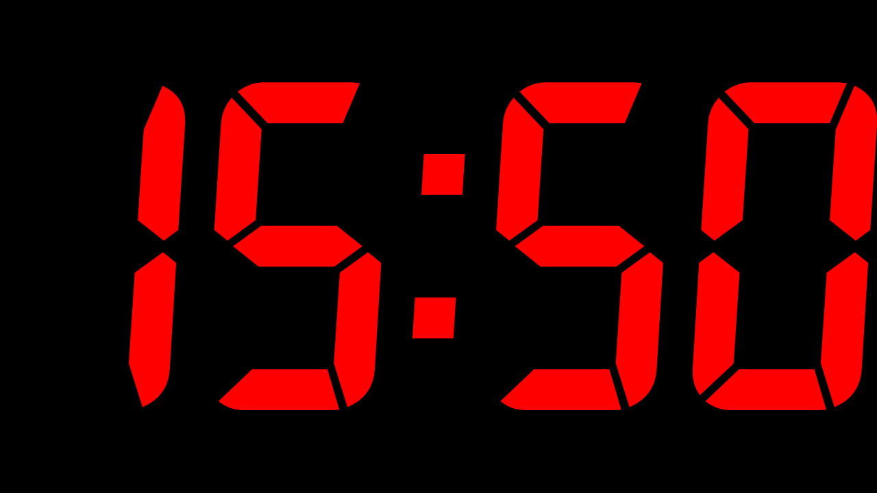
She has the biggest numbers. Still, they are still far from the full use of the area of the matrix. From the advantages of the program - the ability to remove from the screen everything except time, the ability to choose any color, 24-hour format, non-flashing separating colon, any orientation of the screen and automatic maintenance of a non-dimming backlight. Among the shortcomings is a tightly wired font imitating a typical seven-segment segment.
Put it and started everyday use. At first everything was fine - the figures seemed to be large, they were visible normally, and after my old clock - heaven and earth in general! But then, after about a month of continuous work, I suddenly noticed that the time was frozen and did not change! What kind of nonsense !? I decided to check - this is a one-time glitch or "feature" of the program.
I restarted the clock, and after a couple of weeks, the frieze repeated. The time just stops updating. Instead, the program randomly hangs down every 7 ... 10 minutes, updates the clock and again falls into a stupor. It is clear that this "reliability" did not suit me.
Android automators and their "chips"
Since this was practically the only suitable program, I had to start inventing crutches for it. I decided that I need to install some android automator so that it periodically restarts the buggy clock program before it even has time to hang. Put a tasker. I messed around, understood - but he didn’t like something for me ... I changed it to Automagic. Who does not know - this automator uses the construction of scenarios based on visual flowcharts. And this feature of it I really liked!
Representing automation scripts as Automagic flowcharts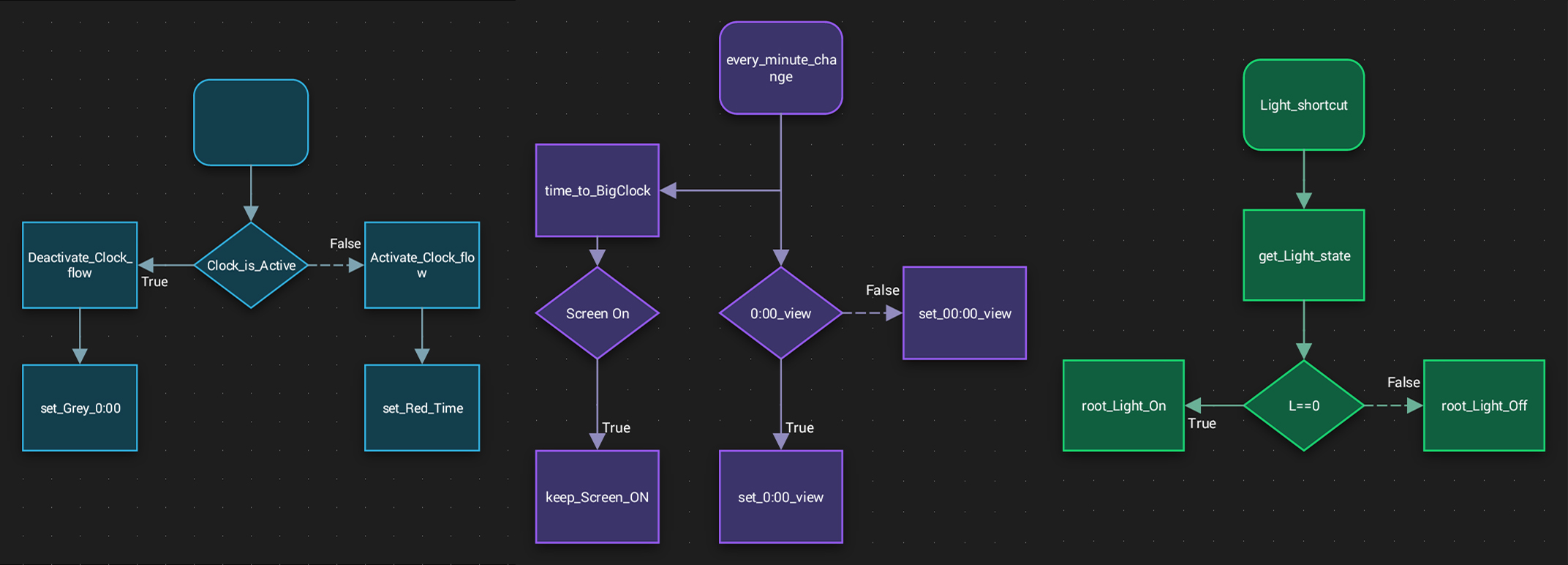
I implemented the function of periodically restarting my buggy clock program almost immediately. And then I put Automagic on my main working smartphone and hung up for a week in the most interesting experiments with it. As a result, I made a lot of utilities for everyday life in my phone.
But the main thing was not the case. I found in the properties of Automagic on such a chip as Custom Widgets. And it turned out that with its help you can draw and “animate” almost any homemade widget , which only has enough imagination and functionality of the program! Then I realized that I could draw myself such a watch, which only my heart desires! Yes, even in the program help, an example of creating a clock widget was described.
After a couple of days everything was ready at its best! Thanks to the Nova Lancher, I have the opportunity to stretch widgets even to the very borders of the matrix. I also hid the dock bar and status bar, freeing the screen from all interface elements. And that's what the result - really huge numbers relating to the very borders of the display ... Finally satisfied !!!
Finally, the numbers occupy ALL screen width!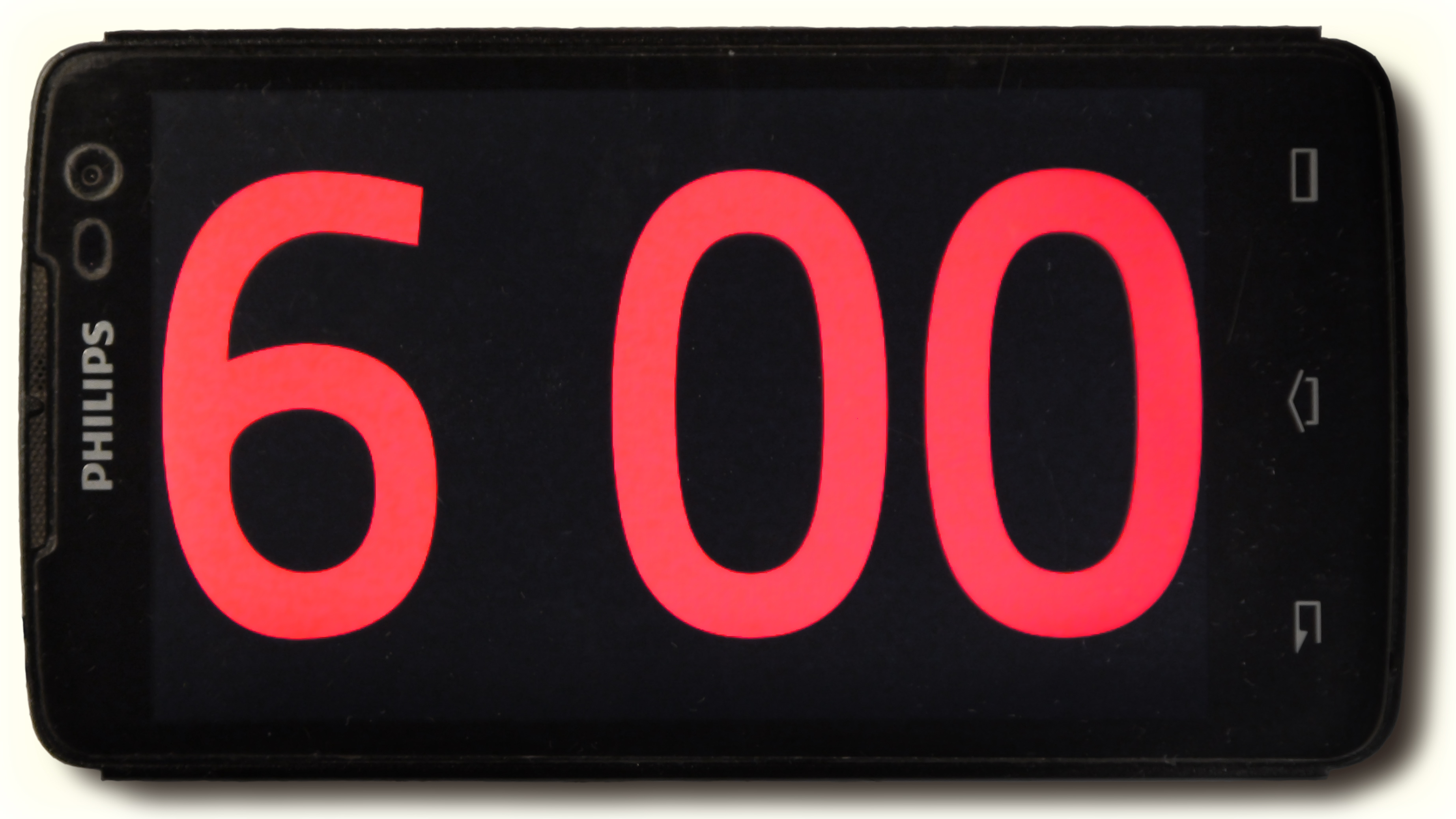
The use of Automagic allowed to satisfy all my requirements. You can put any .ttf or .otf-font. You can tighten and stretch the characters in any proportion to fit them perfectly into the screen. Finally, you can only have what you need! I didn’t even draw the separating colon in the clock - everything is perfectly readable with a simple space. The use of any external programs and crutches immediately eliminated all need.
Moreover, now I didn’t even need Locus to periodically fix GPS coordinates for time synchronization. All this is perfectly able to any automator. In the control script, you can implement almost everything you need. For example, keeping the screen in a state of inescapability.
Then all went zamorochki with different polishes appearance. And why not, if all this can be easily implemented?
For example, when choosing a font size and width factor, you need to start from a 4-character time format (XX: XX). But in the period from 0:00 to 9:59 the figures on the screen are only three, they occupy a smaller width than four, and thus use the matrix not completely. Trifle, but ugly. With the help of Automagic, a case is easily solved with a couple of additional commands. It has a function that allows you to change almost any parameter of a custom widget on the fly . In this case, it is a factor of width (flattening) of the characters of the font, which I asked to change by triggering the above time intervals. Works!
Three and four characters fit in the same screen size.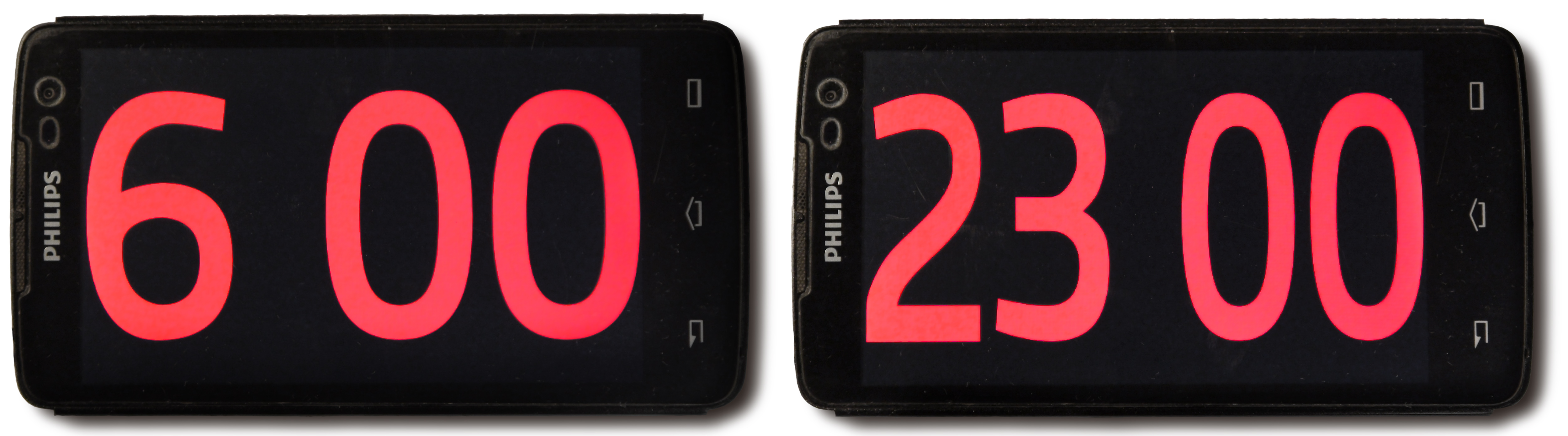
The font width factor changes “on the fly” when going from 9:59 to 10:00
and back from 23:59 to 0:00
The font width factor changes “on the fly” when going from 9:59 to 10:00
and back from 23:59 to 0:00
I also first had doubts about the moment of updating the readings of the watches that occur every minute. I was afraid that Automagic would update the widget not synchronously with the minute change of the smartphone's system hours, but arbitrarily, thus introducing random error within a minute. Began to check ...
In Automagic, there are two different ways to implement time in a custom widget. You can send numeric values to an external action event in a regular widget text field. For each such event, there is just a special option “At fixed time”, which means that it is necessary to send it synchronously with the moment of the system time change.
And the second way is simpler - it does not use external scripts and consists in writing the type system call function directly into the desired text field of the widget.
{getDate(),dateFormat,HH:mm} But there is no such option “At fixed time”. The widget is simply ticked “Automatically refresh” and set to “Refresh interval” in exactly one minute. And here my fears were precisely the fact that this one-minute widget self-renewal interval can be arbitrarily measured relative to the time grid of the minute change of the system time. I spent a couple of experiments, but it turned out to me that everything was fine. The widget self-updates clearly as soon as the system clock minutes changes!
Regardless of at what point in time the widget started working.
Auto screen brightness
The next thing I wanted to do was a good clear screen auto brightness. The built-in auto brightness on my old Philips worked terribly. Jerky, inadequate and with a very narrow range. Here I did not bother and put one of the many auto brightness programs. At first I tried Lux, but I didn’t like some non-intuitive tinctures and tangled profiles. Changed on Velis, and it turned out that it is necessary. What I particularly liked - Velis gives you the opportunity to draw a real curve of brightness versus lux meter readings and in real-time shows on this graph how the smartphone adjusts its brightness. You can adjust any o-very smooth law of brightness variation and of course any of its value, up to 1%, when the screen is almost not visible. Very handy at night when the numbers should barely glow.
While I was testing the new watch, I noticed that the matrix of the smartphone, even with an absolutely black background of the screen, still shines decently through the backlight penetrating through it. This is especially noticeable in complete darkness - the screen rectangle can be clearly seen as a gray background, something like a glow effect. I decided to fix this with an external light filter. The color of the numbers of hours I chose red, because red color I see most clearly from afar.
I made the first light filter manually — printed a solid red fill on an inkjet printer on a transparent film and folded two more raw prints in ink to each other. Films reliably stuck and it turned out a good transparent “glass” of thick red color. By the way, now such a life hack is no longer a ride, trite because at my place absolutely all inkjet printers were replaced with fashionable laser MFPs. On paper, they print beautifully, but using them to get a transparent color fill on the film is impossible - there will be a noisy matte layer through which nothing can be seen.
But here I somehow went to Comus for pencils, and accidentally saw just such a thing:
A photo
This is the usual office paper tray, but look what it is made of. Either plexiglass, or transparent plastic, but just the color and light transmission that I need for the filter. I bought it, carefully cut a plate out of it to fit the screen and adapted it. Beauty!
With red light filter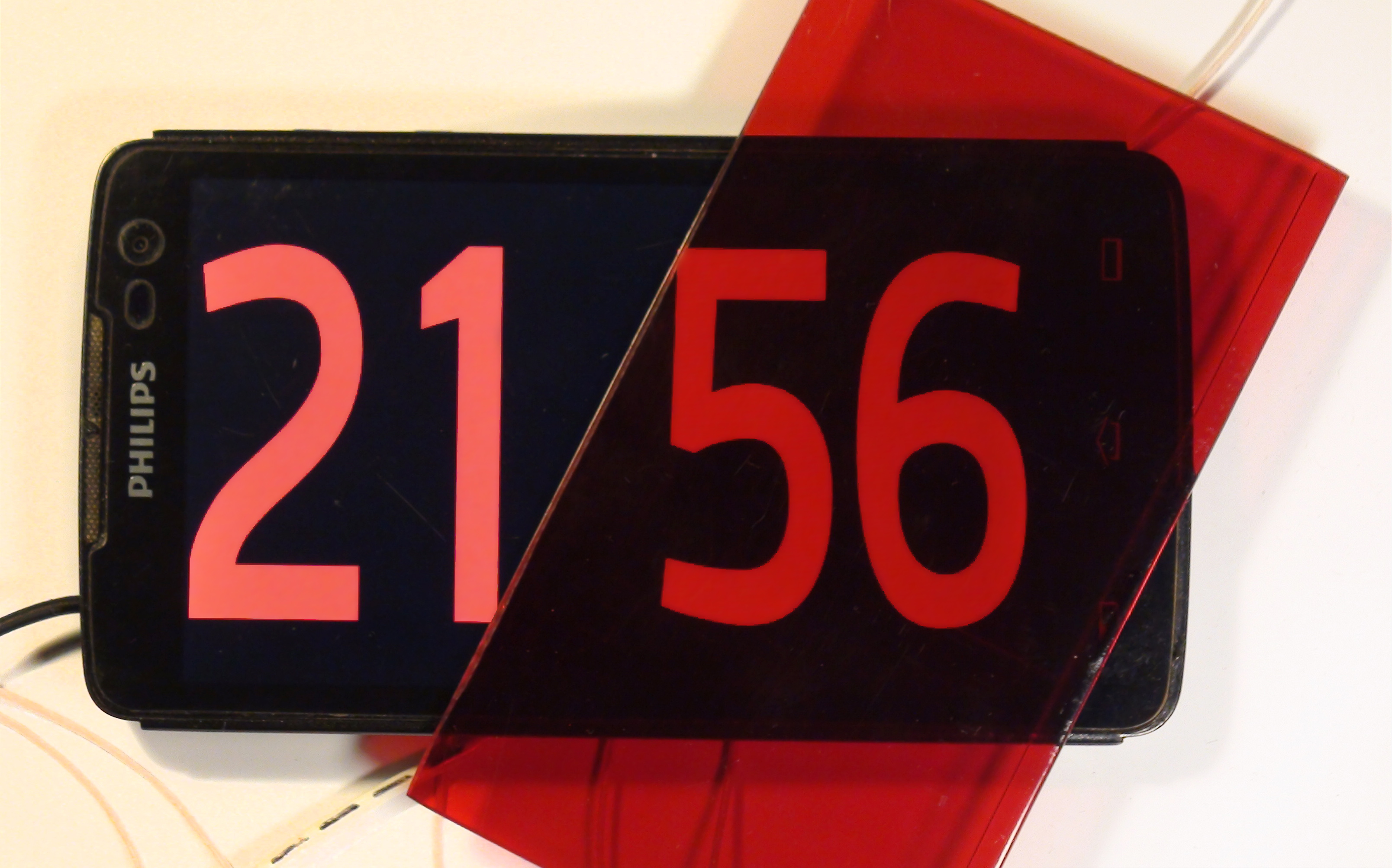
Final touches
In principle, on this the transformation of the old unnecessary mobile phone into excellent beautiful watches can be considered complete.
True, I was confused before the heap by the fact that in the font editor I changed the .otf-font a bit so that the characters were as I wanted, right down to the slightest bends. Trifle, but nice! I also had to make the font monospaced, so that when changing characters, the line did not move out and did not get beyond the display. Used one of open-source font editors, Glyphr Studio.
Well, in the end it remains only to fix the entire structure on a shelf in the corner of the room. There is a lot of room for creativity. I just bent the L-shaped strip of aluminum and gently screwed the back cover of the smartphone with cogs to it. The other end screwed to the shelf. Can be rotated by setting any viewing angle. And slightly bend-straighten aluminum, adjusting the angle vertically. In fact, I generally installed everything, so I don’t touch it anymore.
Backup battery fitted at the bend of the mounting strip. Here I did without the exquisite design, there is nothing visible behind. Also, I did not bother with any terminal containers for the battery, but just carefully soldered directly to the metal case 18650 in those places that do not adjoin the internal contents of the battery in order not to overheat it with a soldering iron.
All connections are made by conventional wiring through the drilled holes in the back of the smartphone. And inside, I just got a little solder straight to the details and tracks of the smartphone board.
In total, two external wires go from the construction: powering 5V from a mains charger and a GPS antenna cable going to the window and glued to the glass with tape.
The clock has been making me happy for almost a year with big beautiful figures, precise progress and uninterrupted reliable work.
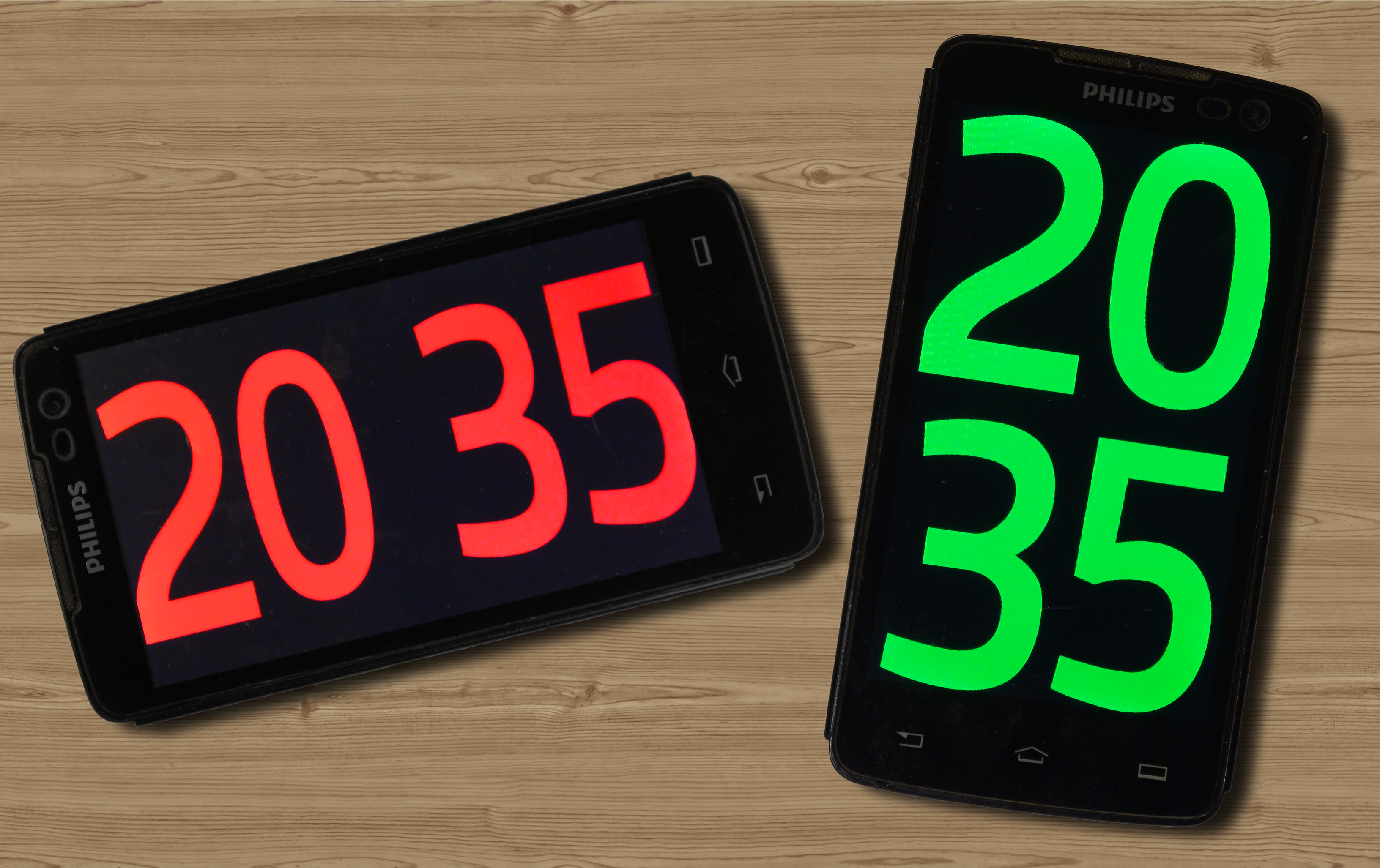
And for fun, I drew the second clock widget - for the vertical position of the smartphone.
Horizontal and vertical clocks on the same scale.
I began to invent it for the reason that with such an unconventional arrangement, the numbers can be made even larger, that is, the useful use of the screen area is obtained as much as possible. In addition, in this case, there is no need to change the character width factor every time when switching from the time format X: XX to XX: XX and back, since everything always fits automatically.
True, almost everyone to whom I showed such non-standard vertical clocks said “fuuu, horizontal is better!”. Well, this thing is an amateur; I personally like both.
That's all. Everyone who read, thank you for your attention!
Source: https://habr.com/ru/post/443052/
All Articles