Rosserial & STM32
The ROS robotic operating system is a fairly powerful platform for creating robotic systems, which includes everything you need to develop your projects from the simplest software components called “nodes” and the data exchange protocol to the simulation environment of the real Gazebo robot platform. ROS is mainly used in conjunction with such microcontrollers on the Arduino platform. Internet is full of all sorts of tutorials about a bunch of ROS and Arduino.
At the moment there is no information about the use of the robotic operating system ROS in conjunction with the STM32 microcontroller. The Internet is full of questions.

To work with STM32, we need STM32CubeMX and SystemworkbenchforSTM32. Information about their installation on the network abound, we will not dwell on this.
')
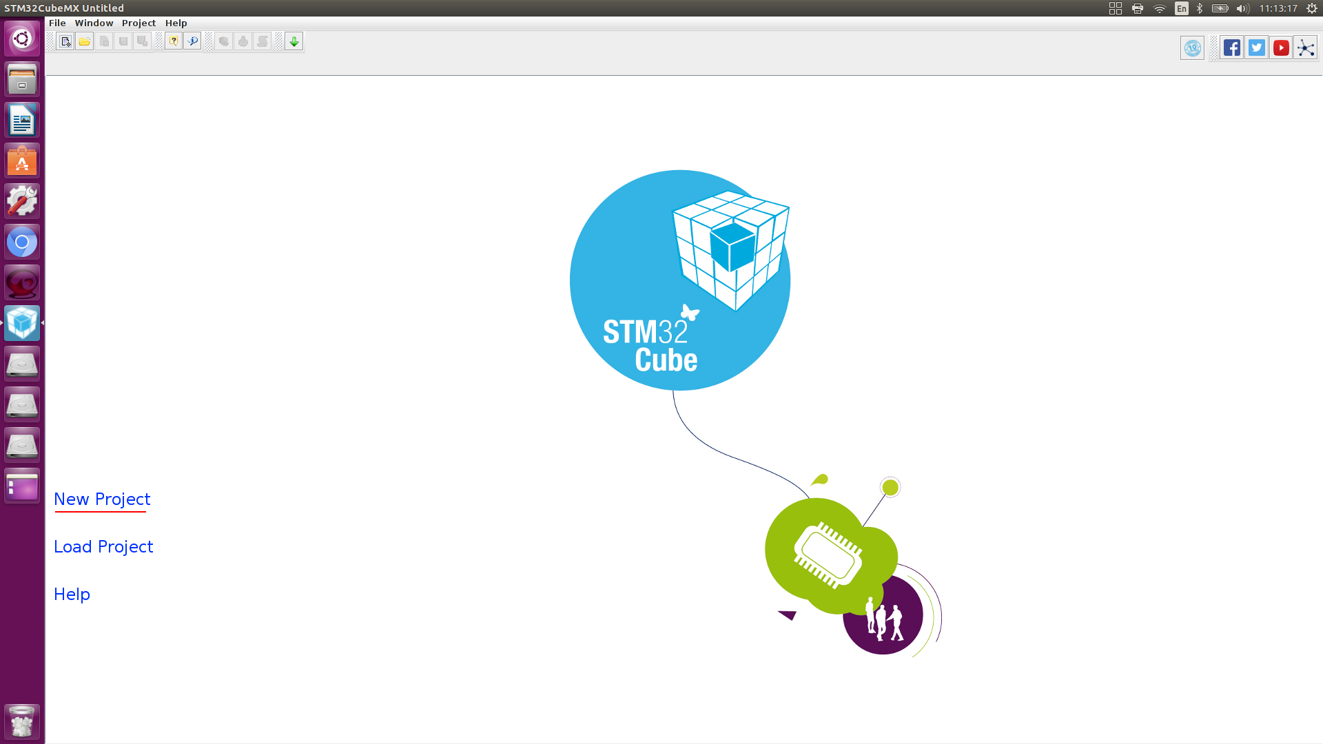
To configure the controller go to the STM32CubeMX
Create a new project.
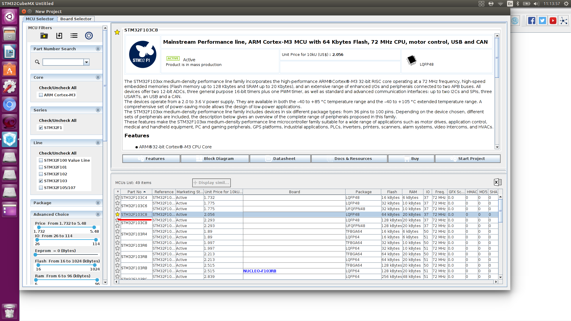
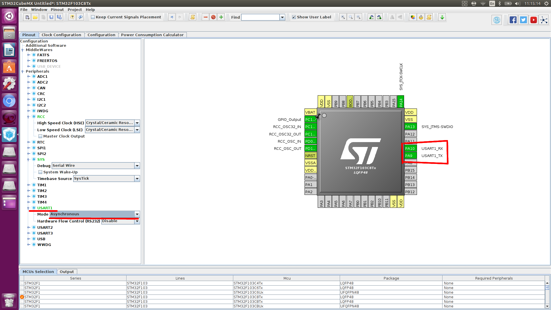
Choose a microcontroller, I have STM32f103c8t6.
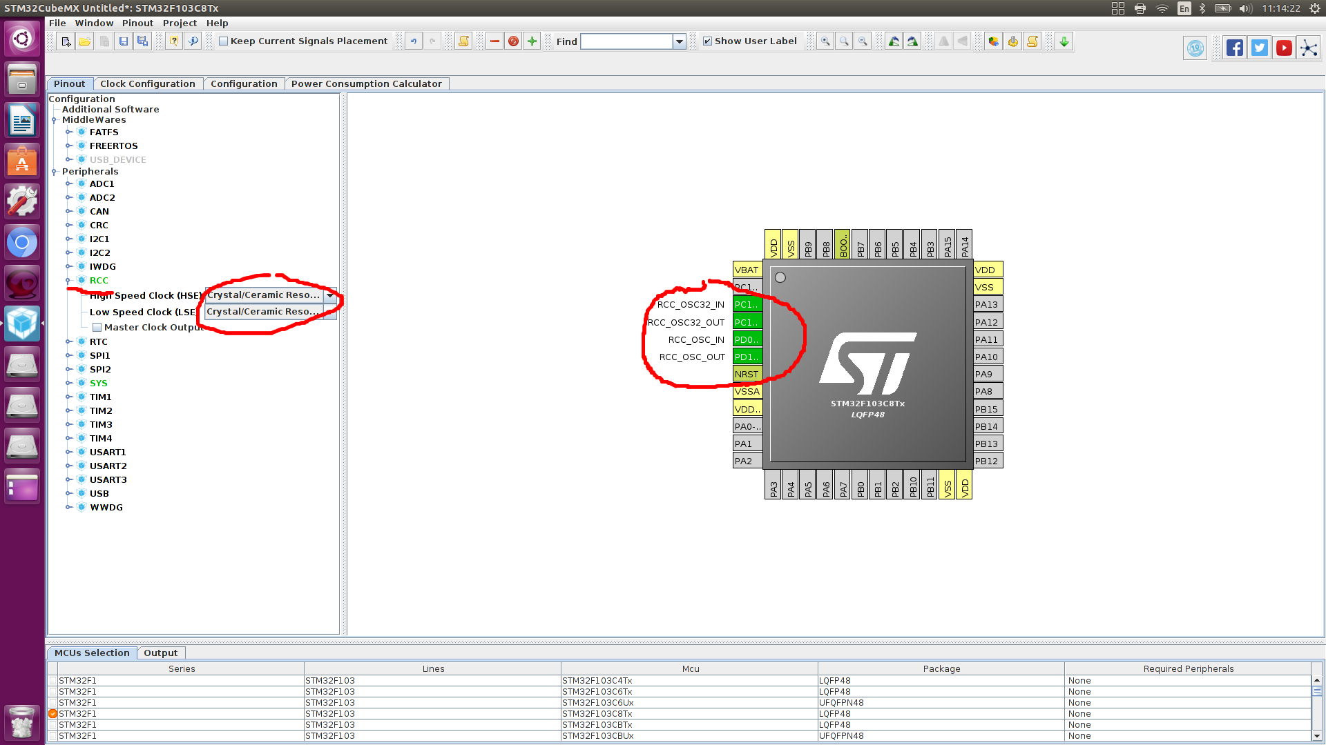
At the periphery, we indicate that the external quartz resonator is connected, we have 2 of them
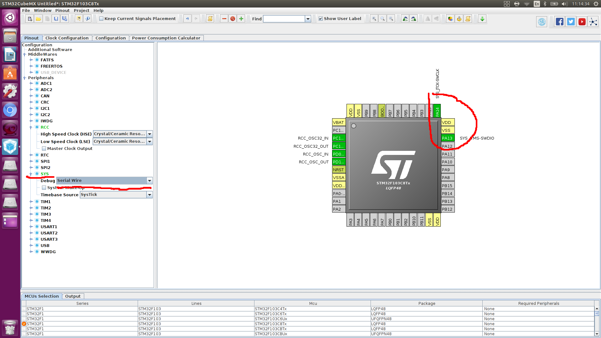
We configure conclusions through which it is possible to include debugging of the controller, (running forward, if the project is in C ++, debugging may not work)
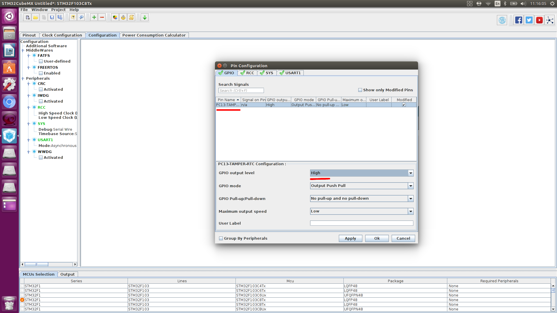
Let's configure the 13 pins of the port C, the built-in LED is connected to it

Configure the UART pins.
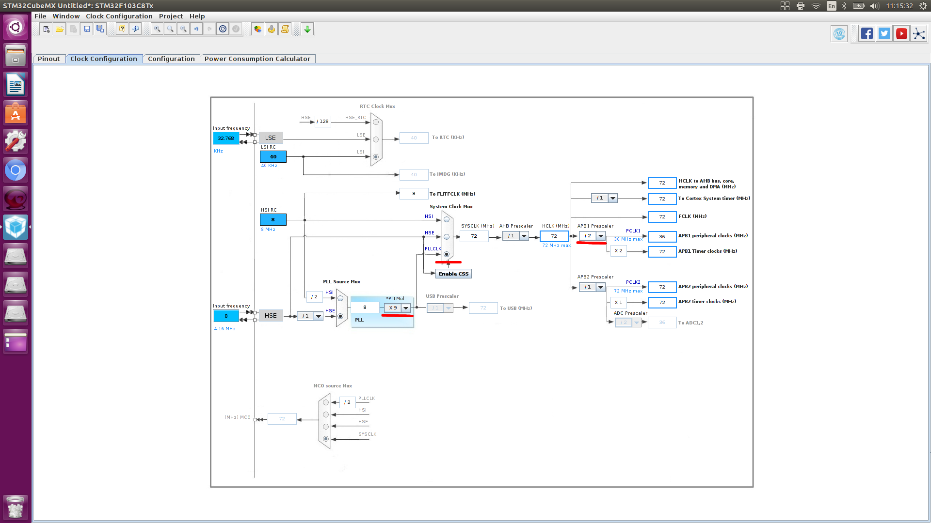
Let's go to lock_configuration and perform the settings as in the picture.
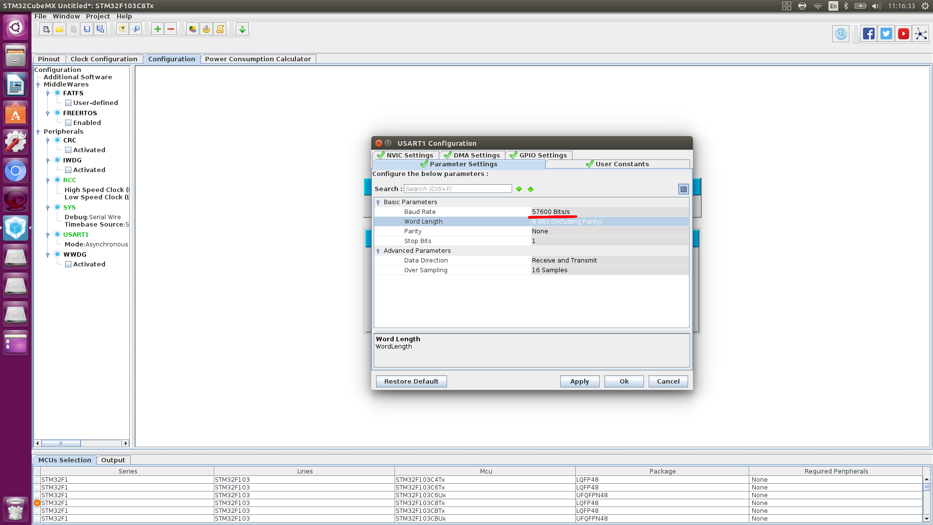
UART
Adjust the speed of data exchange.
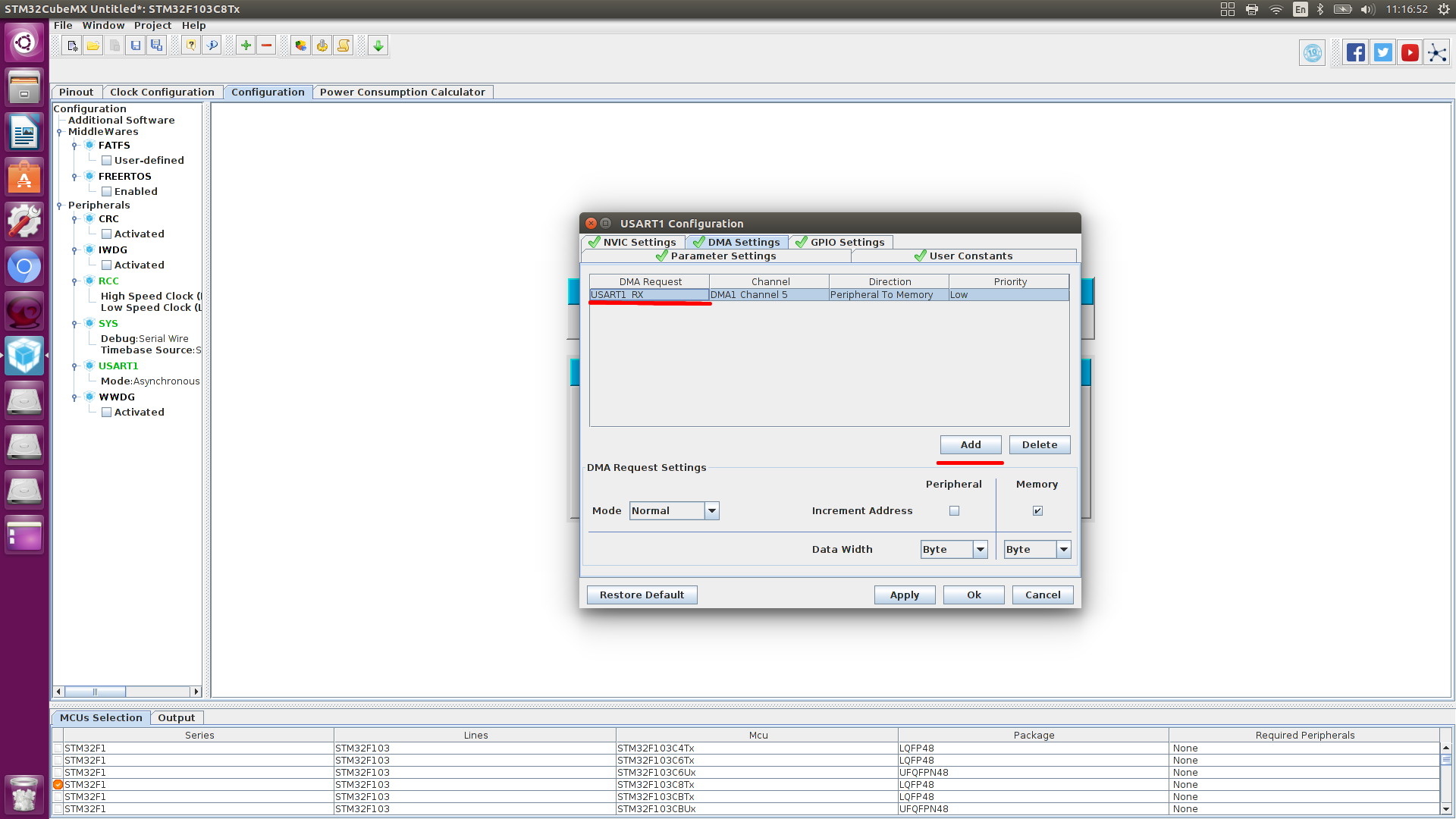
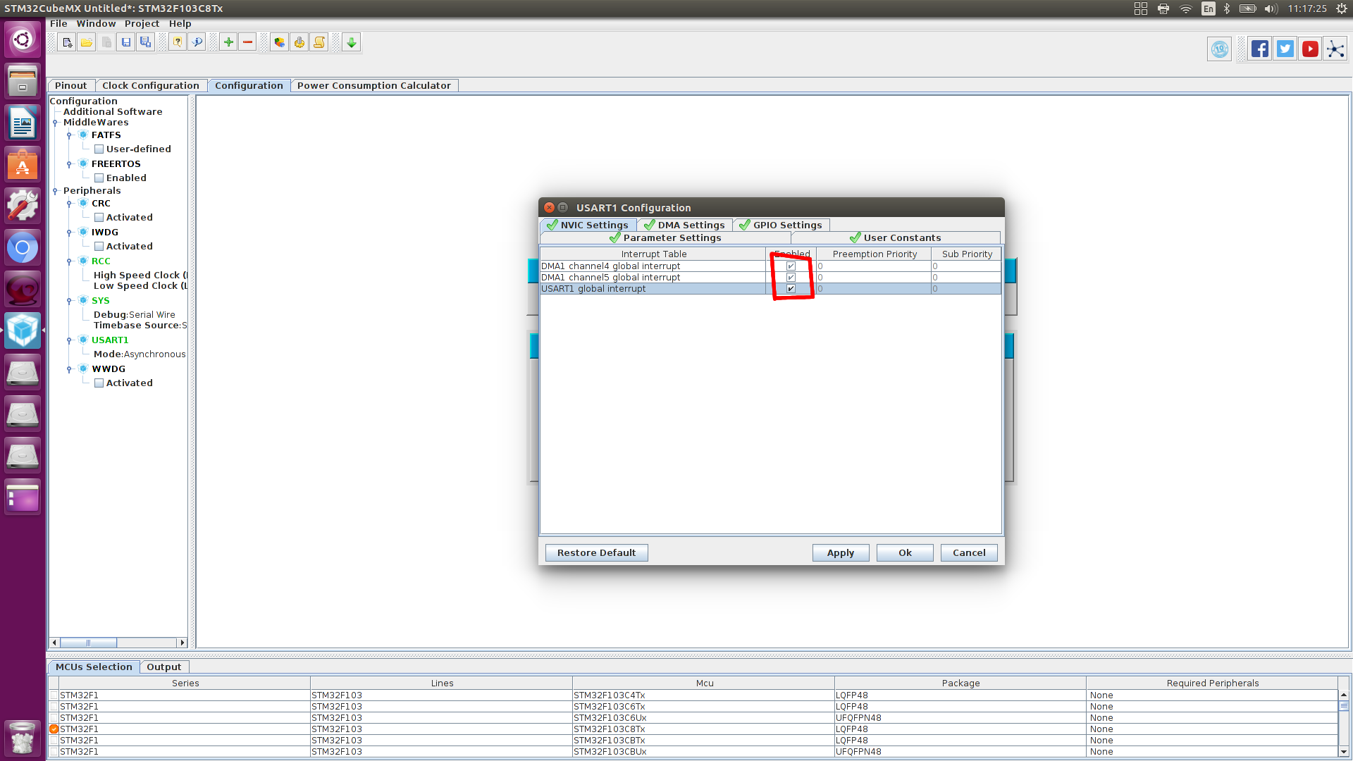
DMA setup.

Setting interrupt, you need to specify a global interrupt UART
We are waiting for you to meet
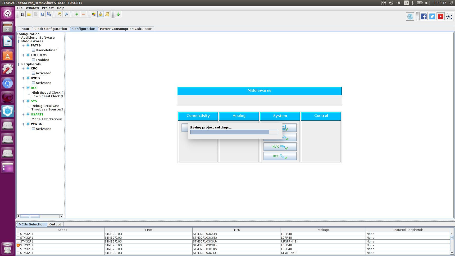
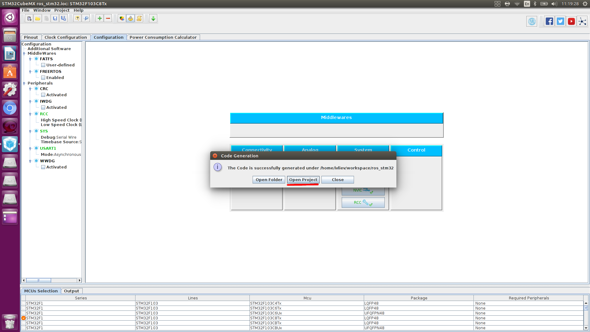
We open the project,
Having opened this project in SW4STM32, adding some peripheral control, collecting it, and flashing the controller, I did not get any result.
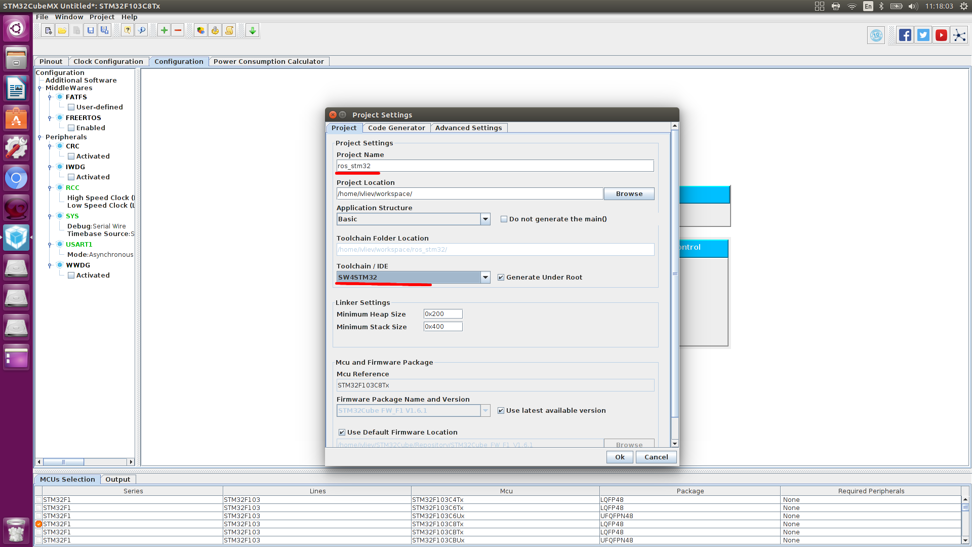
Therefore, we create a new project according to the following instructions, and transfer the configuration obtained by STM32CubeMX.
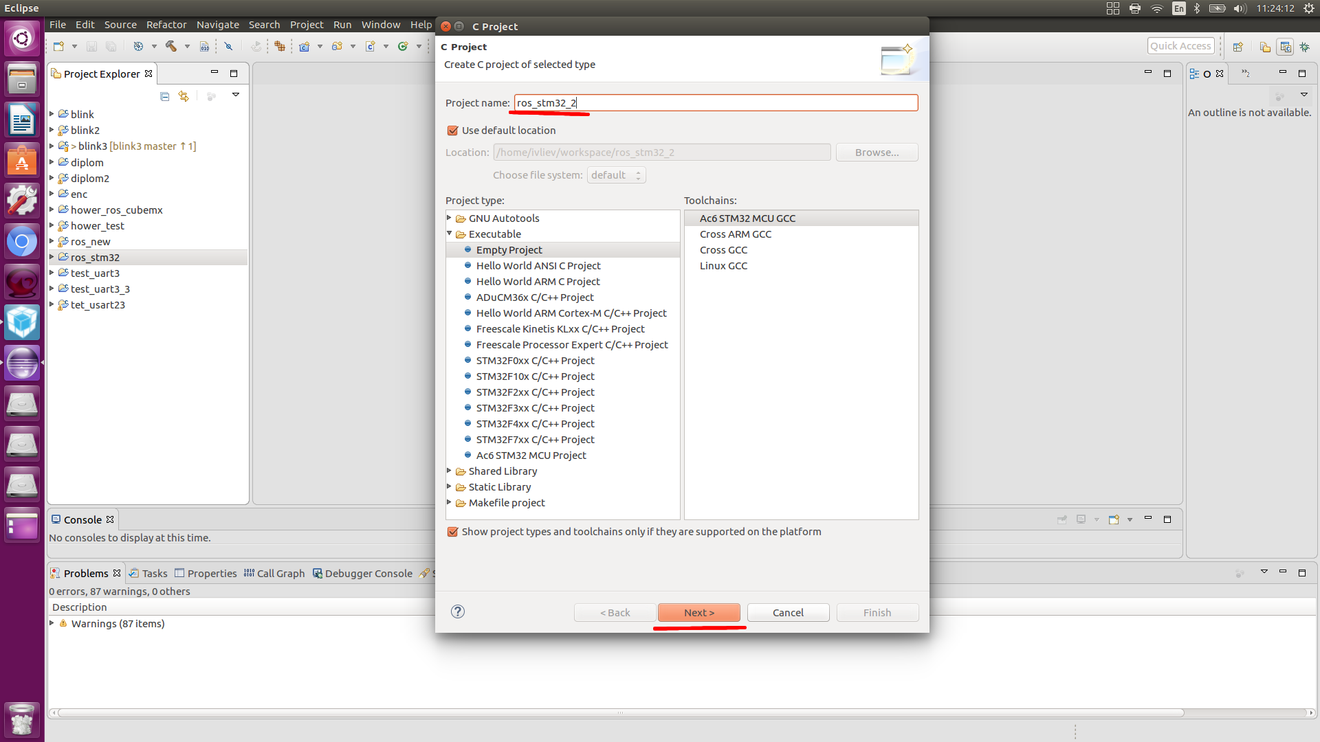
1) Click File> New> C Project
2) C Project
1) Enter project name
2) Select project type: Executable> Ac6 STM32 MCU Project
3) Select Toolchains: Ac6 STM32 MCU GCC
4) Click "Next"
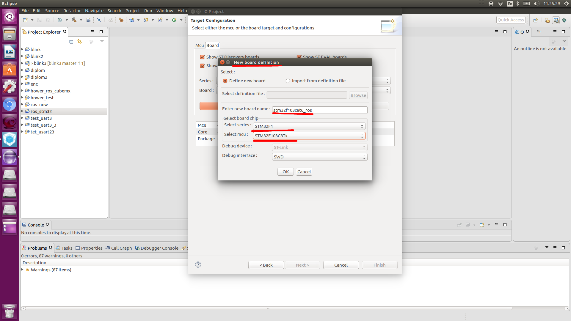
3) Choose a microcontroller
1) Click "Create a new custom board"
1) Save Defining New Board
2) Enter the name of the new board: STM32F103
3) Select board chip: STM32F1
4) Select MCU: STM32F103RCTx
5) Click "OK".
2) Select the board you just created!
1) Select the series: STM32F1
2) Select the board: STM32F103
3) Click "Next"
4) Connect the HAL libraries
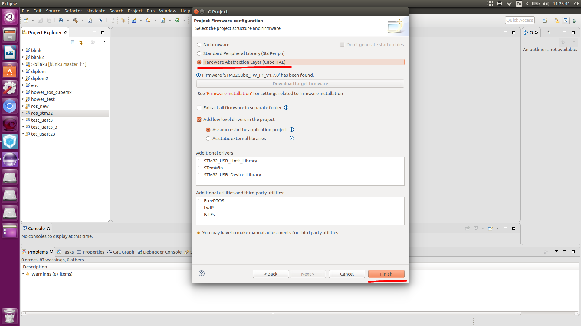
5) Click “Finish”
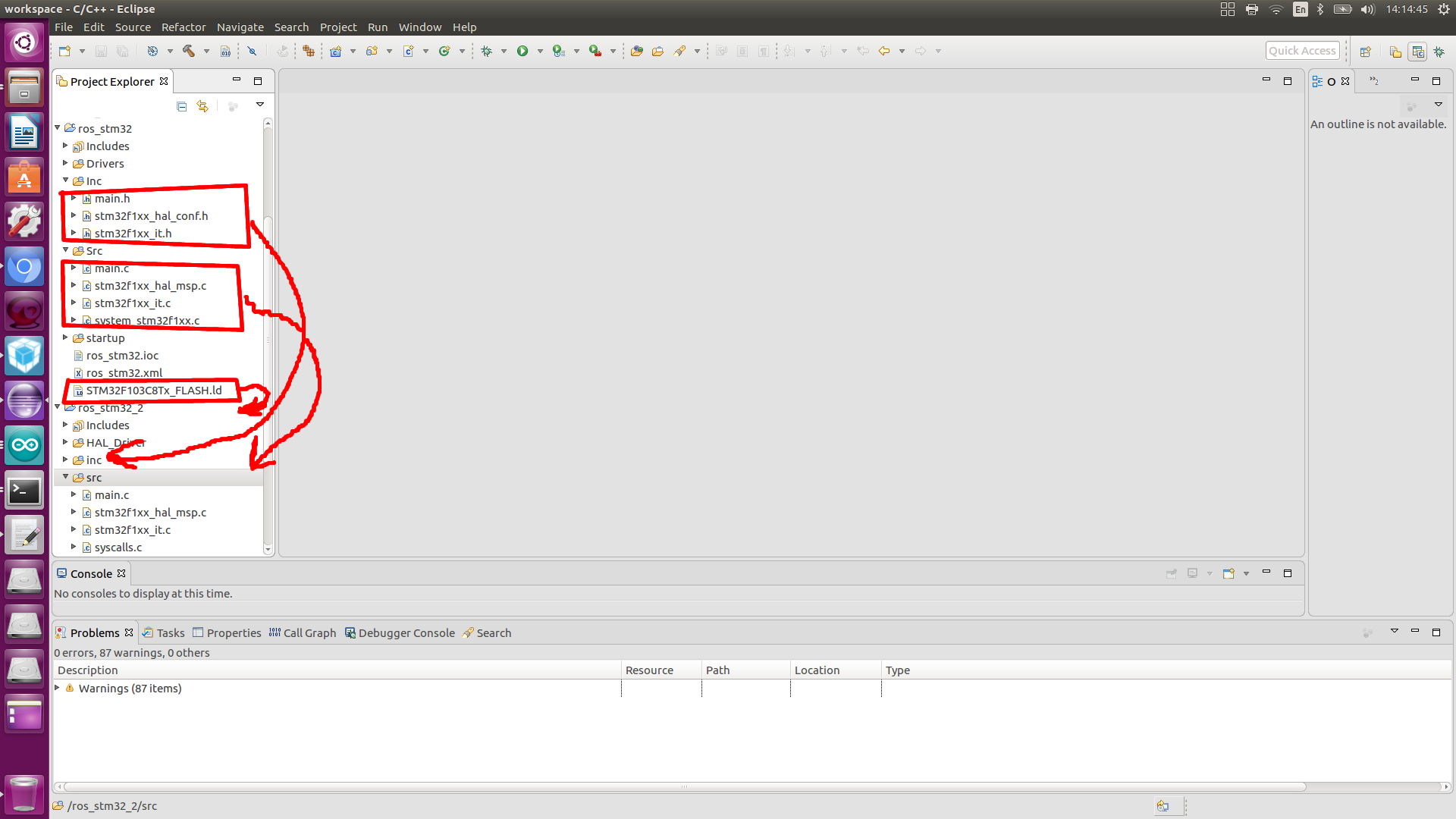
Copy the contents of the src and inc files created by the cube into our files, also copy STM32F103C8Tx_FLASH.ld
To test the performance of the STM32 itself and the code in the while loop, write the following lines
Here we just blink LED.
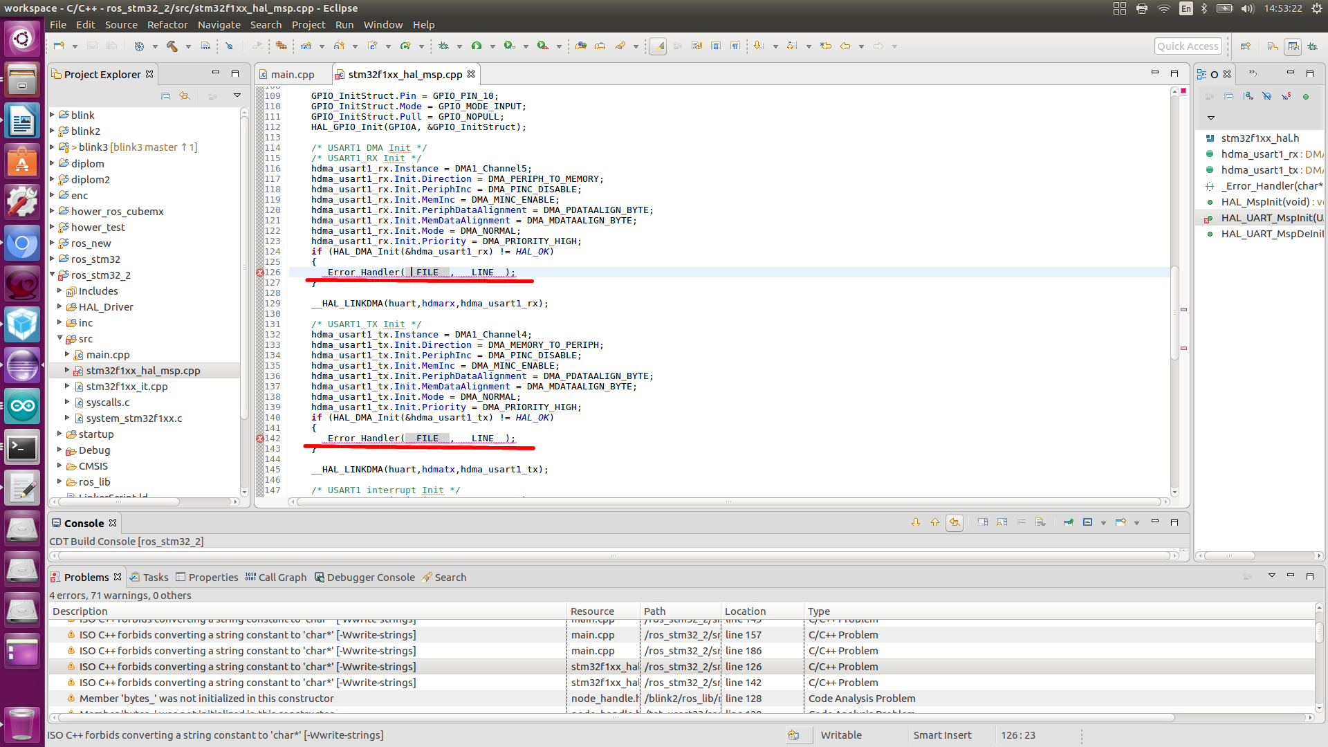
During assembly, problems may occur in the stm32f1xx_hal_msp.c file.
The error associated with the void function HAL_MspInit (void) is fixed as follows.
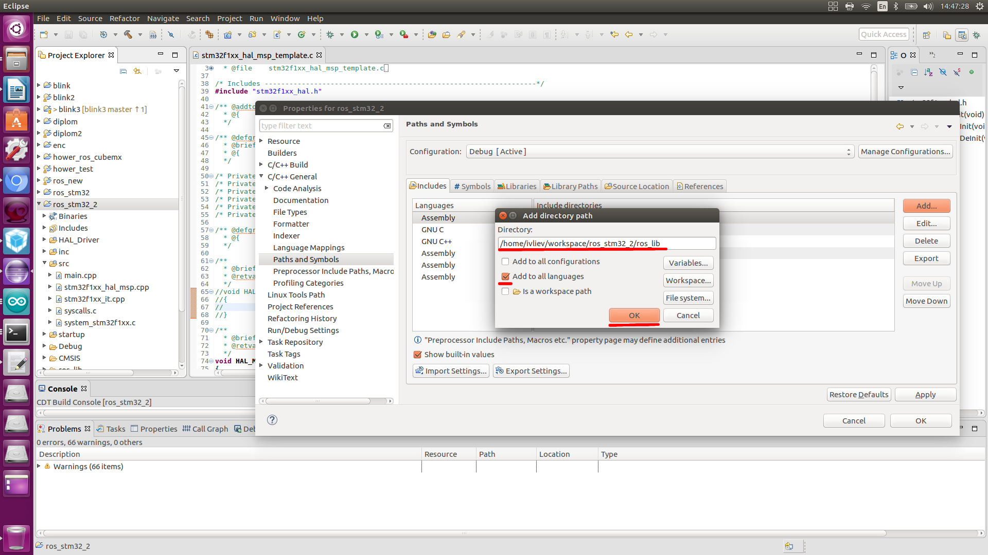
Open the folder with the library HAL_Driver, go to / src open the file stm32f1xx_hal_msp_template.c and comment out the same function:

We collect again (must be assembled without errors)
Forgot to mention for the controller firmware will need the utility st-flash.
Using ST link
Check ST Link Detection:
In response, we should see something like:
For the controller firmware, go to the folder of our project and flash the controller through the following command:
Checked. Everything is working. Moving on.
Since the ROS libraries are written in C ++, we translate our project into a C ++ project, and change the format of the main.c, stm32f1xx_hal_msp.c, stm32f1xx_it.c files to .cpp
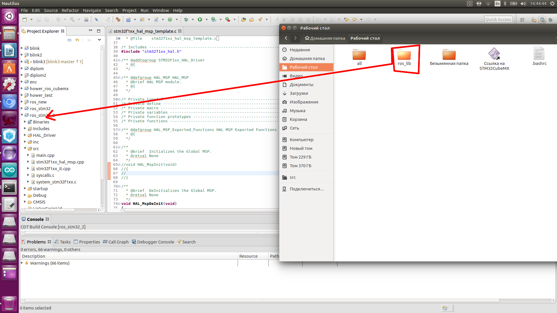
We clone my repository with libraries growing and the right files for rosserial to work on STM32.
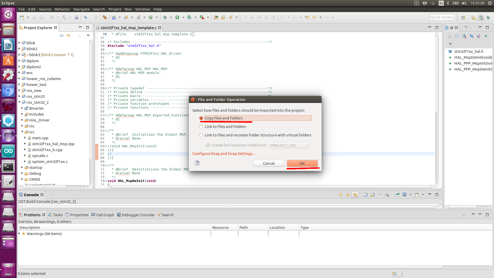
Paste the cloned folder into the project.
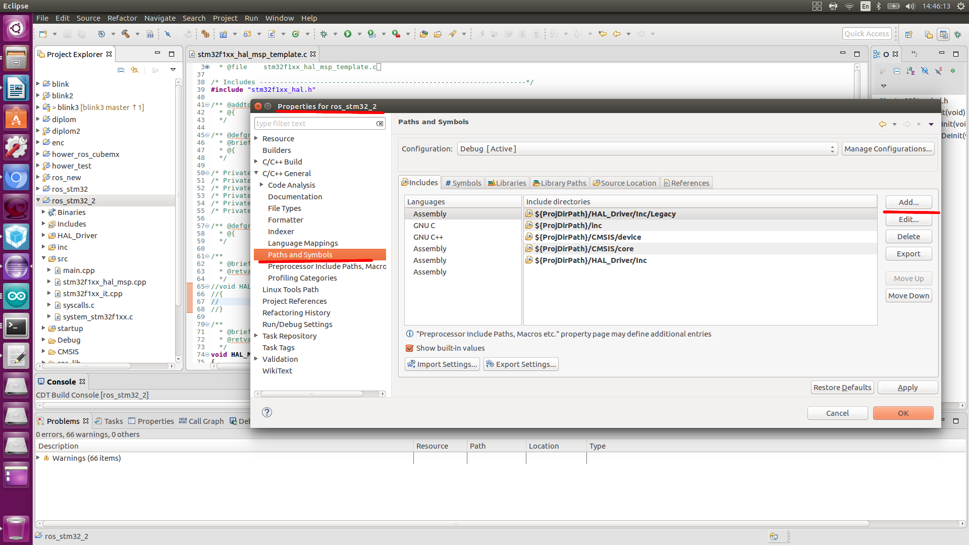
Go to the project settings (Properties), first of all we connect the library, go ...

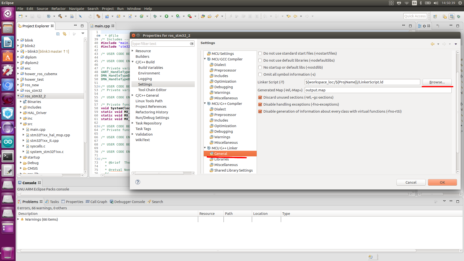
Change the linker

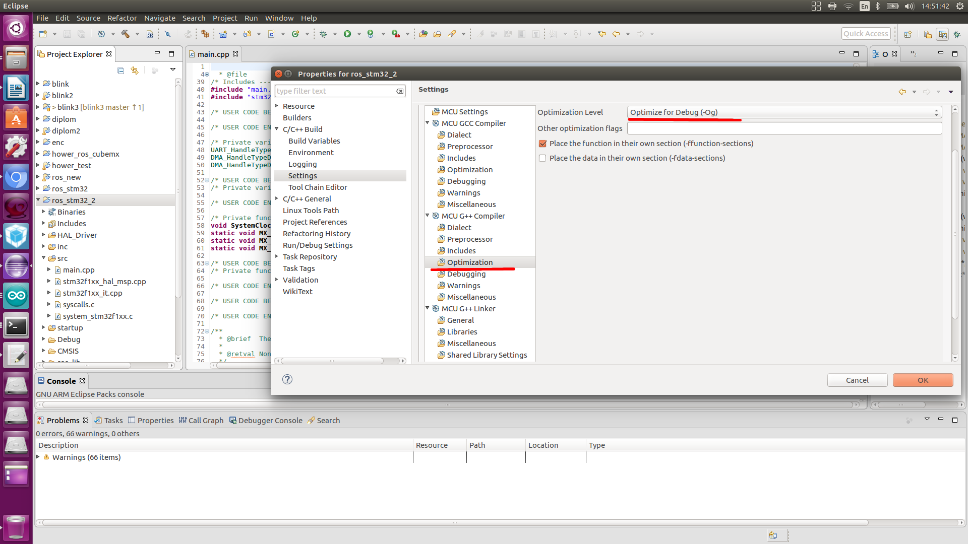
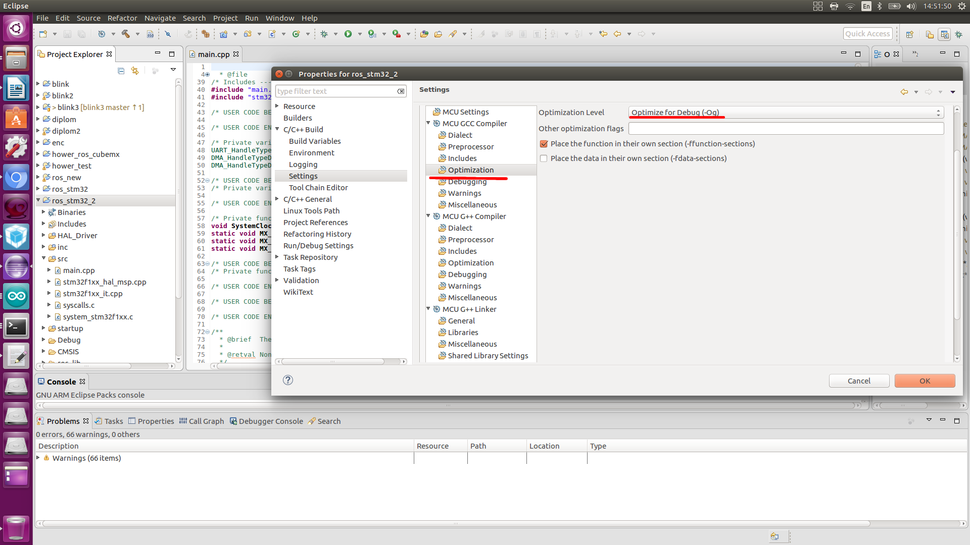
Perform optimization
Well, now let's make some changes to main.cpp, since it is almost empty, the first thing we do is connect the ROS library, and the libraries for interacting with ROS topics, or rather, with the data types of these topics.
Create a node that publishes this topic and accepts
Initialize the node and topics in main.
Also add variables to work with time and what we will publish.
In the while loop, we have the following. We will publish our phrase after a certain time.
We collect the project.
The following errors may appear:


We assemble again and flash it.
Now directly interaction with ROS.
In one terminal we launch ROS.
Next we start the node.
We get the following
Further in a new window of the terminal, we look, topics
We get the following topics:
In the topic chatter controller publishes the phrase.
We can listen to him through the team

Now we will send the data to the led topic.
And we must change the state of the LED.
At the moment there is no information about the use of the robotic operating system ROS in conjunction with the STM32 microcontroller. The Internet is full of questions.
Let's start work
To work with STM32, we need STM32CubeMX and SystemworkbenchforSTM32. Information about their installation on the network abound, we will not dwell on this.
')
To configure the controller go to the STM32CubeMX
Create a new project.
Choose a microcontroller, I have STM32f103c8t6.
At the periphery, we indicate that the external quartz resonator is connected, we have 2 of them
We configure conclusions through which it is possible to include debugging of the controller, (running forward, if the project is in C ++, debugging may not work)
Let's configure the 13 pins of the port C, the built-in LED is connected to it
Configure the UART pins.
Let's go to lock_configuration and perform the settings as in the picture.
Let us turn to a more detailed configuration of the periphery.
UART
Adjust the speed of data exchange.
DMA setup.
Setting interrupt, you need to specify a global interrupt UART
GPIO setup
Customize build project
We are waiting for you to meet
We open the project,
Creating a project under System Workbench For STM32
Having opened this project in SW4STM32, adding some peripheral control, collecting it, and flashing the controller, I did not get any result.
Therefore, we create a new project according to the following instructions, and transfer the configuration obtained by STM32CubeMX.
Creating a project under System Workbench For STM32
1) Click File> New> C Project
2) C Project
1) Enter project name
2) Select project type: Executable> Ac6 STM32 MCU Project
3) Select Toolchains: Ac6 STM32 MCU GCC
4) Click "Next"
3) Choose a microcontroller
1) Click "Create a new custom board"
1) Save Defining New Board
2) Enter the name of the new board: STM32F103
3) Select board chip: STM32F1
4) Select MCU: STM32F103RCTx
5) Click "OK".
2) Select the board you just created!
1) Select the series: STM32F1
2) Select the board: STM32F103
3) Click "Next"
4) Connect the HAL libraries
5) Click “Finish”
Adding Files
Copy the contents of the src and inc files created by the cube into our files, also copy STM32F103C8Tx_FLASH.ld
To test the performance of the STM32 itself and the code in the while loop, write the following lines
HAL_GPIO_TogglePin(GPIOC, GPIO_PIN_13); HAL_Delay(100); Here we just blink LED.
During assembly, problems may occur in the stm32f1xx_hal_msp.c file.
The error associated with the void function HAL_MspInit (void) is fixed as follows.
Open the folder with the library HAL_Driver, go to / src open the file stm32f1xx_hal_msp_template.c and comment out the same function:
We collect again (must be assembled without errors)
Forgot to mention for the controller firmware will need the utility st-flash.
$ sudo apt-get install cmake $ sudo apt-get install libusb-1.0.0 $ git clone github.com/texane/stlink.git $ cd stlink $ make release $ cd build/Release; sudo make install $ sudo ldconfig Using ST link
Check ST Link Detection:
$ st-info —probe In response, we should see something like:
Found 1 stlink programmers serial: 563f7206513f52504832153f openocd: "\x56\x3f\x72\x06\x51\x3f\x52\x50\x48\x32\x15\x3f" flash: 262144 (pagesize: 2048) sram: 65536 chipid: 0x0414 descr: F1 High-density device For the controller firmware, go to the folder of our project and flash the controller through the following command:
cd workspace/ros_stm32_2/ st-flash write Debug/ros_stm32_2.bin 0x8000000 Checked. Everything is working. Moving on.
Since the ROS libraries are written in C ++, we translate our project into a C ++ project, and change the format of the main.c, stm32f1xx_hal_msp.c, stm32f1xx_it.c files to .cpp
We clone my repository with libraries growing and the right files for rosserial to work on STM32.
git clone https://gitlab.com/ivliev123/ros_lib Paste the cloned folder into the project.
Go to the project settings (Properties), first of all we connect the library, go ...
Change the linker
Perform optimization
Well, now let's make some changes to main.cpp, since it is almost empty, the first thing we do is connect the ROS library, and the libraries for interacting with ROS topics, or rather, with the data types of these topics.
#include <ros.h> #include <std_msgs/String.h> #include <std_msgs/UInt16.h> Create a node that publishes this topic and accepts
void led_cb( const std_msgs::UInt16& cmd_msg){ HAL_GPIO_TogglePin(GPIOC, GPIO_PIN_13); } ros::NodeHandle nh; std_msgs::String str_msg; ros::Publisher chatter("chatter", &str_msg); ros::Subscriber<std_msgs::UInt16> sub("led", led_cb); Initialize the node and topics in main.
nh.initNode(); nh.advertise(chatter); nh.subscribe(sub); Also add variables to work with time and what we will publish.
const char * hello = "Hello World!!"; int chatter_interval = 1000.0 / 2; int chatter_last = HAL_GetTick(); In the while loop, we have the following. We will publish our phrase after a certain time.
if (nh.connected()) { if(HAL_GetTick() - chatter_last > chatter_interval) { str_msg.data = hello; chatter.publish(&str_msg); chatter_last = HAL_GetTick(); } } nh.spinOnce(); We collect the project.
The following errors may appear:
We assemble again and flash it.
Now directly interaction with ROS.
In one terminal we launch ROS.
roscore Next we start the node.
rosrun rosserial_python serial_node.py /dev/ttyUSB0 We get the following
[INFO] [1551788593.109252]: ROS Serial Python Node [INFO] [1551788593.124198]: Connecting to /dev/ttyUSB0 at 57600 baud [INFO] [1551788595.233498]: Requesting topics... [INFO] [1551788595.258554]: Note: publish buffer size is 2048 bytes [INFO] [1551788595.259532]: Setup publisher on chatter [std_msgs/String] [INFO] [1551788595.275572]: Note: subscribe buffer size is 2048 bytes [INFO] [1551788595.276682]: Setup subscriber on led [std_msgs/UInt16] Further in a new window of the terminal, we look, topics
rostopic list We get the following topics:
/chatter /diagnostics /led /rosout /rosout_agg In the topic chatter controller publishes the phrase.
We can listen to him through the team
rostopic echo /chatter Now we will send the data to the led topic.
rostopic pub /led std_msgs/UInt16 "data: 0" And we must change the state of the LED.
Source: https://habr.com/ru/post/443022/
All Articles