Alteration of the IBM 5150 Model A 230 V computer power supply unit

What to do if you suddenly have a beautiful vintage IBM 5150? First of all - do not rush to turn it on, but look at the power supply, which may be 115 volts . And then you have to fence such a thing:
')
But the retrocomputer Matt Millman decided to “teach” this stylish power supply unit to operate from 230 V without additional devices. I’ll give a disclaimer right away: since the alteration concerns the primary side of the block, if you don’t have this ... well, retrocomputing is so multifaceted that there will be another interesting occupation for you, even more complicated. old_gamer , for example, for the same 5150 new motherboard assembled. Therefore, I do not put the Tutorial checkbox.
BP turned out to be pulsed and single-ended - like modern ones:
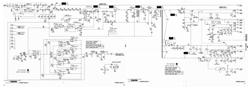
5000 pixels wide image
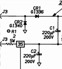
There are other options for the block scheme, but their differences from the base are insignificant. But the main thing - he has a doubler at the entrance. The entire primary side is powered by two series-connected capacitors, the total voltage of which is 325 V. In general, everything is like in a 230-volt power supply unit, only instead of the input bridge is a doubler:
After talking about this on the forum , the author found out that there is also a 230-volt version of this power supply, but there the entire primary side is very different. Therefore, he decided to come up with his own way of reworking, in which he would not have to “plow” half of the board along and across.
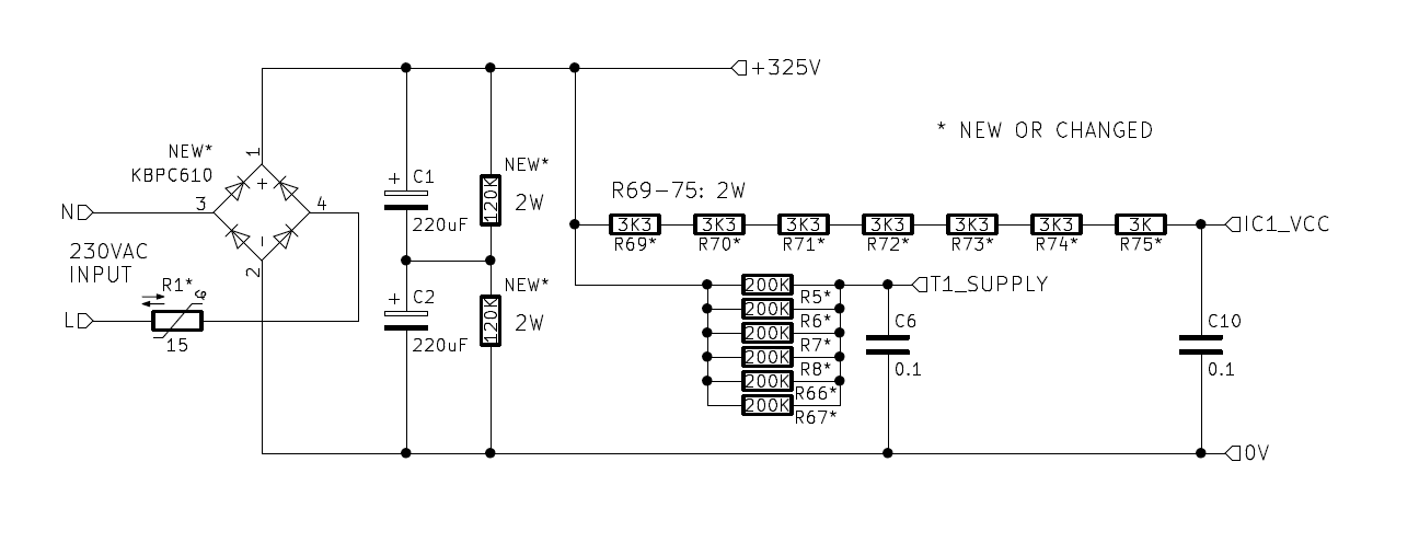
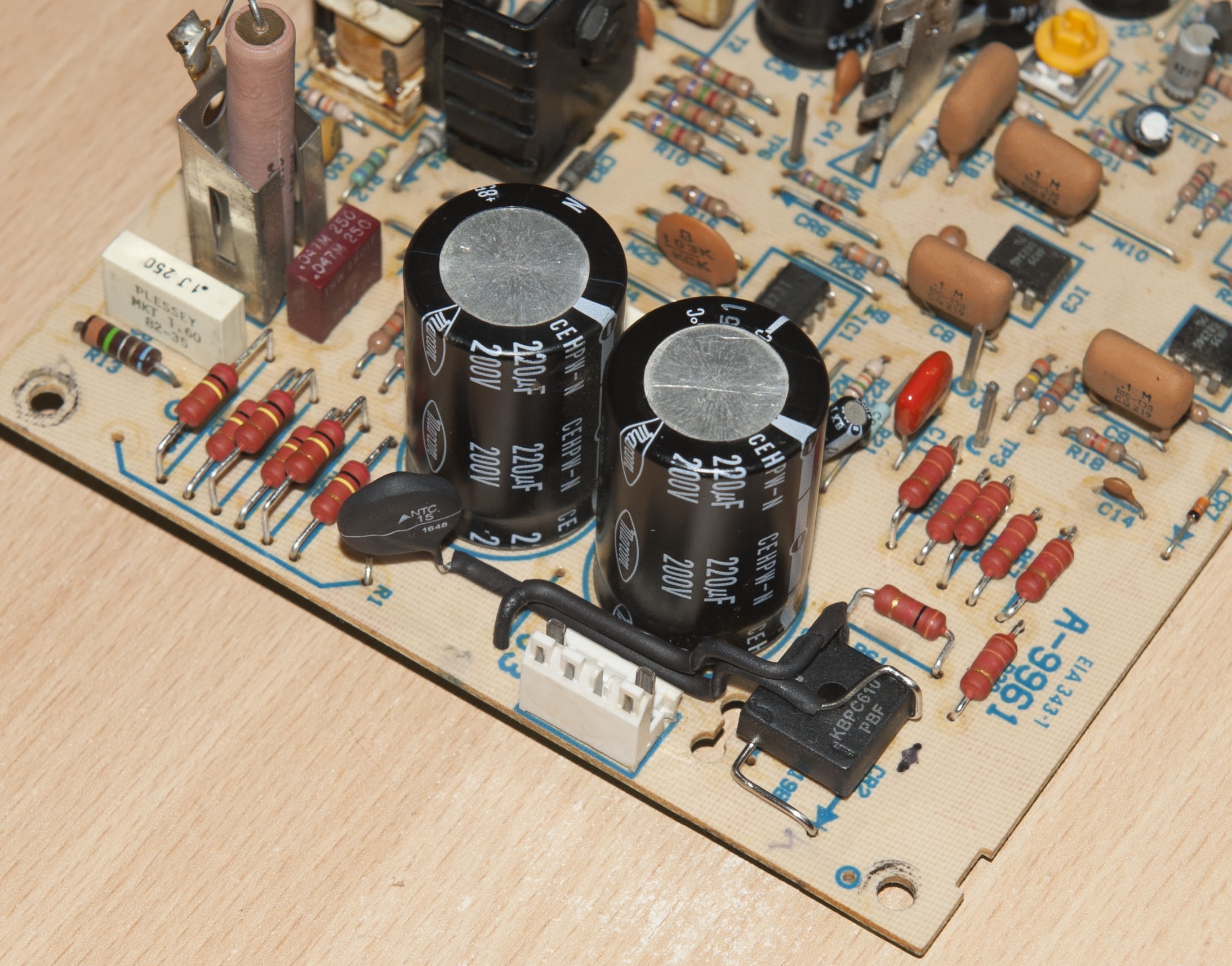
He decided to replace the doubler with bridge KBPC610, at the same time installing a thermistor with a negative temperature coefficient instead of resistor R1. He even modeled how the starting current would decrease as a result:

Many more modern power supply units have switches to choose between a doubler and a bridge. Here is not so simple. An additional load hangs on capacitor C2, so the voltage distribution on capacitors C1 and C2, after replacing the doubler to bridge, will be uneven, and C1 will burst.
From the midpoint, through a long chain of resistors R69 - R75, IC1 of type NE5560 is powered with an integrated Zener diode for voltage of 21.4 V. In order for the load on capacitors C1 and C2 to become uniform, you need to increase the total resistance of the resistor circuit and feed it from the positive terminal of C1 .

With the resistors indicated in the circuit (6 pieces of 1.5 kΩ and 1 piece of 750 ohms), the current through them and the built-in zener diode of the chip will be 14 mA:
(162 V - 22.9 V) / 9750 Ohm = 0.014 A = 14 mA
After transferring the power point of the chain, its total resistance will have to be increased to:
(325V - 22.9 V) / 0.014 A = 21578 Ohms = 21.5 kΩ
But the author had such a power supply, where all 7 resistors are 1.5-kilohm, so the current will be:
(162 V - 22.9 V) / 10500 ohm = 0.0123 A = 13 mA
After reworking the resistance of the chain should be:
(325 V - 22.9 V) / 0.0123 mA = 22886 Ohm = 22.8 kΩ
The next task is to do something with a control point 36. The voltage arrives at it from two places: from the bottom according to the output circuit of the 100-kilohm resistor R9 and from the bottom output of the “fumigator” of six parallel-connected 100-kilohm resistors R5, R6 , R7, R8, R66, R67.

Nothing needs to be done with R9, but all the fumigator resistors will have to be replaced by 200 kilo-ohm ones, since the top pin of this will also be transferred to the plus of the C1 capacitor. The current at the same time will remain equal to 7 - 8 mA, as in the case of power from 115 V to the remake.
Now, parallel to each of the capacitors C1, C2, it is necessary to connect a 120 kΩ, 2 W resistor, this will exactly equalize the voltage across them despite the variation of the parameters. If you, reading all this, fell asleep from boredom, wake up. For now the same thing, only briefly and capaciously. It was like this:

And it became so:
Here is the board before rework:
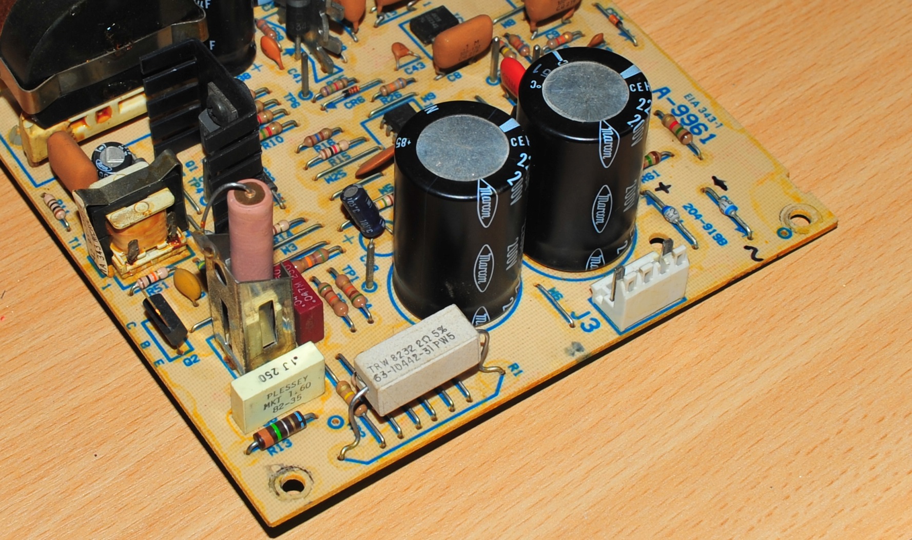

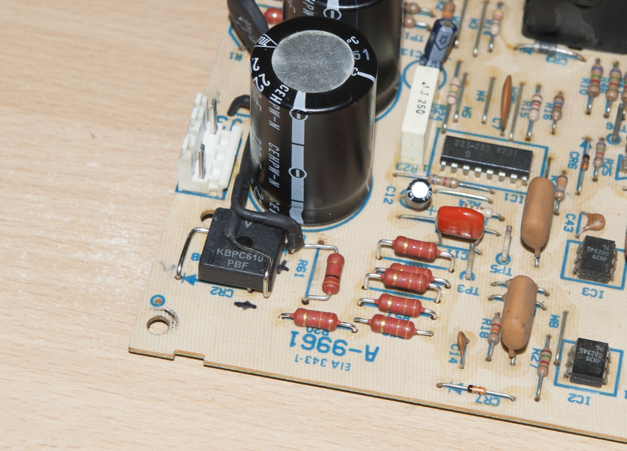
Here after:
Even Kokovin (yes, there, even Pikachu062), looking at this, would say that “out-of-Ethicity” is almost not broken.
For jumpers used hard wire with a diameter of 1 mm (in fact, usually for the wires do not indicate the diameter, and section), placed in heat shrinkage.
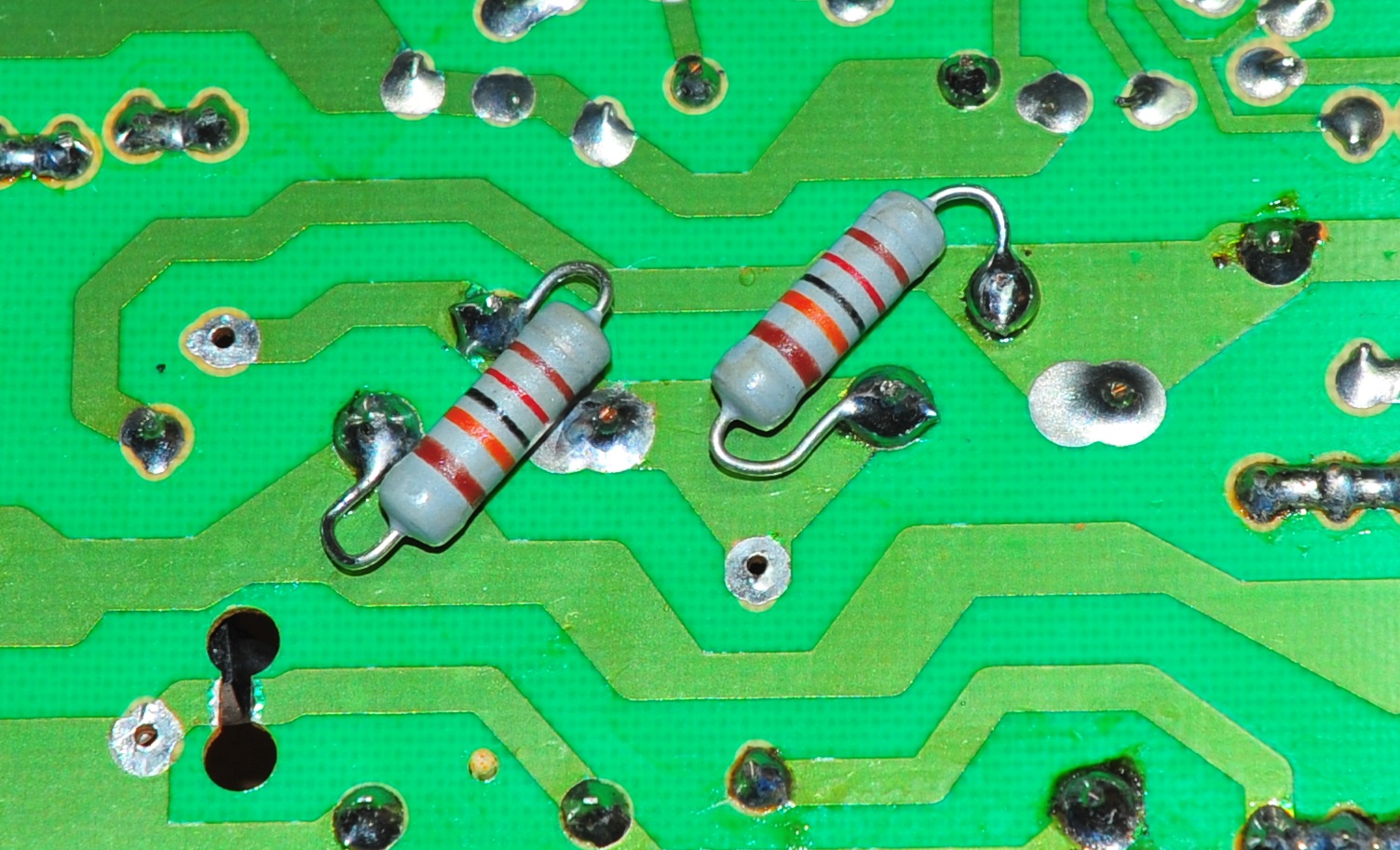
120-kilohm resistors connected in parallel with capacitors are soldered to the back of the board. They should not touch the board or the case!
Now it’s time to rework the noise filter. There were capacitors rated for 125 V (for such capacitors, the effective value of voltage is often indicated not of amplitude):

They had to be replaced with the same, but 250-volt, type Kemet PHE844RD6100MR30L2. And the resistance of the resistor discharging them after switching off is increased from 300 to 560 kΩ.
Can I include? No matter how wrong! Again, remember Pikachu062 with its catchphrase: “it burns without a cooler”. And here the cooler will burn itself (if it is, in some of these power supplies it is not there at all). Because then the fans in the power supply unit were fed not by a constant from the output, but by a switch from the input. Recall BP "Electronics-60", there is the same.
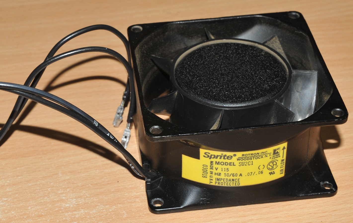
In general, it is necessary to replace the 115-volt fan with a 230-volt fan, retaining the original rare Molex 90331 connector. The improvised tool from the trimmed hanger helped to pull the contacts out of the original connector:
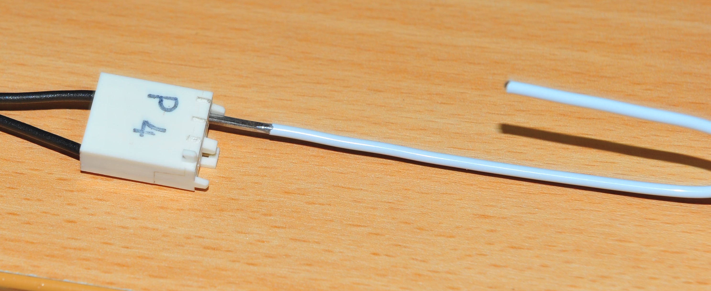
New ones could not be found, on the Molex website it is said that others, like KK .156 (KK396) , will fit this connector.
The original Rotron fan “Sprite” SU2C1 has not been discontinued until now:
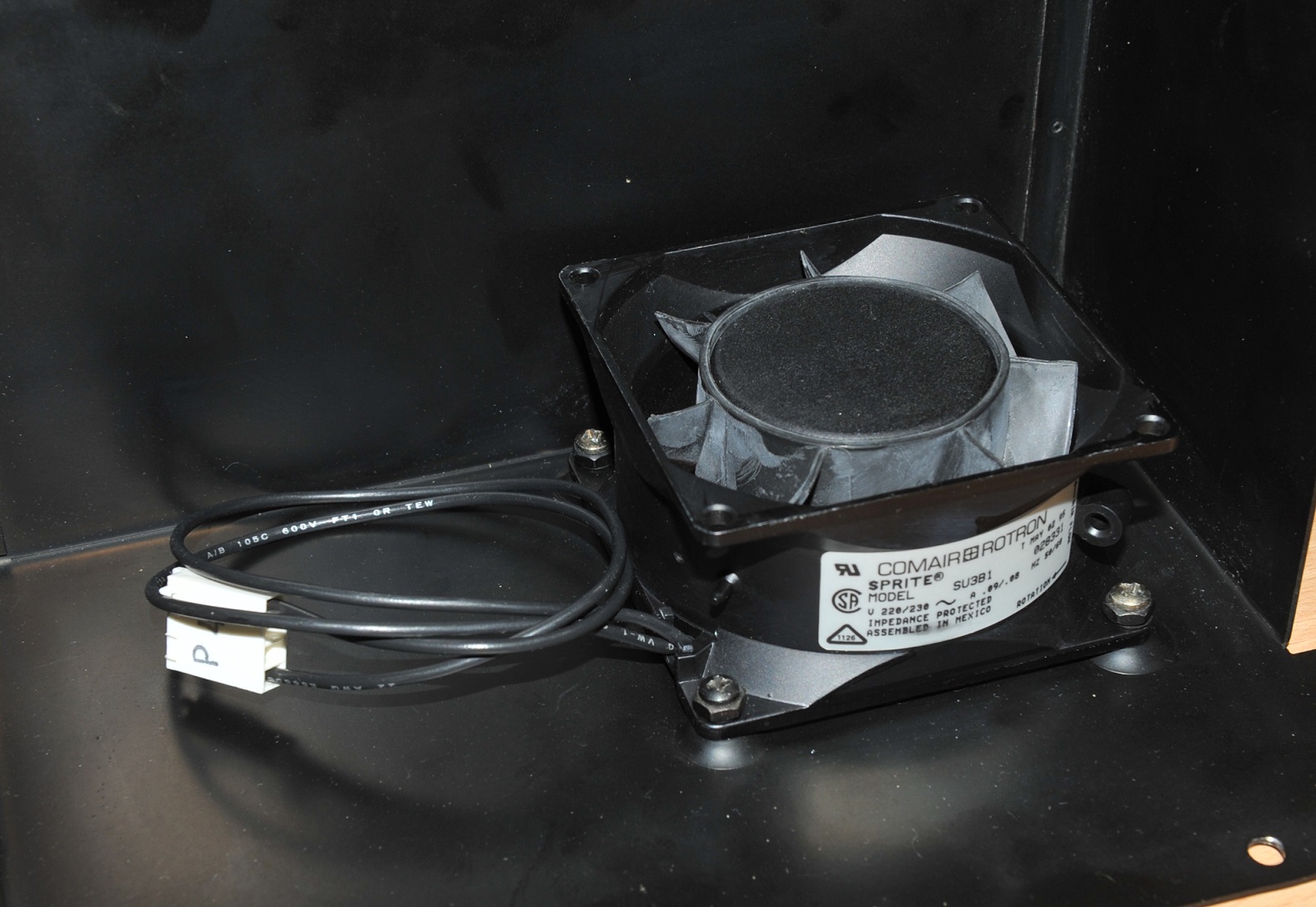
I had to replace it with SU3B1, differing only in the supply voltage, and rearrange the original connector with new contacts:
EBM PAPST 8556N is also suitable:
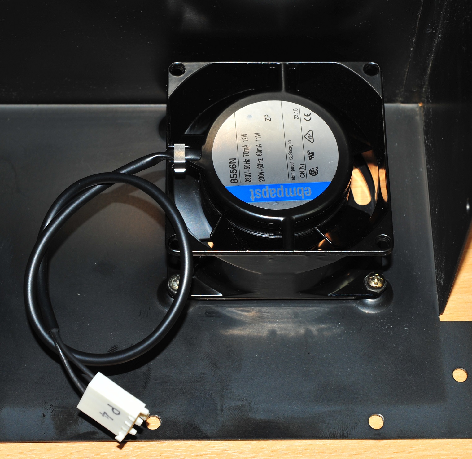
But it blows in the other direction, so it will have to be deployed accordingly.
In those years, pulsed power supply units were designed so that they cannot be switched on without load. But if you really want, then it is possible through a 40-watt incandescent lamp and quite a bit. During this time, you can have time to check (again I remind you that you are working with the primary party):
- voltage at the midpoint between the filter capacitors - must be equal to half the amplitude value of the mains voltage
- voltage from 21 to 22 V at pin 1 of IC1
- current in 10 - 12 mA through a series circuit (connect a milliammeter in advance)
- current of 7-8 mA through the "fumigator" (see the previous paragraph)
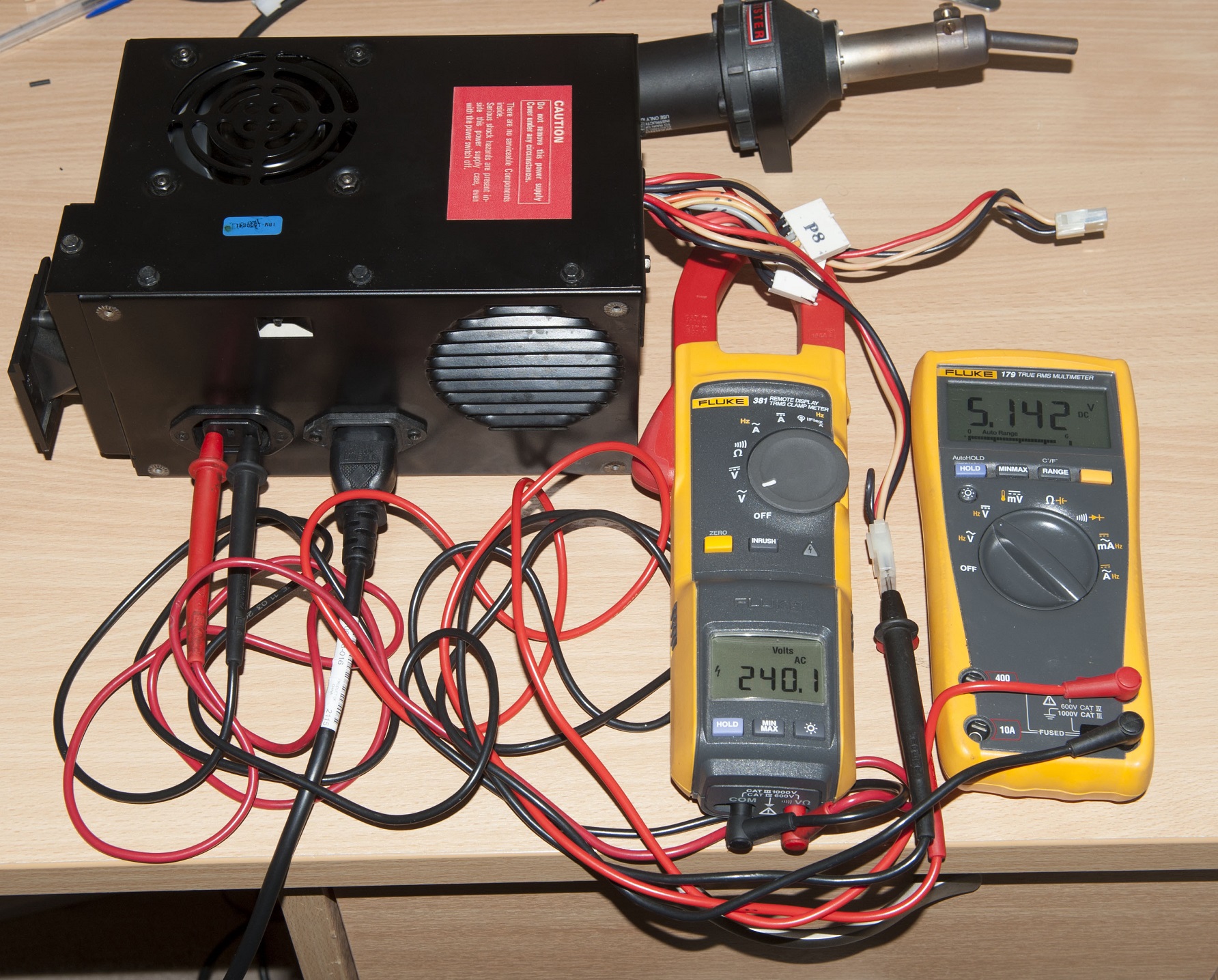
Then the author removed the 40-watt light bulb from the primary circuit, and the output of the PSU loaded the 40-watt equivalent load and "drove" a few hours:
And returned the power supply to the computer. After that, one oddity was discovered: a squeaking sound that disappears after a slight increase in load at the +12 V output. By connecting the oscilloscope to the +5 V output, the author discovered this:
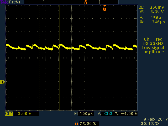
This has lost the EPS electrolytic capacitors on the secondary side. After replacing them, the problem disappeared, and everything works as it should.
Thank you all for your attention. And do not fill 5150 boards over measure, the output power of the PSU there is only 63 watts.
Source: https://habr.com/ru/post/442984/
All Articles