Create your own game controller
Source of inspiration
At game shows, developers of Objects in Space showed a demo of their game with a controller on the cockpit of a huge spacecraft. It was supplemented with illuminated buttons, analog instruments, status lights, switches, etc ... This greatly affects the immersion in the game:

On the game site laid out tutorial on Arduino with a description of the communication protocol for such controllers.
I want to create the same for my game
')
In this example, I’ll spend about $ 40 to add beautiful, big, and heavy switches to the cockpit of a racing simulator. The main costs are connected with these switches - if I used simple switches / buttons, the price was two times lower! This is real equipment capable of withstanding 240 watts of power, and I will only use about 0.03 watts of it.
Warning: I decided to save, so leave a link to a cheap Chinese website, where I buy a bunch of different components / tools. One of the drawbacks of buying components for cheap is that they often have no documentation, so I will solve this problem in the article.
Main components
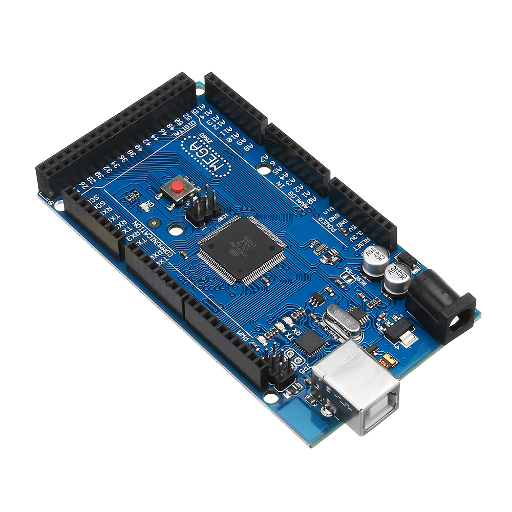
- Arduino Mega2560 - $ 9
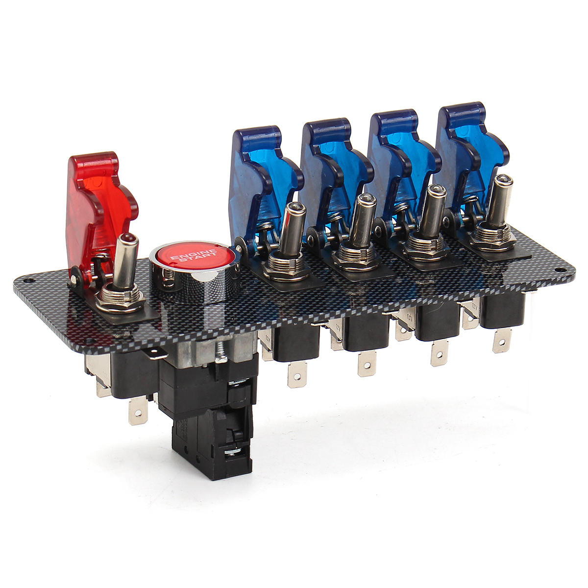
- Ignition Switch Racing Panel - $ 26
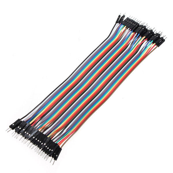
- A bunch of connecting wires ( "male to male" , "male to female" , etc ...) - $ 2
Recommended tools
- Soldering iron ( it is worth choosing a good one , but cheap work can do it )
- Solder ( with rosin 60/40 - it is easy to work with it, although it is harmful to the environment .)
- Shrink tube ( and industrial hair dryer, hair dryer or cigarette lighter ) or electrical tape
- Glue gun ( and rods to it ), or some kind of epoxy resin
- Multimeter
- Wire cutters / pliers for stripping wires , or just scissors if you need to save.
Software
- Arduino IDE for programming the Arduino processor
- To create a controller that appears as a real USB hardware controller / joystick:
- FLIP for flashing new firmware to Arduino USB controller
- Arduino-usb library on github
- To create a controller with which the game communicates directly ( or which is displayed as a virtual USB controller / joystick )
- My library ois_protocol on github
- VJoy driver if you want to use the controller as a virtual USB controller / joystick.
- My library ois_protocol on github
A warning
I studied electronics in high school, learned to use a soldering iron, learned that the red wires need to be connected with the red ones, and the black wires with the black ones ... Volts, amps, resistance and the equations connecting them - that's all that my formal electronics training has been exhausted.
For me it was a learning project, so it may have bad tips or mistakes!
Part 1. Putting the controller!
We work with switches without documentation ...
As mentioned above, I buy cheap parts from a low-margin retailer, so the first step is to figure out how these switches / buttons work.
Simple two-prong button / switch
Everything is simple with a button - there are no LEDs in it and only two contacts. We switch the multimeter to continuity mode / dialing (
 ) and touch the probes of different contacts — the OL will be displayed on the screen (open loop): this means that there is no connection between the two probes. Then press the button, still touching the contact probes - something like 0.1Ω should now appear on the screen and the multimeter will begin to squeak ( indicating that there is a very low resistance between the probes - a closed circuit ).
Now we know that when the button is pressed, the circuit closes, and when it is released, it opens. In the diagram, this can be described as a simple switch:

Connect the switch to the Arduino
Find two pins on the Arduino: labeled GND and labeled “2” (or any other arbitrary number — these are general-purpose I / O pins that we can manage through the software).
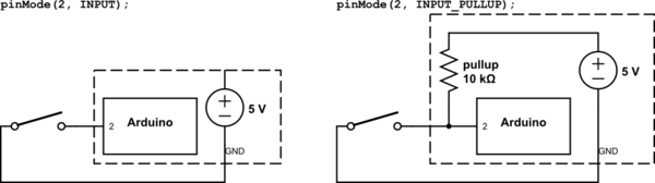
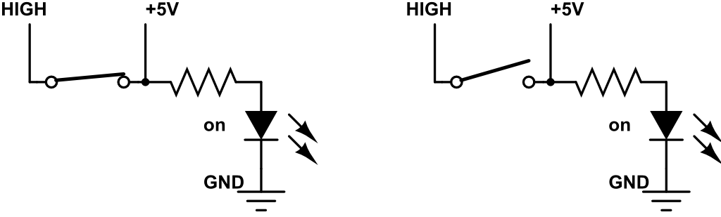
If we connect the switch in this way, and then order the Arduino to configure contact “2” as an INPUT contact, we get the circuit shown on the left (in the figure below). When the button is pressed, contact 2 will directly connect to ground / 0V, and when released, contact 2 will not be connected to anything. This state ( not connected to anything ) is called “floating” (a state with high impedance) and, unfortunately, it is not a very good state for our purposes. When we read data from a contact in the software ( using digitalRead (2) ), we get LOW if the contact is grounded, and an unpredictable result (LOW or HIGH) if the contact is in the floating state!
To fix this, we can configure the contact to be in INPUT_PULLUP mode, which connects to a resistor inside the processor and creates the circuit shown on the right. In this circuit, with the switch open, contact 2 has a path to + 5V, so when it is read, the result will always be HIGH. When the switch is closed, the contact will still have a path with high resistance to + 5V, as well as a path without resistance to ground / 0V, which “wins”, due to which we get LOW when reading the contact.
For software developers, the order may seem to be the reverse - when we press a button, we read false / LOW, and when it is released, true / HIGH.
You can do the opposite, but the processor has only built-in pull-up resistors and there are no drag-down resistors, so we will stick to this model.
The simplest program for Arduino, which reads the state of the switch and informs the PC about its state, looks something like the one shown below. You can click the download button in the Arduino IDE, and then open the Serial Monitor (in the Tools menu) to see the results.
void setup() { Serial.begin(9600); pinMode(2, INPUT_PULLUP); } void loop() { int state = digitalRead(pin); Serial.println( state == HIGH ? "Released" : "Pressed" ); delay(100);//artifically reduce the loop rate so the output is at a human readable rate... } Other switches almost without documentation ...
Three-pin LED switch
Fortunately, on the main switches of my panel there are marks of three contacts:

I'm not completely sure how it works, so we will switch the multimeter to continuity mode again and touch all contact pairs with the switch turned on and off ... however, this time the multimeter does not squeak when we touch the [GND] and [+] probes with On "switch! The only configuration in which the multimeter beeps ( detects a connection ) is when the switch is on, and the probes are on [+] and [lamp].
The LED inside the switch blocks the measurement of continuity, so from the checks made above, we can assume that the LED is connected directly to the [GND] contact, and not to the [+] and [lamp] contacts. Next we switch the multimeter to the diode test mode (symbol
 ) and check the pairs of contacts again, but this time the polarity is important ( red and black probe ). Now, if we connect the red probe with [lamp], and the black one with [GND], the LED will light up, and 2.25V will be displayed on the multimeter. This is the direct voltage of the diode, or the minimum voltage required to turn it on. Regardless of the position of the switch, 2.25V from [lamp] to [GND] causes the LED to light up. If we connect the red probe with [+], and the black one with [GND], the LED will light up only when the switch is on.
From these readings, we can assume that the insides of this switch look something like the diagram below:
- [+] and [lamp] are short-circuited when the switch is on / closed.
- A positive voltage from [lamp] to [GND] always lights the LED.
- A positive voltage from [+] to [GND] lights the LED only when the switch is on / closed.
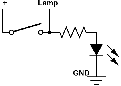
Honestly, the presence of a resistor here can only be guessed. The LED must be connected to the appropriate resistor to limit the current supplied to it, or it will burn. Mine is not burned and looks like it is working properly. On the seller’s website forum, I found a post that talks about an installed resistor that supports operation up to 12 V, and this saved me time to check / calculate a suitable resistor.
Connect the switch to the Arduino
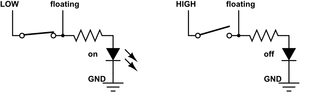
The easiest way to use the switch is with the Arduino, ignoring the [lamp] contact: connect [GND] to GND in Arduino and connect [+] with one of the numbered Arduino contacts, for example, 3.
If we configure pin 3 as INPUT_PULLUP ( as well as for the previous button ), we arrive at the result shown below. At the top left is the value that we will receive by executing “digitalRead (3)” in the Arduino code.
When the switch is on / closed, we read LOW and the LED lights up! To use this switch in this configuration, we can use the same Arduino code as in the button example.
Problems of this decision
After connecting to the Arduino, the complete chain looks like this:
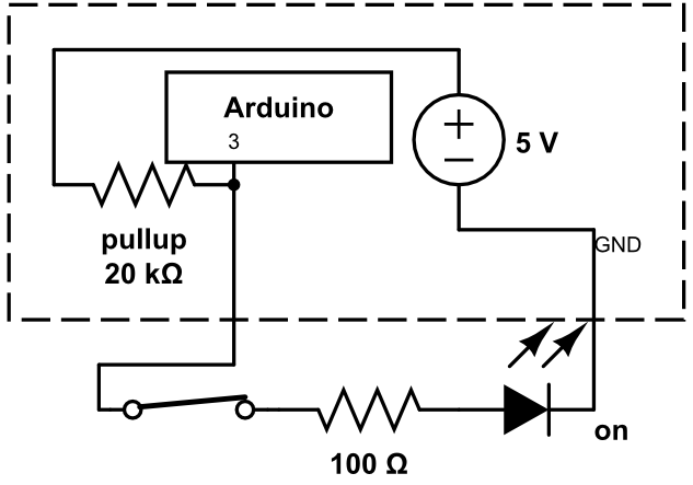
However, here we can see that when the switch is closed, in addition to a small current limiting resistor in front of the LED (I assume that its resistance is 100 Ohms), there is also a pull-up resistor of 20 kΩ, which further reduces the amount of current flowing through the LED. This means that while the circuit is working, the LED will not be very bright.
Another drawback of this scheme is that we do not have software control over the LED — it is turned on when the switch is on and turned off otherwise.
You can see what happens if we connect the [lamp] contact to either 0V or + 5V.
If [lamp] is connected to 0V, then the LED is always off ( regardless of the position of the switch ), and the recognition of the position of the Arduino still runs. This allows us to disable the LED programmatically if you wish!
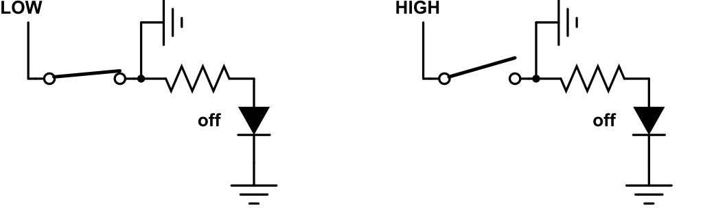
If [lamp] is connected to + 5V, then the LED is always on ( regardless of the position of the switch ), but the position recognition of the Arduino is broken - HIGH will always be read from the contact.
We connect this switch to the Arduino correctly
We can overcome the limitations described above ( low current / brightness of the LED and the lack of software control over the LED ) by writing more code! To resolve the conflict between the ability to control the LED and the position recognition broken because of it, we can divide two tasks in time, that is, temporarily turn off the LED when reading the sensor contact (3).
First, we connect the [lamp] contact to another general-purpose Arduino contact, for example, 4, so that the lamp can be controlled.
To create a program that will correctly read the switch position and control the LED (we will make it blink), we just need to turn off the LED before reading the switch state. The LED will turn off for only a fraction of a millisecond, so the flicker should not be noticeable:
int pinSwitch = 3; int pinLed = 4; void setup() { //connect to the PC Serial.begin(9600); //connect our switch's [+] connector to a digital sensor, and to +5V through a large resistor pinMode(pinSwitch, INPUT_PULLUP); //connect our switch's [lamp] connector to 0V or +5V directly pinMode(pinLed, OUTPUT); } void loop() { int lampOn = (millis()>>8)&1;//make a variable that alternates between 0 and 1 over time digitalWrite(pinLed, LOW);//connect our [lamp] to +0V so the read is clean int state = digitalRead(pinSwitch); if( lampOn ) digitalWrite(pinLed, HIGH);//connect our [lamp] to +5V Serial.println(state);//report the switch state to the PC } In Arduino Mega, pins 2-13 and 44-46 can use the analogWrite function, which actually does not create voltages from 0V to + 5V, but approximates it with a square wave. If desired, you can use it to control the brightness of the LED! This code will make the light pulsate, not just flicker:
void loop() { int lampState = (millis()>>1)&0xFF;//make a variable that alternates between 0 and 255 over time digitalWrite(pinLed, LOW);//connect our [lamp] to +0V so the read is clean int state = digitalRead(pinSwitch); if( lampState > 0 ) analogWrite(pinLed, lampState); } Build Tips
The post is already quite large, so I will not add another tutorial on soldering, you can google it!
However, I will give the most basic tips:
- When connecting wires with large metal contacts, first make sure that the soldering iron is heated and for some time heat and metal contact. The point of soldering is to form a permanent joint by creating an alloy, but if only one part of the joint is hot, then you can easily get a “cold joint” that looks like a joint but is not really connected.
- When connecting two wires, first put one piece of heat shrink tubing on one of them - after connecting the tube, you will not be able to put on the tube. This seems obvious, but I constantly forget about it and I have to use tape instead of a tube ... Pull the shrink tube away from the connection so that it does not heat up ahead of time. After checking the solder joint, slide the tube onto it and heat it.
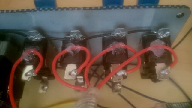
- Thin small connecting wires, which I mentioned at the beginning, are well suited for solderless connections (for example, when connected to an Arduino!), But rather fragile. After soldering, use a glue gun to fix them and eliminate all stresses from the connection itself. For example, the red wires in the picture below can be accidentally pulled while working, so after soldering I fixed them with a drop of hot glue:
Part 2. Turn the device into a game controller!
In order for the OS to recognize the device as a USB gaming controller, you need a fairly simple code, but, unfortunately, you also need to replace the firmware of the Arduino USB chip with another, which can be taken here: https://github.com/harlequin-tech/arduino-usb .
But after uploading this firmware to the Arduino, the device becomes a USB joystick and ceases to be an Arduino. Therefore, to reprogram it, you need to re-flash the original Arduino firmware. These iterations are quite painful - load the Arduino code, flash the joystick firmware, test, flash the arduino firmware, repeat ...
An example program for Arduino that can be used with this firmware is shown below — it configures three buttons as inputs, reads their values, copies the values into the data structure expected by this firmware, and then sends the data. Wash off, lather, repeat.
// define DEBUG if you want to inspect the output in the Serial Monitor // don't define DEBUG if you're ready to use the custom firmware #define DEBUG //Say we've got three buttons, connected to GND and pins 2/3/4 int pinButton1 = 2; int pinButton2 = 3; int pinButton3 = 4; void setup() { //configure our button's pins properly pinMode(pinButton1, INPUT_PULLUP); pinMode(pinButton2, INPUT_PULLUP); pinMode(pinButton3, INPUT_PULLUP); #if defined DEBUG Serial.begin(9600); #else Serial.begin(115200);//The data rate expected by the custom USB firmware delay(200); #endif } //The structure expected by the custom USB firmware #define NUM_BUTTONS 40 #define NUM_AXES 8 // 8 axes, X, Y, Z, etc typedef struct joyReport_t { int16_t axis[NUM_AXES]; uint8_t button[(NUM_BUTTONS+7)/8]; // 8 buttons per byte } joyReport_t; void sendJoyReport(struct joyReport_t *report) { #ifndef DEBUG Serial.write((uint8_t *)report, sizeof(joyReport_t));//send our data to the custom USB firmware #else // dump human readable output for debugging for (uint8_t ind=0; ind<NUM_AXES; ind++) { Serial.print("axis["); Serial.print(ind); Serial.print("]= "); Serial.print(report->axis[ind]); Serial.print(" "); } Serial.println(); for (uint8_t ind=0; ind<NUM_BUTTONS/8; ind++) { Serial.print("button["); Serial.print(ind); Serial.print("]= "); Serial.print(report->button[ind], HEX); Serial.print(" "); } Serial.println(); #endif } joyReport_t joyReport = {}; void loop() { //check if our buttons are pressed: bool button1 = LOW == digitalRead( pinButton1 ); bool button2 = LOW == digitalRead( pinButton2 ); bool button3 = LOW == digitalRead( pinButton3 ); //write the data into the structure joyReport.button[0] = (button1?0x01:0) | (button2?0x02:0) | (button3?0x03:0); //send it to the firmware sendJoyReport(joyReport) } Part 3. Integrating the device with your own game!
If you have control over the game with which the device should interact, then as an alternative, you can communicate with the controller directly - there is no need to make it visible to the OS as a joystick! At the beginning of the post, I mentioned Objects In Space; This approach was used by its developers. They created a simple communication ASCII protocol that allows the controller and the game to communicate with each other. It is enough to list the serial ports of the system ( they are also COM ports in Windows; by the way, look at how awful it looks in C ), find the port to which the device called “Arduino” is connected, and start reading / writing ASCII via this link.
On the Arduino side, we simply use the Serial.print functions that were used in the examples shown above.
At the beginning of this post, I also mentioned my library for this task: https://github.com/hodgman/ois_protocol .
It contains C ++ code that can be integrated into the game and used as a “server”, and Arduino code that can be executed in the controller to use as a “client”.
Customize Arduino
In example_hardware.h, I created classes to abstract individual buttons / switches; for example, “Switch” is a simple button from the first example., and “LedSwitch2Pin” is a switch with a controlled LED from the second example.
The sample code for my button bar is in example.ino .
As a small example, let's assume that we have a single button that needs to be sent to the game, and one game-controlled LED. The required Arduino code looks like this:
#include "ois_protocol.h" //instantiate the library OisState ois; //inputs are values that the game will send to the controller struct { OisNumericInput myLedInput{"Lamp", Number}; } inputs; //outputs are values the controller will send to the game struct { OisNumericOutput myButtonOutput{"Button", Boolean}; } outputs; //commands are named events that the controller will send to the game struct { OisCommand quitCommand{"Quit"}; } commands; int pinButton = 2; int pinLed = 3; void setup() { ois_setup_structs(ois, "My Controller", 1337, 42, commands, inputs, outputs); pinMode(pinButton, INPUT_PULLUP); pinMode(pinLed, OUTPUT); } void loop() { //read our button, send it to the game: bool buttonPressed = LOW == digitalRead(pin); ois_set(ois, outputs.myButtonOutput, buttonPressed); //read the LED value from the game, write it to the LED pin: analogWrite(pinLed, inputs.myLedInput.value); //example command / event: if( millis() > 60 * 1000 )//if 60 seconds has passed, tell the game to quit ois_execute(ois, commands.quitCommand); //run the library code (communicates with the game) ois_loop(ois); } Customize the game
The game code is written in the style of "single header". To import the library, we include into the game oisdevice.h .
In a single CPP file, before executing the #include header, we will write #define OIS_DEVICE_IMPL and #define OIS_SERIALPORT_IMPL - this will add the source code of the classes to the CPP file. If you have your own statements, logging, strings or vectors, then there are several other OIS_ * macros that can be defined before importing a header to take advantage of the engine.
You can use the following code to list the COM ports and create a connection with a specific device:
OIS_PORT_LIST portList; OIS_STRING_BUILDER sb; SerialPort::EnumerateSerialPorts(portList, sb, -1); for( auto it = portList.begin(); it != portList.end(); ++it ) { std::string label = it->name + '(' + it->path + ')'; if( /*device selection choice*/ ) { int gameVersion = 1; OisDevice* device = new OisDevice(it->id, it->path, it->name, gameVersion, "Game Title"); ... } } After receiving an OisDevice instance, you should regularly call its Poll member function (for example, in each frame), you can get the current state of the controller's output using DeviceOutputs (), use device events using PopEvents (), and send values to the device using SetInput ().
An example of an application doing all this can be found here: example_ois2vjoy / main.cpp .
Part 4. What if I want parts 2 and 3 at the same time?
In order for the controller to work in other games (part 2), you need to install your own firmware and one Arduino program, but in order for the controller to be fully programmed by the game, we used the standard Arduino firmware and another Arduino program. But what if we want both possibilities at the same time?
An example of the application to which I gave the link above ( ois2vjoy ) solves this problem.
This application communicates with the OIS device (program from part 3), and then on the PC converts this data into ordinary controller / joystick data, which is then transmitted to the virtual controller / joystick device. This means that you can allow your controller to constantly use the OIS library (no other firmware is required), and if we want to use it as a normal controller / joystick, then just run the ois2vjoy application on the PC that performs the conversion.
Part 5. Completion
I hope someone this article seemed useful or interesting. Thank you for reading to the end!
If you are curious, then I invite you to participate in the development of the ois_protocol library! I think it would be great to develop a single protocol to support all sorts of self-made controllers in games and encourage the games to directly support self-made controllers!
Source: https://habr.com/ru/post/442816/
All Articles