Moscow Metro application for Windows Store
I wanted to make the application of the Moscow metro as soon as Artemy Lebedev and his studio drew a metro map in its current form.
1. Baseline
Now the official metro map can be downloaded to PDF from the official website of the Moscow Metro . At the time of the creation of the application (mid-2013), the scheme was available in the form of an .ai file (Adobe Illustrator) on the website of the Lebedev Studio. In any case, the next step is to prepare the data in Illustrator.
2. Data preparation
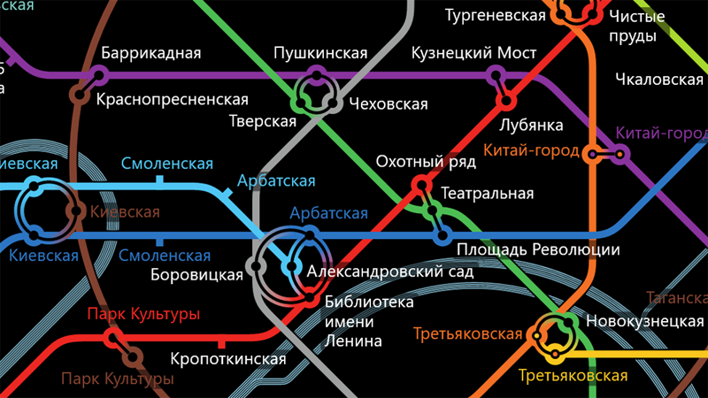
We open PDF in Illustrator, we include the preview mode and
')
horror-horror
(clickable)
(clickable)
After a long and painstaking work (here many years of experience in the Moscow advertising newspaper came in handy, first in the design and layout department, then in the IT department)
got the following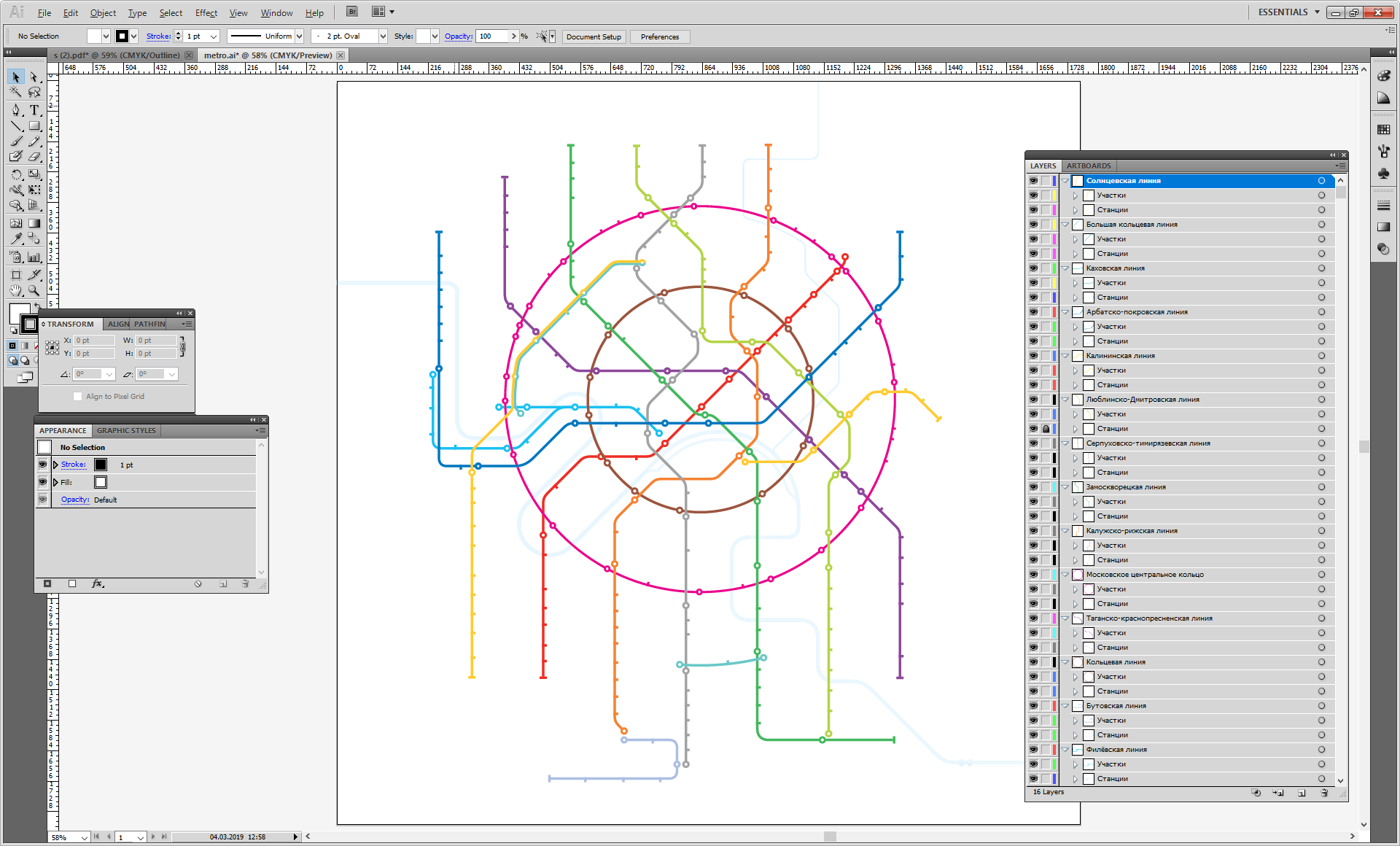
(clickable)
(clickable)
What was done:
- removed numerous garbage, labels, etc.
- each metro line was divided into sections between stations. The lines were broken under the station drawings so that when drawing the constructed routes there were no visible joints and gaps.
like this: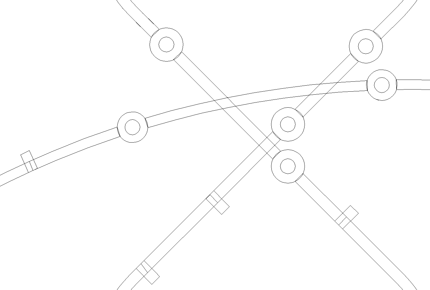
- all the “pieces” of lines and all stations belonging to each line are grouped into layers, in the order of their sequence.
like this: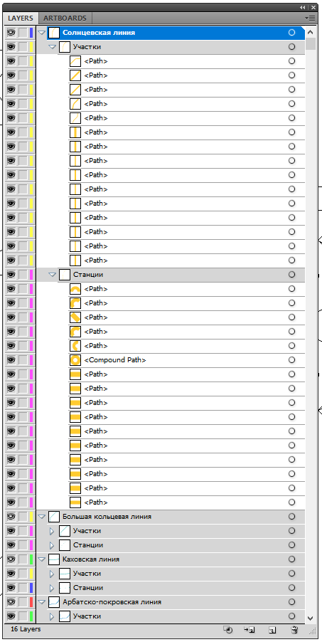
3. Convert graphics to XAML
To convert graphics to XAML, Microsoft Expression Design is used. Everything is simple - open the ai-file, export to XAML.
Microsoft Expression Design: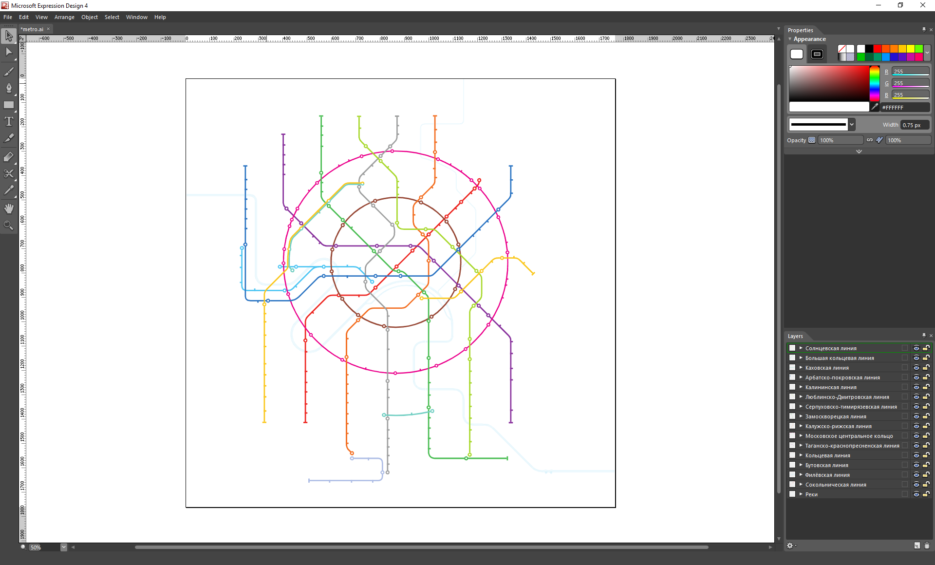
(clickable)
(clickable)
4. Starting programming (finally)
Currently, Visual Studio 2015 and the MVVM framework MVVM-light are used for development. Unfortunately, the XAML file obtained in the previous step cannot be used directly in the application, except for the static layer with rivers and “aeroexpress” routes.
Therefore, a little more manual work - and in the application resources we create the final XML file used for rendering the metro map. When it is loaded, objects of metro lines and metro stations are formed, links between stations are formed within the same line, transitions between lines, and ring lines “close”. By the way, the transitions between the lines are formed by software. Between the two stations - lines are drawn with a gradient of the fill, between the three stations - arcs of a circle are constructed that are built on three points - the centers of the stations that make up the transition.
An example of a view-layer responsible for drawing transition arcs between three stations (for the sake of brevity, the resources responsible for animation, etc. have been removed):
<ItemsControl x:Name="ArcCrossings" ItemsSource="{Binding CrossingArcTypeList}" Visibility="Visible" Height="1760" Width="1765"> <ItemsControl.ItemTemplate> <DataTemplate> <Grid x:Name="grid" Opacity="{Binding Dimmed, Converter={StaticResource BooleanToOpacityConverter}}"> <Path StrokeThickness="7.7" Stroke="{Binding CrossBrush}"> <Path.Data> <PathGeometry> <PathGeometry.Figures> <PathFigureCollection> <PathFigure StartPoint="{Binding GradientLineStartPoint}"> <PathFigure.Segments> <PathSegmentCollection> <ArcSegment Point="{Binding GradientLineEndPoint}" Size="{Binding ArcSize}" SweepDirection="Clockwise"/> </PathSegmentCollection> </PathFigure.Segments> </PathFigure> </PathFigureCollection> </PathGeometry.Figures> </PathGeometry> </Path.Data> </Path> <Path StrokeThickness="2.4" Stroke="{Binding SettingsVM.BackMainBrush, Source={StaticResource Locator}}"> <Path.Data> <PathGeometry> <PathGeometry.Figures> <PathFigureCollection> <PathFigure StartPoint="{Binding BlackLineStartPoint}"> <PathFigure.Segments> <PathSegmentCollection> <ArcSegment Point="{Binding BlackLineEndPoint}" Size="{Binding ArcSize}" SweepDirection="Clockwise"/> </PathSegmentCollection> </PathFigure.Segments> </PathFigure> </PathFigureCollection> </PathGeometry.Figures> </PathGeometry> </Path.Data> </Path> </Grid> </DataTemplate> </ItemsControl.ItemTemplate> <ItemsControl.ItemsPanel> <ItemsPanelTemplate> <Canvas/> </ItemsPanelTemplate> </ItemsControl.ItemsPanel> </ItemsControl> To search for routes, the wave algorithm is used with small variations. For example, in case there is an optimal route containing two or more junctions, additional routes are built in which it is prohibited to use "intermediate" metro lines. As a result, sometimes extremely paradoxical and unexpected travel options are obtained (see screenshots below).
The following approach was used to search for the necessary car for convenient transfer to another metro line: each line has a “forward” and “reverse” direction. Accordingly, it is important to us from which side we drove to the transition station, and sometimes it is still important to us in which direction we will go along the line to which we are going.
A fragment of an XML file describing the China-Gorod station of the Tagansko-Krasnopresnenskaya line and its characteristic transition to the Kaluga-Riga line:
<Station name="-" lat="55.755361" lon="37.632361" Width="16.8277" Height="16.8282" Canvas.Left="1011.71" Canvas.Top="741.034" Data="F1 M 1017.45,746.771C 1015.97,748.25 1015.97,750.646 1017.45,752.125C 1018.93,753.604 1021.33,753.603 1022.8,752.125C 1024.29,750.646 1024.28,748.25 1022.81,746.77C 1021.33,745.292 1018.93,745.292 1017.45,746.771 ZM 1014.2,755.425C 1010.91,752.15 1010.88,746.824 1014.15,743.524C 1017.43,740.225 1022.75,740.2 1026.05,743.473C 1029.35,746.744 1029.38,752.071 1026.1,755.371C 1022.83,758.672 1017.51,758.695 1014.2,755.425 Z " TextLabel.Left="2" TextLabel.Top="-15" ShowPad="1" IsCrossPlatform="true" CrossPlatformColor="FFF37025"> <transfers> <forward> <transfer LineID="400" station="-"> <forward vagons="11111"/> <backward vagons="00100"/> </transfer> </forward> <backward> <transfer LineID="400" station="-"> <forward vagons="00100"/> <backward vagons="11111"/> </transfer> </backward> </transfers> </Station> 5. Several screenshots of built routes (clickable)
Unexpected route from Kiev-Koltsevaya to Kursk-Koltsevaya: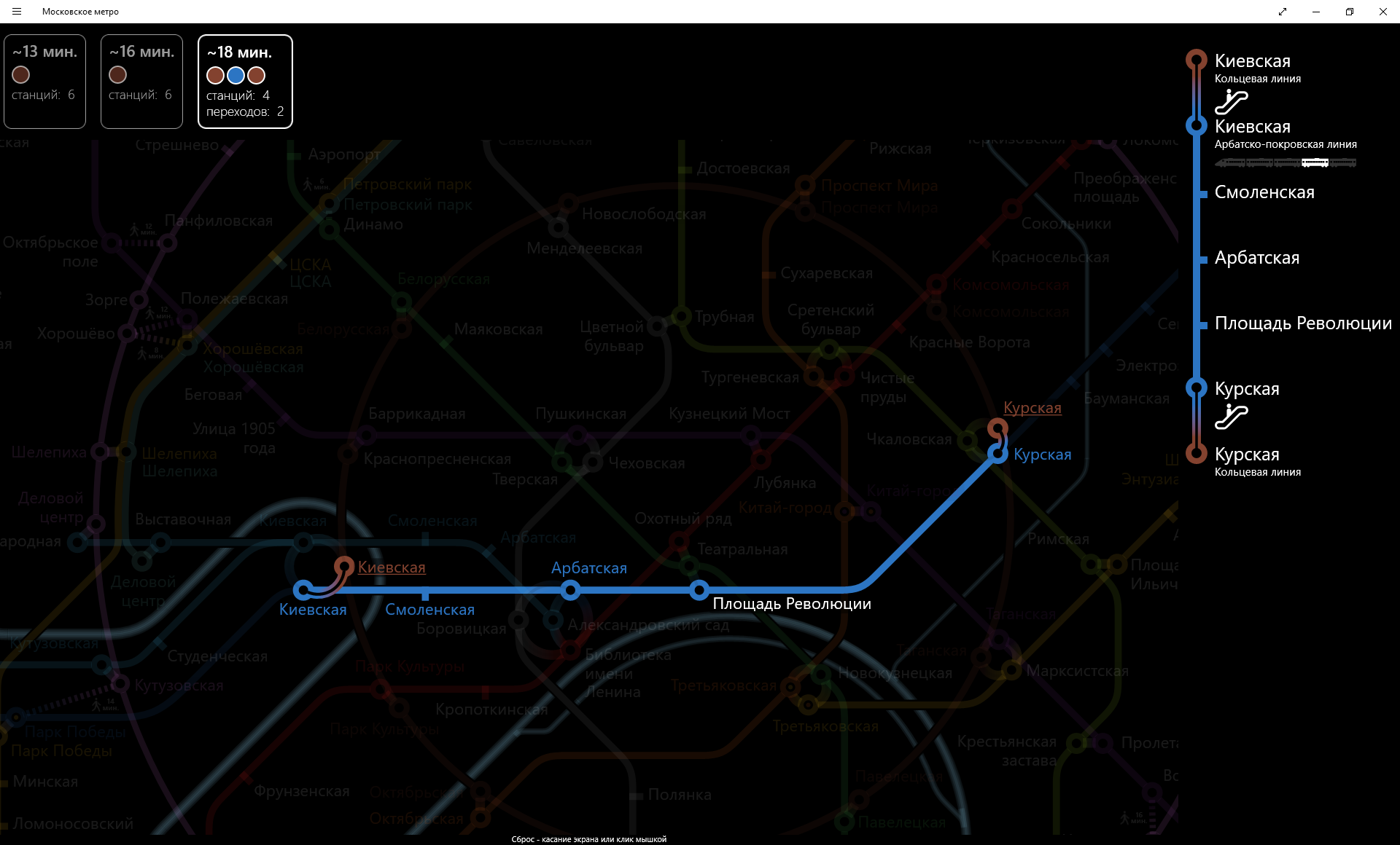
An even more unexpected route from the Alexander Garden to Borovitskaya:
From Okhotny Ryad to Revolution Square: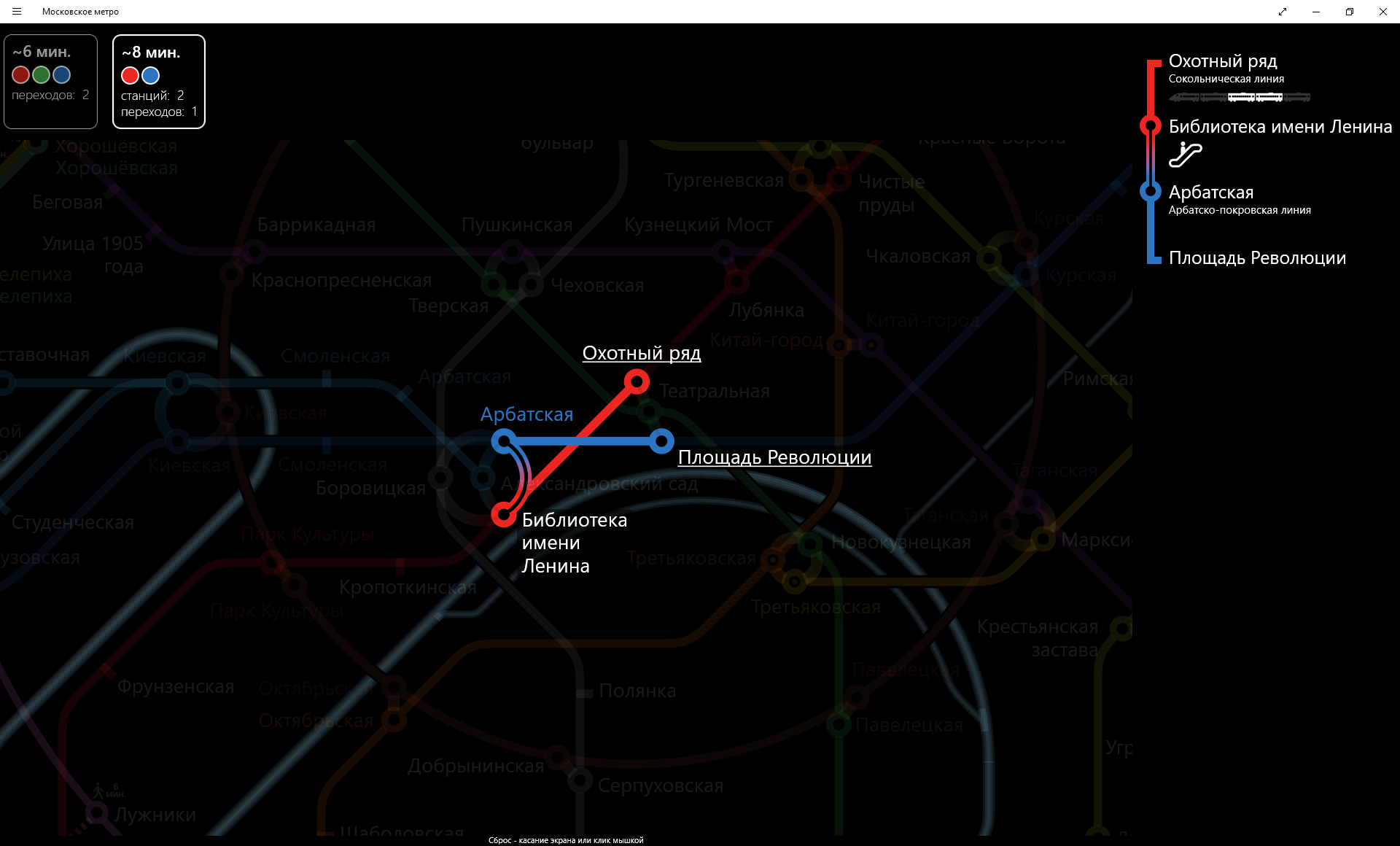
Quite ordinary from Shabolovskaya to Tula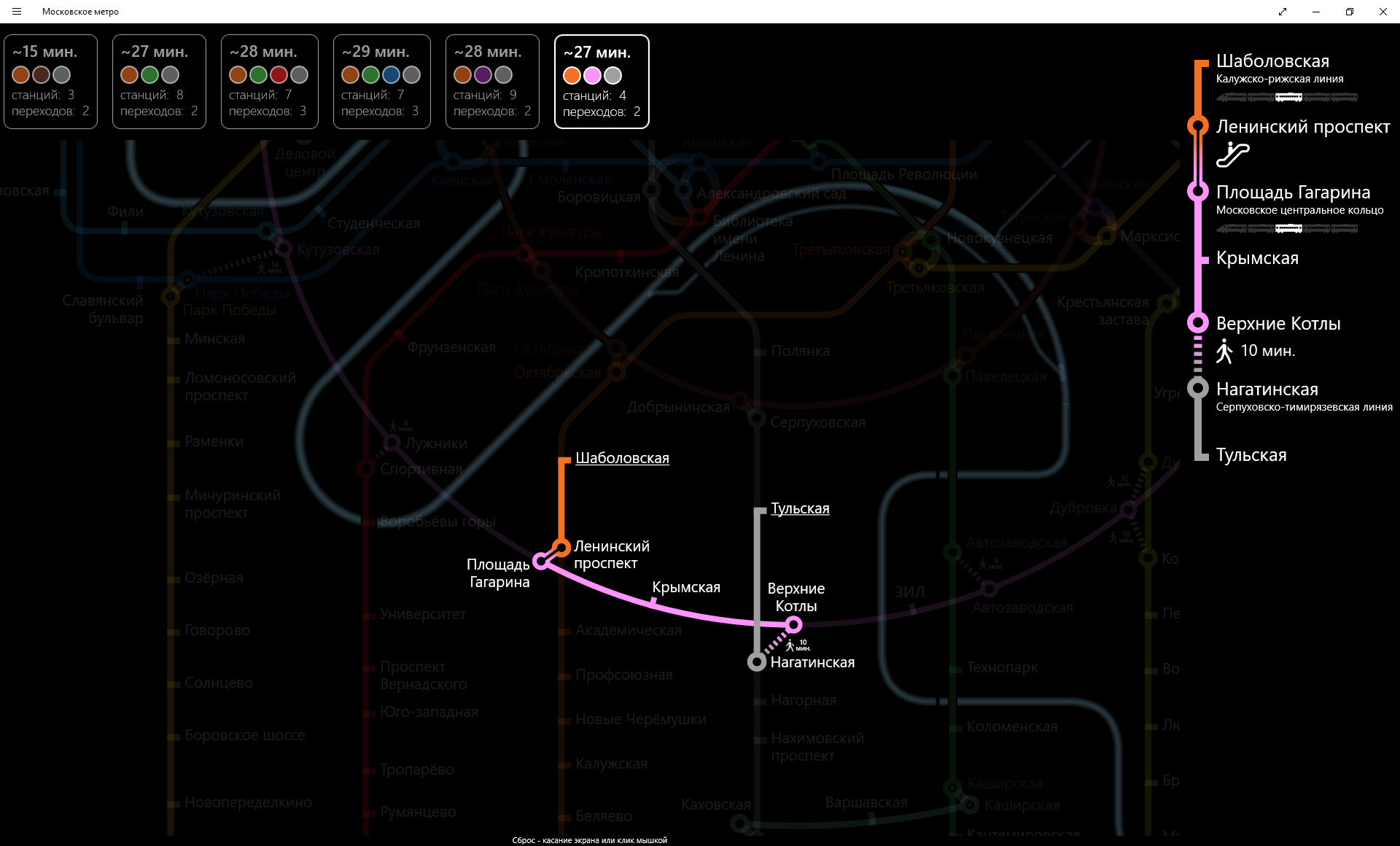
Another route from Shabolovskaya to Tula in the light mode of the scheme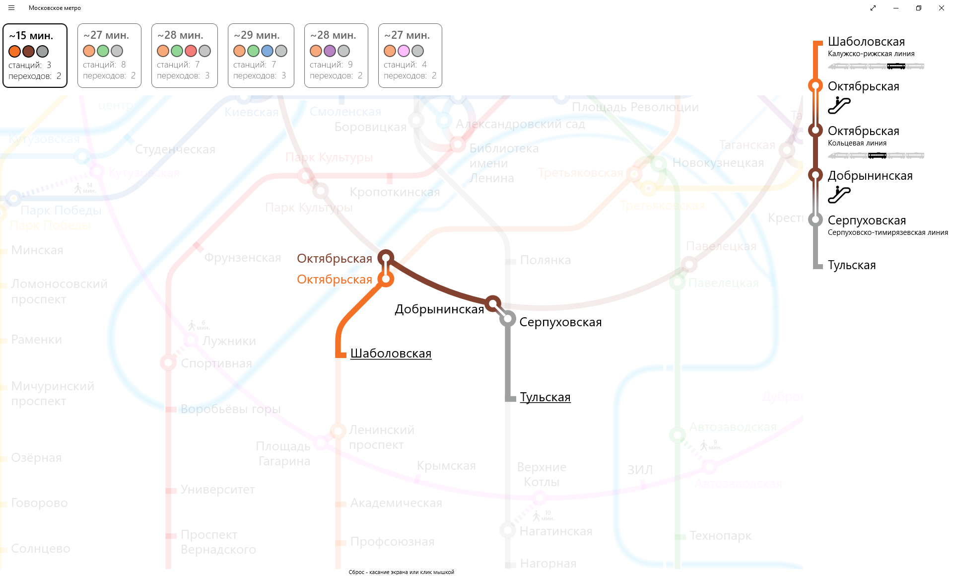
General view of the scheme (light mode)
General view of the scheme (dark mode)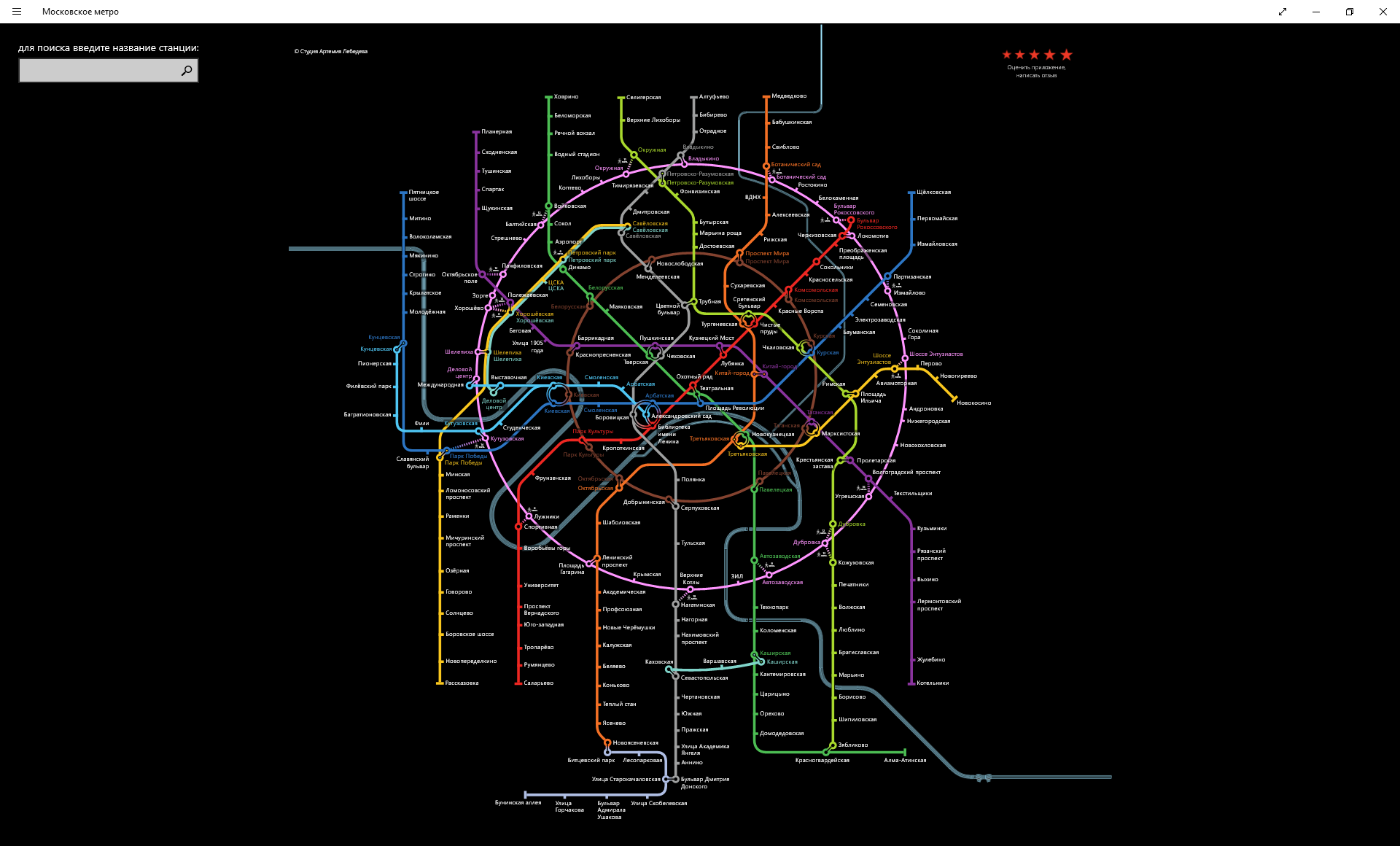
Search stations (all starting with 'P')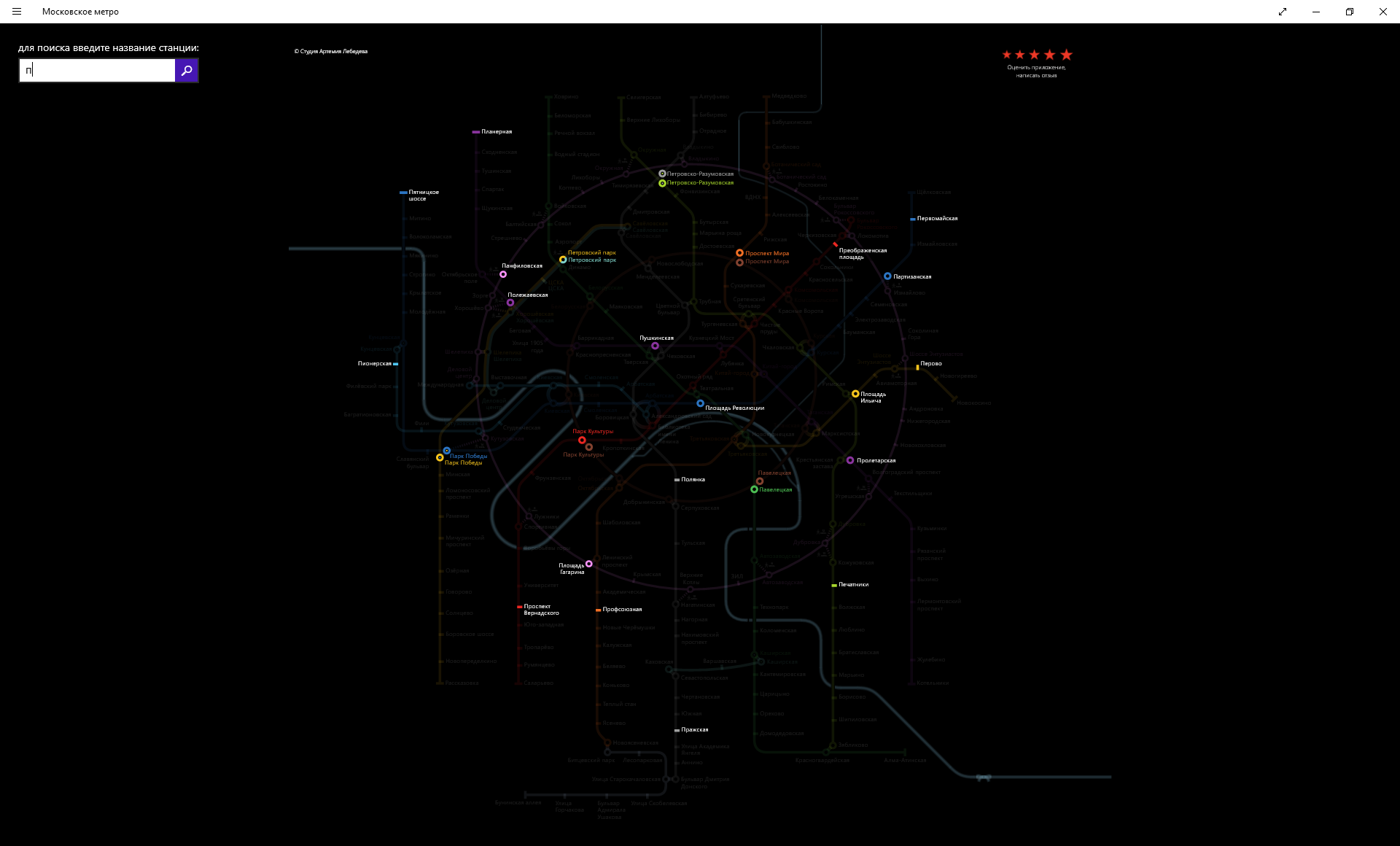
6. Plans
At the time of the development of the application (remember - this is the beginning-middle of 2013), it was about Windows 8 - 8.1. Actually, the application is still "non-UWP". Accordingly, the application still has the Windows 8.1 “birthmarks”, in particular, the ambiguous location of the application settings. What can we say, in Windows 10, the “charm” of the settings “a la Windows 8.1” looks slightly alien. Over time, this will probably be changed.
how is it now: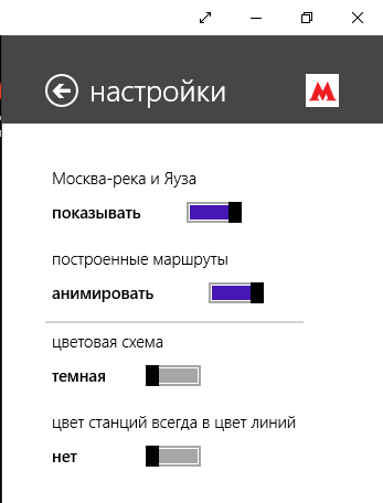
In the last update I had to “cut out” information about the exits to the city (i.e., now there is no clue which car to sit in so that it is convenient to go to the city). This is in the near future.
Source: https://habr.com/ru/post/442698/
All Articles