Universal machine for carrying out tests do yourself part 1
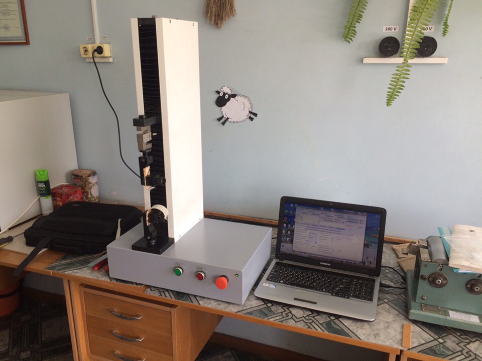
Continuing the themes ( first , second ) about testing machines, I want to assemble a budget version of a cantilever type machine, for a small load (20 kg), for testing various materials ...
After writing the previous two articles on this topic, I was asked questions related to modernization and development. This prompted me to write an article. It will consist of two parts - in this I will talk about the mechanical part, and the second will be devoted to electronics, software and data processing.
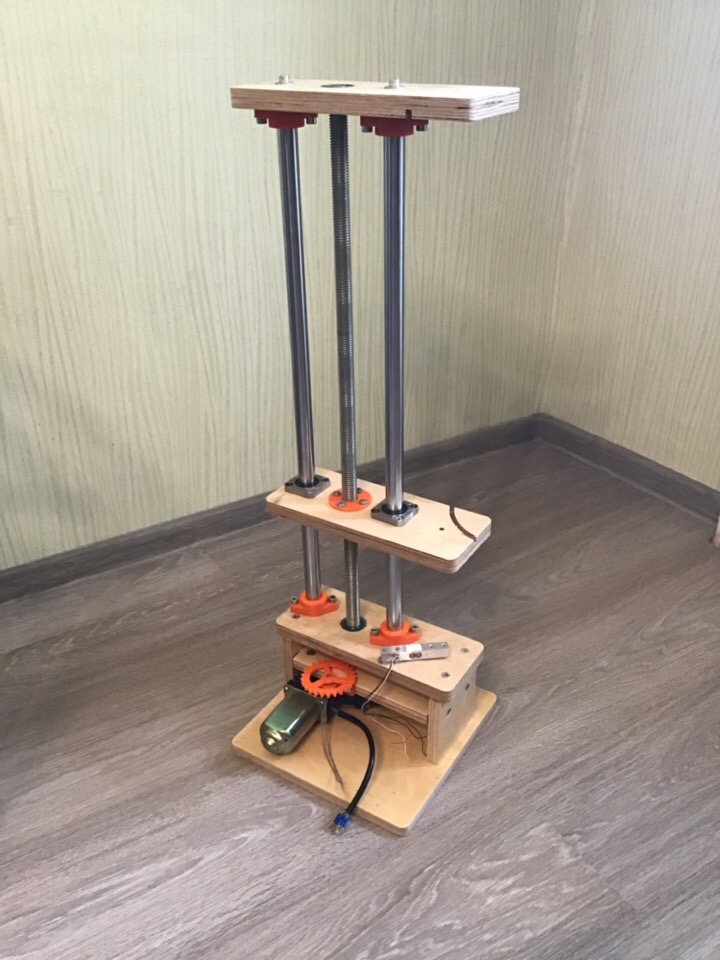
The kinematic scheme decided to take a console type, since it is easier to implement and smaller in size (compared to a two-column machine) with the same set of characteristics, but structurally it is slightly weaker.
')
I laid down the following basic characteristics for my car: maximum load capacity of 20 kg or 200 N, and maximum working stroke of 600 mm.
Starting the design, I decided on the basic materials for the manufacture of machine parts. Cylindrical guides 20 diameter and carriage to them decided to buy, without inventing a bicycle. He took a construction stud and a nut with an M20 thread in 2.5 mm pitch as a moving mechanism. The connecting plates of the load frame, including the base of the machine, were decided to be made of 20 mm thick plywood.
A small digression for those who began to laugh: this project is planned to be quite budgetary, and is needed for working out the scheme of using the selected electronics and developing a program for managing and processing data on a personal computer.
The use of a trapezoidal screw or screw screw, and also in place of plywood - duralumin or steel, will significantly increase the cost of the machine, but I still do it not for sale, but to repeat this project, by those who need such a load-bearing unit. Who, what kinematic scheme will be used and from which components of each person’s case.
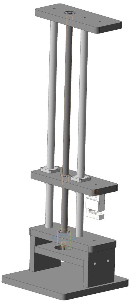
I threw in the project in Compass, only the main parts, with the manufacturing technology of which was immediately determined. In view of the fact that I have a CNC milling machine, almost all the components of the machine made of plywood I decided to process on it.
Laid out all the flat parts in a two-dimensional projection, saved them in vector format (* .dxf). Through the postprocessor in the CAM program, he transferred the drawings to G-code. The machine cut out all the details for one installation of the workpiece, since the dimensions of its working field allow. After processing the corners with sandpaper, all the mating parts fit very well together.
The guides and studs were machined on a lathe. As we did not try to make a pin without a beat, it still remained a curve.
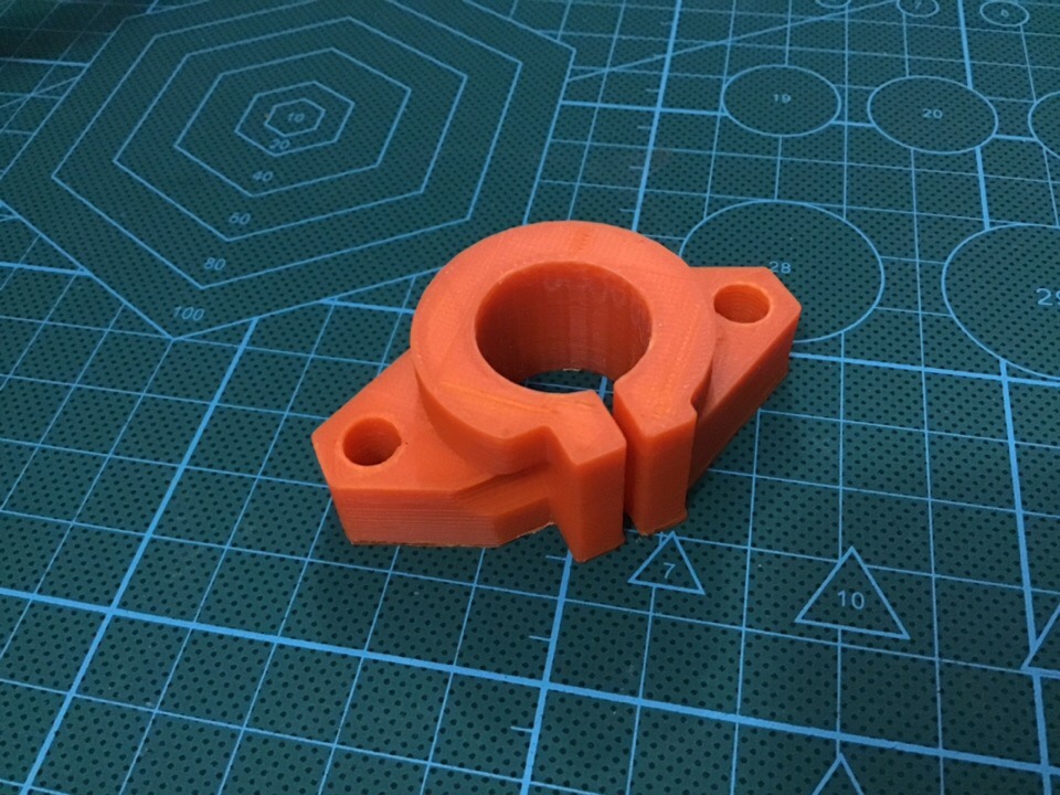
After the preliminary assembly of the power frame, it became clear that it was necessary to strengthen the mounting of the cylindrical guides to the upper and lower plates. This required additional support, but buying them is expensive, but to make them out of plastic on a 3D printer is the most.
I picked up the supports for the diameter of my guides from the catalog, drew them in 3D according to the available sizes, all in the same Compass.
A friend gave for temporary use a 3D printer, for a couple of days I managed to print all the supports and a few more details. The printed supports stood up very tightly, and this gave the whole structure a good rigidity.
On the machined ends of the studs, on landing put on the ball radial bearings. At the bottom of the bearings between the bottom plate pulled the nut. Properly, you must use support bearings or tapered.

As the power plant I decided to use a gear motor from the window regulators of the VAZ 2110, it creates a good torque. He suggested that it would be enough to roll the pin, loaded with twenty kilograms.
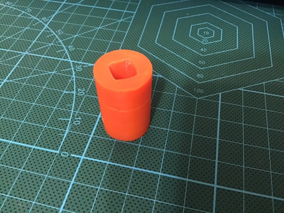
The output shaft of the motor - gearbox square section 7x7 mm., To connect it with the tail of the stud had to print the clutch.
With regard to the operation of the engine with respect to the testing machine, in order to carry out a correct test, the speed of the load should remain virtually unchanged. In modern propulsion systems, this is implemented in electronic control drives. In my case, however, so that during the load the speed of the moving plate does not decrease, the engine must have such power that it does not notice the load increasing on it, or implement it programmatically, raising the power. But in this case, you need to have feedback to control the speed.
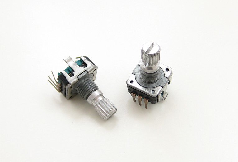
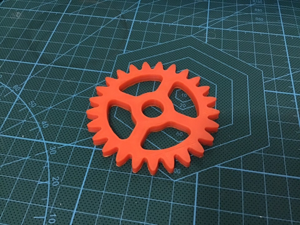
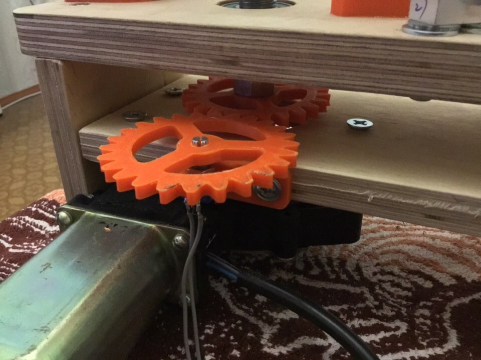
To measure the moving distance of the movable plate, I decided to set the encoder to 24 pulses per revolution, this will allow measuring the distance with an accuracy of 0.1 mm, this is more than enough, given that there is a gap in the articulation pin / nut. I hope that the encoder will help me in measuring the real speed of movement. The sensor decided to move to the side, having printed two gears with a one-to-one gear ratio, as well as a bracket for fastening it to the end of the supporting plate of the motor - gearbox. After printing, the gears turned out to be a little figure eight, but it's not scary, the main thing is that there is a link between them.
The car turned out with two work areas, the lower and upper. The force sensor for 20 kg, as well as the assembled machine, of the cantilever type, I installed it in the lower part so that the wires do not interfere in the case of fastening on the mobile or top plate.
The first part of this came to an end, pleasant reading, friends!
PS: Please indicate any errors in a personal message.
After writing the previous two articles on this topic, I was asked questions related to modernization and development. This prompted me to write an article. It will consist of two parts - in this I will talk about the mechanical part, and the second will be devoted to electronics, software and data processing.
The kinematic scheme decided to take a console type, since it is easier to implement and smaller in size (compared to a two-column machine) with the same set of characteristics, but structurally it is slightly weaker.
')
I laid down the following basic characteristics for my car: maximum load capacity of 20 kg or 200 N, and maximum working stroke of 600 mm.
Starting the design, I decided on the basic materials for the manufacture of machine parts. Cylindrical guides 20 diameter and carriage to them decided to buy, without inventing a bicycle. He took a construction stud and a nut with an M20 thread in 2.5 mm pitch as a moving mechanism. The connecting plates of the load frame, including the base of the machine, were decided to be made of 20 mm thick plywood.
A small digression for those who began to laugh: this project is planned to be quite budgetary, and is needed for working out the scheme of using the selected electronics and developing a program for managing and processing data on a personal computer.
The use of a trapezoidal screw or screw screw, and also in place of plywood - duralumin or steel, will significantly increase the cost of the machine, but I still do it not for sale, but to repeat this project, by those who need such a load-bearing unit. Who, what kinematic scheme will be used and from which components of each person’s case.
I threw in the project in Compass, only the main parts, with the manufacturing technology of which was immediately determined. In view of the fact that I have a CNC milling machine, almost all the components of the machine made of plywood I decided to process on it.
Laid out all the flat parts in a two-dimensional projection, saved them in vector format (* .dxf). Through the postprocessor in the CAM program, he transferred the drawings to G-code. The machine cut out all the details for one installation of the workpiece, since the dimensions of its working field allow. After processing the corners with sandpaper, all the mating parts fit very well together.
The guides and studs were machined on a lathe. As we did not try to make a pin without a beat, it still remained a curve.
After the preliminary assembly of the power frame, it became clear that it was necessary to strengthen the mounting of the cylindrical guides to the upper and lower plates. This required additional support, but buying them is expensive, but to make them out of plastic on a 3D printer is the most.
I picked up the supports for the diameter of my guides from the catalog, drew them in 3D according to the available sizes, all in the same Compass.
A friend gave for temporary use a 3D printer, for a couple of days I managed to print all the supports and a few more details. The printed supports stood up very tightly, and this gave the whole structure a good rigidity.
On the machined ends of the studs, on landing put on the ball radial bearings. At the bottom of the bearings between the bottom plate pulled the nut. Properly, you must use support bearings or tapered.
As the power plant I decided to use a gear motor from the window regulators of the VAZ 2110, it creates a good torque. He suggested that it would be enough to roll the pin, loaded with twenty kilograms.
The output shaft of the motor - gearbox square section 7x7 mm., To connect it with the tail of the stud had to print the clutch.
With regard to the operation of the engine with respect to the testing machine, in order to carry out a correct test, the speed of the load should remain virtually unchanged. In modern propulsion systems, this is implemented in electronic control drives. In my case, however, so that during the load the speed of the moving plate does not decrease, the engine must have such power that it does not notice the load increasing on it, or implement it programmatically, raising the power. But in this case, you need to have feedback to control the speed.
To measure the moving distance of the movable plate, I decided to set the encoder to 24 pulses per revolution, this will allow measuring the distance with an accuracy of 0.1 mm, this is more than enough, given that there is a gap in the articulation pin / nut. I hope that the encoder will help me in measuring the real speed of movement. The sensor decided to move to the side, having printed two gears with a one-to-one gear ratio, as well as a bracket for fastening it to the end of the supporting plate of the motor - gearbox. After printing, the gears turned out to be a little figure eight, but it's not scary, the main thing is that there is a link between them.
The car turned out with two work areas, the lower and upper. The force sensor for 20 kg, as well as the assembled machine, of the cantilever type, I installed it in the lower part so that the wires do not interfere in the case of fastening on the mobile or top plate.
The first part of this came to an end, pleasant reading, friends!
PS: Please indicate any errors in a personal message.
Source: https://habr.com/ru/post/442408/
All Articles