What is slightly wrong Oleg Artamonov

After reading a note about a hypothetical "impartial tomorrow," the young, growing, inquisitive, strengthening engineering mind must be inflamed with righteous anger and, pressing to the chest [of course, de-energized and cooled] soldering iron with one hand and putting the second on the collective bible formed by a pile of worn semiconductor reference books to products, sincerely, hotly, tearfully, solemnly swear everything, always, everywhere, to do only and only correctly! But how to correct? The following note about the "fundamentals of electrical safety" , designed to be for such young minds, if not guiding, as well as explaining, itself requires clarification, clarification, and even ... some amendments.
This article does not claim to be a guiding one, but is designed very carefully, a little bit (so that the revolutionary fire of the agitated mind is not disappointed in the contradictions with the dry, harsh reality) to open the door to the pantry of traditional professional defaults.
Volt Volt strife
Electric current can be of different quality; distinguish, at least: direct, alternating and pulse currents. Quantitatively, a current is characterized, at a minimum, by a force measured in amperes and a voltage measured in volts. When meeting an expression like “several volts”, it is always necessary to stipulate (negotiate) which volts exactly? That is, exactly what meaning (peak, acting, some other) is meant, since it is not always clearly or clearly readable from the context. Some current traditions in this area are listed below.
VAC, Vac, Va.c. - this means the effective value (for a pure sinusoidal signal is equivalent to the root-mean-square value) [voltage] of the alternating current of the industrial frequency (50 or 60 Hz).
')
VDC, Vdc, Vd.c. - so designate (as a rule, the average, without emissions) value [voltage] of a constant (rectified) current.
V ~, Vrms - this is the meaning of the rms value of [voltage] of alternating current of any frequency.
Vpeak, Vp, Vp-o - this means the amplitude (peak) value [voltage] of any kind (DC, AC, pulse) taken (value) from any average value (for cases of alternating current, as a rule, zero).
Vp-p - this is the meaning of the peak (to-peak) amplitude [voltage] (also, as a rule, taken from some average value).
V =, Vavg, Vo - this is the meaning (as a rule, the averaged, smoothed) value [of the] voltage of the direct (rectified) current.
Such a “context-independent” expression of values allows the values (characteristics) to speak immediately on the spot for themselves, without taking away the focus of attention of the reader. Due to this, typical expressions (characteristics, conditions), such as, for example, U = 230 Vac, Umin = 20 Vrms @ 300 kHz, Umax = 46 Vp, firstly, look compact (“right on the spot”) and, -second, reveal their own essence wider ("for themselves").
Unfortunately, the Russian-language approach does not provide such brevity and clarity, even the basic concepts of “alternating current” and “direct current” are added to the same abbreviation “p. ", and the expressions like" 71 V peak value "and" 63 kV rms values "that are present in GOST IEC 60950-1 are not comparable with the corresponding" 71 V peak "and" 63 "lightness and sharpness of perception. kV rms "in the English original. Therefore, further, in order to be less confused, it is the “English version” that is used for semanting the values of units of measurement.
IEC 60950-1
The publication of IEC 60950-1 refers to the [historically inertly still] so-called “horizontal” safety standards (safety), which (by definition) do not establish requirements for a particular type (type) of equipment. Such requirements, as a rule, are set either by the vertical standard (particular requirements) or the specifications (specifications) for the type (type) of equipment, if there is no state (or international) standard for this type (type) of equipment.
For example, IEEE 802.3 establishes the requirement that the Ethernet port requires basic insulation (level insulation) at a level of 1.5 kV AC (withstand voltage 1500 VAC) according to IEC 60950-1, defining in this way the required ("vertical" input) operational the characteristic that the reference (“called”) horizontal standard “dereferences” (reveals, complements, specifies) with sufficient (“horizontal” output) structural characteristics (requirements), such as air gap and creepage distance.
IEC 60950-1 is based on the “single failure” model, which means that any failure (in any part of the product) makes the entire product inoperative. In other words, everything is good in the product *, so far everything is good in everything (there is not a single refusal), and in the product (more attentively) everything (!) Is not good ** if there is anything in it at least not good. Yes, IEC 60950-1 does not consider (and even in no way implies) fault-tolerant systems.
Under the footnotes above, the following comment can be made: the standard in question itself is intended to ensure the safety of a person who is dealing only and only with the product in the “all good” state (*); safety when working with a product that is already in the reverse state (**), or still in a state of direct transition (degradation during failure) to it, is not included in the scope (regulation) of the standard.
With regard to the safety of electrical insulation, along with the definition of design characteristics according to comprehensively established external requirements (Appendix G), IEC 60950-1 allows (in the case of incomplete external requirements) the determination of such characteristics in an analytical way based on the calculation (or measurement on a prototype) of the corresponding peak workers stresses. However, it is worth remembering that such an analysis also comes from the assumption that “everything is fine”.
For example, the fact that a PC to which, say, a USB to RS485 converter is connected, has a power supply unit (node) that is connected to primary circuits of the [power supply network with dangerous alternating current voltage] does not even mark (fully possible ) the need for galvanic isolation between these interfaces, since in the “all is well” state the corresponding secondary circuits are considered either in fact or equivalently attracted to the “earth” (protective ground). Such isolation here can only be an external requirement.
With regards to the analytical method mentioned, it is also worth adding that the possible result (among other things) is also influenced by the characteristics of the specific design (circuit diagram, tracing figure) of the product (hence the presence of at least a prototype on which measurements can be made). For a comprehensive acquaintance with the whole process, it is better to refer directly to the text of the standard itself. So, what to read?
The English original IEC 60950-1 (and its replicas in the same language, such as UL 60950-1, EN 60950-1) is already outlined in a somewhat frivolous manner (not always and not always technically accurate, uniquely interpreted, exhaustively defined) and unpleasantly surprising number of cross references within oneself. In general, this is far from easy reading and far from cheap (the original is sold to IEC for about a thousand euros per document). On the other hand, the original is the original.
The Russian-language translation of GOST IEC 60950-1 was developed in an attempt to obtain an “identical translation” (IDT) of the original, which it copes with on average, but does not convey the fullness of the source text due to the presence of various degrees of roughness in the translation. Normatively subordinate to the original and, at the same time, sensitively inferior to the original in quality. In any case, it is recommended to familiarize with the purpose of primary immersion in the topic.
In comparison with the Russian-language translation, laid out in the "ponomatic" style, the original is much more convenient for visual perception, not to mention the "sutie" surfing the text itself. (It just so happens that today it is English that is at the mercy of science and technology, therefore every engineer is obliged to know it at the level of reading technical literature.) The original is simply strongly recommended for everyone who has professional (or other engineering) interest in the topic in question.

(For a “quote” from GOST, see here. )
“Nominal voltage” and “isolation level”
When developing an electrical appliance, the designer, as a rule, deals with two categories of electrical influences that (influences) will (can be) characteristic of such an appliance. These two categories are hereinafter referred to as “nominal voltage” and “isolation level”, respectively, and are defined as follows.
"Native voltage" - implies that the corresponding signal is present on the powered (turned on, normally working) device for, as a rule, an unlimited time. (In the case of a mains power signal, the instrument is powered from the same signal.)
“Insulation level” is characterized by test voltage (as a rule, multiple of “nominal voltage”) and exposure time [test voltage to the device] (usually tens of seconds, the typical value is one minute), as well as the test voltage applied to the device only in de-energized (!) condition.
For combinations of various electrical circuits of the device, only “nominal voltage”, only “isolation level”, “nominal voltage” plus “isolation level”, neither can be set [relevant requirements]. The values themselves [established by the relevant requirements] "nominal stresses" and "isolation levels" can differ both quantitatively and qualitatively.
For example, for a [hypothetical] “notebook” power supply unit that has five electrical circuits - two primary input power (L, N), two secondary output power (VCC, GND), one protective ground (PE) - on the ports and in the case of Insulating material, the relevant characteristics can be set as follows:
(a) "nominal voltage" between the circuits L and N - (100 ... 240) VAC; between VCC and GND circuits - (4,5 ... 5,0) VDC; between any other combinations of chains - not installed;
(b) “isolation level” between the PE circuit and the L, N circuits shorted together — 1.5 kVAC @ 60 s; between the PE and VCC circuits shorted together, GND - 0.5 kVAC @ 60 s; between L, N circuits shorted together and VCC circuits shorted together, GND - 4 kVAC @ 60 s; between any other combinations of chains - not established.
Also, it is not uncommon for the “isolation level” (however, equally as for the “nominal voltage”) at the same time there are requirements regarding the effects of different types of current. For example, the requirement for 5 VAC on alternating current can be added to the requirements of 8 VDC and 8 Vpeak at constant and impulse currents, respectively, and devices that withstand such effects are awarded (marked) with appropriate "stars" (symbol C-2 according to GOST 23217), [first three] on KDPV.
Based on the set of characteristics required from the device, including “nominal voltages” and “isolation levels”, the developer then determines (calculated according to the accepted methodology, selected experimentally during testing, refined in operational practice) dependent design characteristics, such as air gaps ( [air] clearance) and creepage distances (eng. creepage distance), the order of which can be found in the already mentioned above IEC 60950-1, IEC 60065, IEC 62368-1, GOST R 53429 and other standards, as well as (by ) select email ement base. At the last stop a little more.
If we agree that even for small-scale production, the list of used (purchased, custom-made) radio products based on the expected volume of output should not contain nomenclature positions with the quantity of the corresponding product less than tens of thousands of pieces, then the majority of enterprises in the Russian Federation can be considered as having [only] episodic production.
In such a situation, as a rule, the developer does not have the [economically feasible] opportunity to “get what it needs,” and uses components available on the market, that is, uses only “that [ready] that is”, thereby compensating for the loss in the case of instrument characteristics that are lower than those laid down in the technical conditions for the use of purchased products, and accepts risks in the case of instrument characteristics that are beyond the technical conditions for the use of purchased products.
Among the three — optical, capacitive, and induction — popular methods of electrically isolating electrical signals, only in the case of the latter the components required for this — coil products (transformers) —can be made [with acceptable, satisfactory quality] by a single-piece, non-serial method, for high-voltage capacitors and semiconductor optics to do without mass production lines is no longer possible.
PCB cutouts
Increasing the leakage path between the conductive parts of a printed circuit board pattern, cutting out the material between them, is a fairly common practice, which - in many (but, of course, not in all) cases - on closer examination gives the result rather humanly encouraging than technically or guaranteeing.
This is due to the fact that the printed circuit board, as a rule, is electrically "complete", "valuable", "working" and so on, not by itself, but only with electrical and electronic equipment (electronic components) installed on it, therefore the electrical characteristics, including air gaps and leakage paths should be considered (analyzed, tested) in volume and set.
Some of these cases are illustrated below.
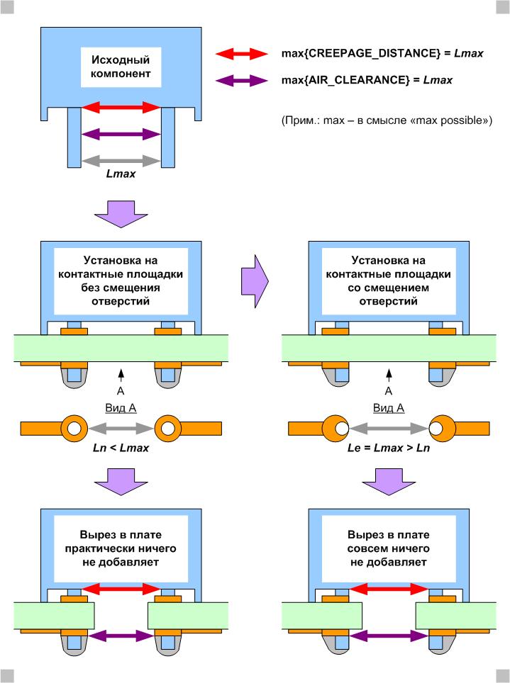
Case (1), when even in nominal (normal, initial, without taking into account the time and effects of operation) conditions, the cutout in the board either almost or does nothing at all.
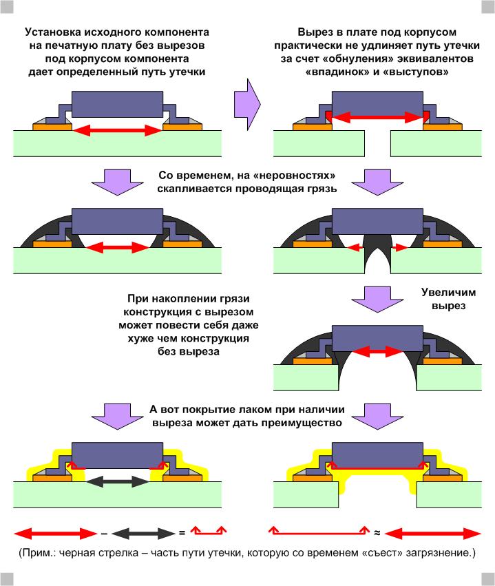
Case (2), when both nominally and in time and conditions of operation, the cut-out by itself (without taking into account the “surrounding” elements of electrical installation) may not only not improve, but also degrade the characteristics of the product.

Case (3), among other things, again showing the importance of the cut-out not by itself, but in combination with other elements of the structure, such as protective coatings (fillers) and auxiliary details (barriers).
It should be noted that the cutouts in the printed circuit board are made for other purposes that are not related to the electrical safety of the product, for example, the cutouts can relieve mechanical stresses that occur when mounting the printed circuit board in the overall design of the product. On the other hand, the purpose of the cutouts may remain less obvious in any perspective other than long-term, for example, if during testing and (or) long-term operation it turns out that the insulator (base) of the printed circuit board itself is destroyed due to moisture and [daily, seasonal , other periodic] thermocycling (heating-cooling).

The case (4), when there are two electrodes with high electric potential between them, and there is no certainty (calculated, experimental, operational) that without a cutout the printed circuit board will serve.
Instead of conclusion
PS In order not to write a separate note on the topic “What Oleg Artamonov is strictly right about,” I will say that the general promises of his second and, especially, the first article are correct and, as this would not be regrettable, extremely topical. Well, as for practical specifics, I hope this note showed that not all and not always so unequivocally.
(But the seller-foe, rather than GOST IEC 60950-1, it is much nicer to teach for GOST IEC 62850 "General requirements for equipment intended for use by children in educational institutions." Well, this is IMHO.)
P. P. S. IEC 60950-1 promise to cancel (in 2019) soon, replacing it with a new, expanded IEC 62368-1, which used to be only “for sound”, and now it will be “for IT” including . And there, you see, and GOST tightened.
Source: https://habr.com/ru/post/442294/
All Articles