STM32 fast start. Part 1 Software, Materials, Cube MX
Recently, I increasingly come across holivars on the topic of Cube MX and HAL, as applied to STM32 controllers.
On the one hand, there are defenders who like the convenience of configuration and readability of the code.
On the other hand, adherents write everything with their hands, for which the speed of work and careful use of resources are important.
')
In order to place all the dots above i - let's try to write “Hello world” by the three most frequently used paths CMSIS, LL, HAL. We estimate the costs (controller resources, the size of the executable file, and of course, the developer’s work time).
The article will consist of several parts:
STM32 fast start. Part 1 Software, materials, Cube MX.
STM32 fast start. Part 2 Hello World on HAL, debugging setup in Atollic TrueSTUDIO
STM32 fast start. Part 3 Hello World on LL
STM32 fast start. Part 4 Hello World on CMSIS
STM32 fast start. Part 5 Summary, comparison of HAL, LL, CMSIS.
First, let's define what we actually program, that is, we find the appropriate hardware.
The ideal option would be a budget board on an STM32F103C8T6 microcontroller.
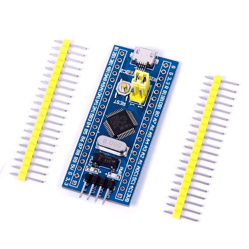
This fee can be found on the well-known site for the price of 100 Russian rubles.
Search by keywords: STM32F103C8T6 ARM STM32 Minimum
https://ru.aliexpress.com/af/STM32F103C8T6-ARM-STM32-Minimum.html?SearchText=STM32F103C8T6+ARM+STM32+Minimum
In order to fill the firmware and play with debugging - you also need a programmer
For a start, and for further use, the Chinese clone of the ST-LINK V2 programmer is perfect.
You can buy on the same site for the price of 120 Russian rubles.
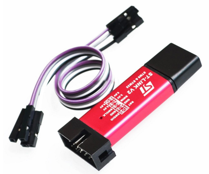
Search for ST LINK Stlink ST 252dLink V2 Mini STM8 STM32 keywords:
https://ru.aliexpress.com/af/ST-LINK-Stlink-ST%25252dLink-V2-Mini-STM8-STM32.html?SearchText=ST+LINK+Stlink+ST%252dLink+V2+Mini+STM8+ STM32
For software development under STM32, you can use different IDEs.
The most popular are IAR, Keil, Coocox (Eclipse).
We will take the path that, recently, ST itself provides absolutely free of charge and in full.
We will use Atollic TrueSTUDIO for STM32 or in common Tolik.
What are the advantages of this software: absolutely free, there is no limit on the size of the code, there is a good debugger, simple installation and configuration.
Cons: no auto add-on code.
Versions are available under windows and linux.
Downloading here https://atollic.com/resources/download/
With the installation of this software, there should be no problems, everything is intuitive, we choose where to put it and click “all the time” next time.
After installation, you can not run, because in addition to the IDE itself, something else is needed.
If all the same run - just close.
Since TrueSTUDIO is a development and debugging tool, I would like not to build the project with my hands (connecting the required libraries and prescribing paths), but to get some pre-configured file in which you can immediately write code without unnecessary problems.
To do this, use the program code generator Cube MX or in common "Kalokub".
This software is the first stumbling block in holivarah what to write under STM: on registers and CMSIS or on HAL.
Defenders of the first ideology give the following arguments: Cube MX generates a huge, unnecessary amount of code, which also slows down the work of the MC.
The defenders of the second state that the automatically generated code reduces development time, allowing the developer to switch to the device's core part (to the main logic) faster, giving the routine configuration of the periphery to the specialized software (Cube MX).
Oddly enough, both of these ideologies are true and applicable in practice, but only each in its own terms.
Let's look at a couple of examples:
Example No. 1: It is required to develop a device that is as cheap as possible, since it is planned to manufacture in batches of 100,500 pieces each year. Naturally, every extra ruble of the price of a device will result in hundreds of thousands of rubles of expenses on the final device. At the same time, in the planned development there are a couple of heavy calculations and work with peripherals (ADC, SPI, UART) at maximum speeds.
The device is a completely autonomous product, in the future minimal changes are planned for the entire period of production of this equipment. The development period to obtain the finished sample is 1-2 years.
Example No. 2: A prototype device is required that may be of interest to the customer and he will order 100 pieces of similar devices for the conversion of his object. The first planned batch must be shipped to the customer in 2 months. The size of the first test batch of 10 pcs.
The exact terms of reference will be corrected in the course of working on the project, but it is known that in the future several reworkings of the hardware are planned, under which it is necessary to quickly adjust all the applied logic.
In the first example, the ideal option would be to select the cheapest controller and write a hardware dependent, but optimal code, where work with the periphery will be organized through access to the corresponding registers (CMSIS). The developer who is engaged in this project - must have good or excellent knowledge of the periphery of a particular family of MK. Ideally, when you try to wake him up at night, you should immediately call the address of the desired vector from the interrupt vector table.
In the second example, the choice of controller is determined by the available iron, as well as the time spent on writing the functionality required by the customer. Therefore, the speed and optimization of the software itself fades into the background. There is no time for manual initialization, as there is no time for elaboration of hardware dependencies.
In this case, the controller is selected, which can be quickly put into production in the current region, initialization is done on it using the Cube MX, application logic is written to HAL and the prototype is transferred to the customer for testing. Such a project can lead any average developer who has learned the skills of working with the target programming language. The understanding of the subtleties of the work of the periphery is practically not required.
No matter how sad it may sound - in the realities of modern device development in Russia - the example number 1 is encountered less and less, passing the baton to the example number 2.
We will return to the discussion of examples 1 and 2 at the very end of the series of articles, and now we will continue with the preparation of the working space.
At this stage, we will make a short pause, go to the website my.st.com and register an account on it, since the policy of ST does not allow you to download the necessary materials without registration.
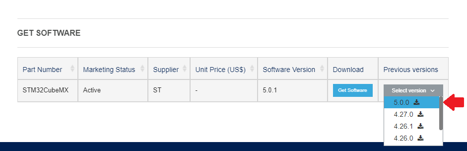
Once we have access to the site - download the STM32 Cube MX.
At the very bottom of the page there is a version selection button, we need version 5.0.0
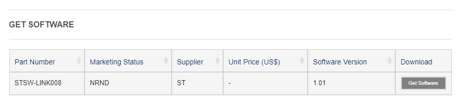
Along the way, until we left here, download two more things that will be useful later
https://www.st.com/en/development-tools/stsw-link008.html
Driver ST-LINK V2
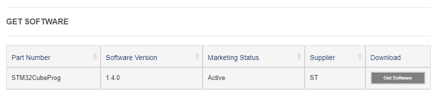
and https://www.st.com/en/development-tools/stm32cubeprog.html
The program flasher.
Installing the driver, flash driver and the Cub itself doesn’t cause any difficulties, just agree with everything and click further.
After the full installation of the necessary software - we can begin to create the project.
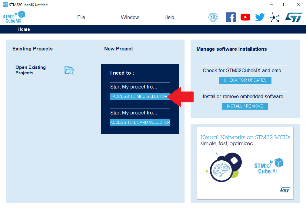
To do this, run Cube MX.
In the window that appears, click on the button "ACCESS TO MCU SELECTOR".
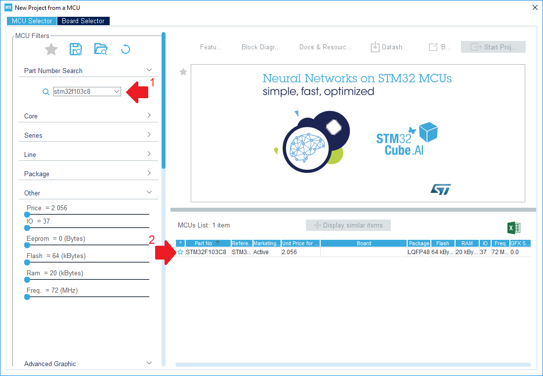
Our target board is equipped with an STM32F103C8T6 microcontroller.
We will enter its name in the search bar and double-click on the only option found.
In the same table you can see the main stuffing of our MK (64 kilobytes of flash, 20 kilobytes of operatives, etc.).
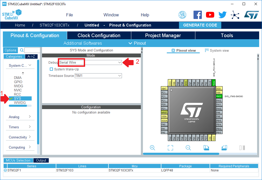
Before us appeared a schematically depicted controller case with legs spread apart.
At this stage, it is imperative to choose the debugger connection method.
To do this, on the Pinout & Configuration tab in the left menu, select the SYS item and in the drop-down list called “Debug” set the value to Serial Wire.
At the same time, we notice from the corner of our eye that the program reserved two pins on the controller mnemonic for debugging purposes.
Once again we remember that we want to flash the LED on our board.
To do this, you must first find out which leg it is connected to.
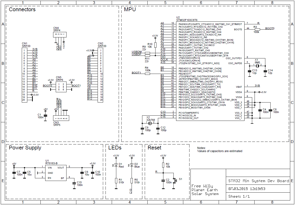
This will help us schematic electrical diagram:
or more colorful and easy to understand pinout boards
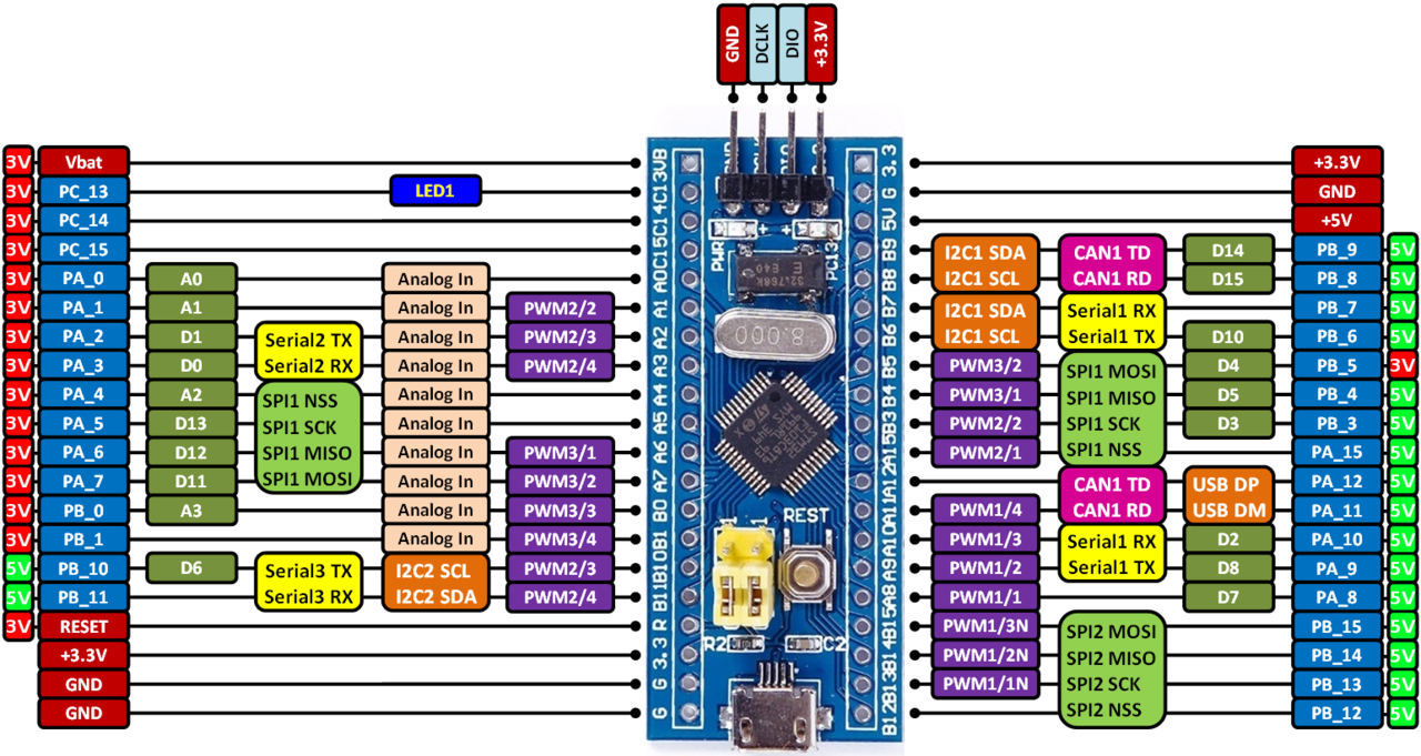
The desired LED is on the PC13 foot.
Accordingly, it is necessary to configure this output to work in the output mode.
For this:
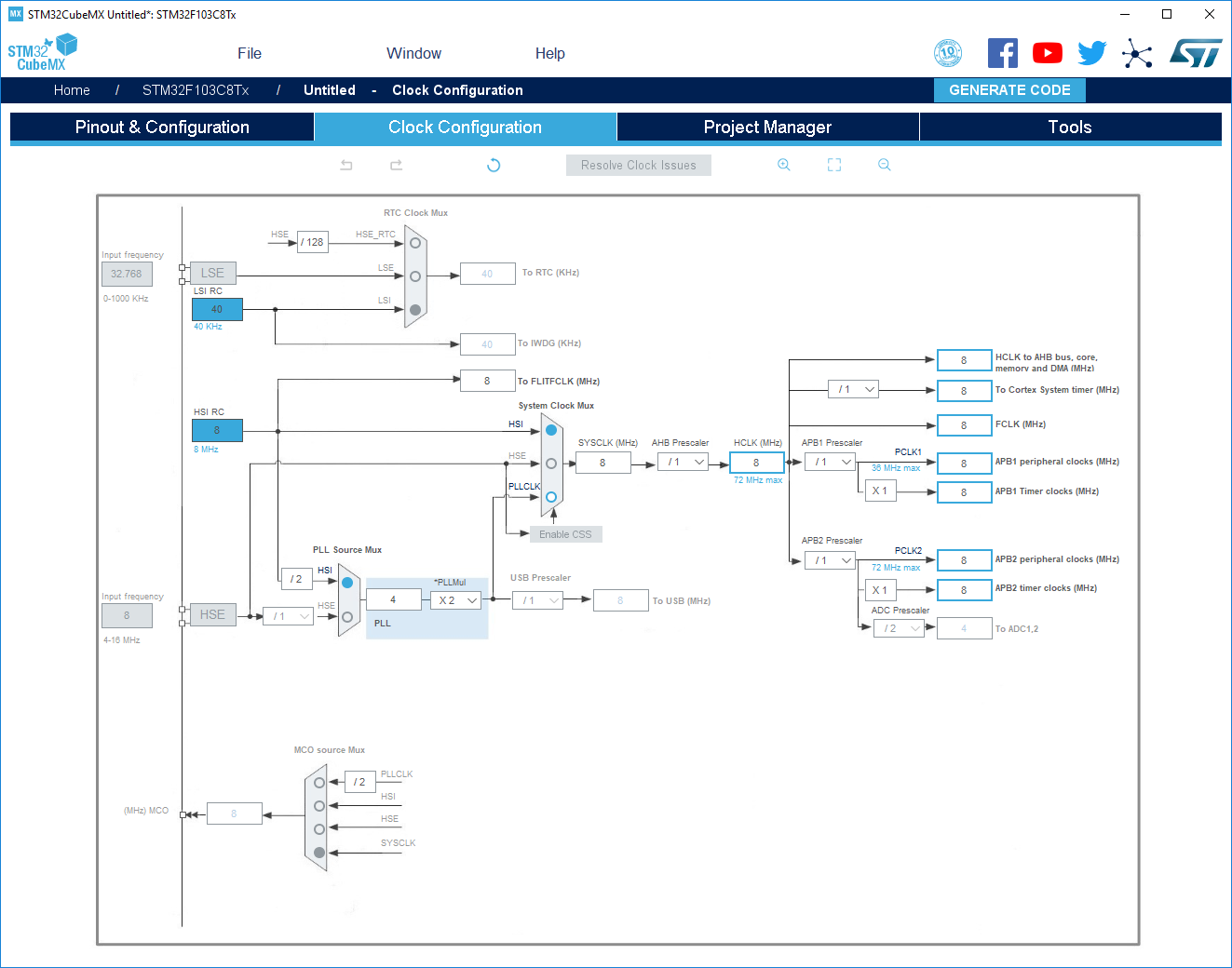
Continue setting up the project, go to the Clock Configuration tab.
In fact, this is one of the most important tabs, which allows you to configure the peripheral clocking parameters, but for now let's not touch anything here, since the main goal at the moment is not that.
Go to the Project Manager tab, under the Project tab.
Be sure to fill in the following parameters:
We get down below, under the tab Code Generator.
Here we must mark the option Generate peripheral initialization as pair ...
Thus, we obtain a more structured project in which each type of periphery has its own pair of C and H files.
Stayed last step. Advanced Settings subtab.
During the initial launch, you may need to download the current version of the library for the selected MK family.
We agree to download files:
We are going to warm the kettle or make coffee:
After the completion of the kodo-generator, we immediately open it:
Choose any folder where Atollic will store the workspace:
If opened successfully, we will see the main Atollic TrueSTUDIO for STM window.
The general information interests us a little, therefore we will pass at once to a tree of files.
Find the main.c file there and the int main (void) function:
For self-test - try to build an empty project.
Continuation - in the following part.
PS: Previously published an article in his personal blog .
On the one hand, there are defenders who like the convenience of configuration and readability of the code.
On the other hand, adherents write everything with their hands, for which the speed of work and careful use of resources are important.
')
In order to place all the dots above i - let's try to write “Hello world” by the three most frequently used paths CMSIS, LL, HAL. We estimate the costs (controller resources, the size of the executable file, and of course, the developer’s work time).
The article will consist of several parts:
STM32 fast start. Part 1 Software, materials, Cube MX.
STM32 fast start. Part 2 Hello World on HAL, debugging setup in Atollic TrueSTUDIO
STM32 fast start. Part 3 Hello World on LL
STM32 fast start. Part 4 Hello World on CMSIS
STM32 fast start. Part 5 Summary, comparison of HAL, LL, CMSIS.
First, let's define what we actually program, that is, we find the appropriate hardware.
The ideal option would be a budget board on an STM32F103C8T6 microcontroller.
This fee can be found on the well-known site for the price of 100 Russian rubles.
Search by keywords: STM32F103C8T6 ARM STM32 Minimum
https://ru.aliexpress.com/af/STM32F103C8T6-ARM-STM32-Minimum.html?SearchText=STM32F103C8T6+ARM+STM32+Minimum
In order to fill the firmware and play with debugging - you also need a programmer
For a start, and for further use, the Chinese clone of the ST-LINK V2 programmer is perfect.
You can buy on the same site for the price of 120 Russian rubles.
Search for ST LINK Stlink ST 252dLink V2 Mini STM8 STM32 keywords:
https://ru.aliexpress.com/af/ST-LINK-Stlink-ST%25252dLink-V2-Mini-STM8-STM32.html?SearchText=ST+LINK+Stlink+ST%252dLink+V2+Mini+STM8+ STM32
For software development under STM32, you can use different IDEs.
The most popular are IAR, Keil, Coocox (Eclipse).
We will take the path that, recently, ST itself provides absolutely free of charge and in full.
We will use Atollic TrueSTUDIO for STM32 or in common Tolik.
What are the advantages of this software: absolutely free, there is no limit on the size of the code, there is a good debugger, simple installation and configuration.
Cons: no auto add-on code.
Versions are available under windows and linux.
Downloading here https://atollic.com/resources/download/
With the installation of this software, there should be no problems, everything is intuitive, we choose where to put it and click “all the time” next time.
After installation, you can not run, because in addition to the IDE itself, something else is needed.
If all the same run - just close.
Since TrueSTUDIO is a development and debugging tool, I would like not to build the project with my hands (connecting the required libraries and prescribing paths), but to get some pre-configured file in which you can immediately write code without unnecessary problems.
To do this, use the program code generator Cube MX or in common "Kalokub".
This software is the first stumbling block in holivarah what to write under STM: on registers and CMSIS or on HAL.
Defenders of the first ideology give the following arguments: Cube MX generates a huge, unnecessary amount of code, which also slows down the work of the MC.
The defenders of the second state that the automatically generated code reduces development time, allowing the developer to switch to the device's core part (to the main logic) faster, giving the routine configuration of the periphery to the specialized software (Cube MX).
Oddly enough, both of these ideologies are true and applicable in practice, but only each in its own terms.
Let's look at a couple of examples:
Example No. 1: It is required to develop a device that is as cheap as possible, since it is planned to manufacture in batches of 100,500 pieces each year. Naturally, every extra ruble of the price of a device will result in hundreds of thousands of rubles of expenses on the final device. At the same time, in the planned development there are a couple of heavy calculations and work with peripherals (ADC, SPI, UART) at maximum speeds.
The device is a completely autonomous product, in the future minimal changes are planned for the entire period of production of this equipment. The development period to obtain the finished sample is 1-2 years.
Example No. 2: A prototype device is required that may be of interest to the customer and he will order 100 pieces of similar devices for the conversion of his object. The first planned batch must be shipped to the customer in 2 months. The size of the first test batch of 10 pcs.
The exact terms of reference will be corrected in the course of working on the project, but it is known that in the future several reworkings of the hardware are planned, under which it is necessary to quickly adjust all the applied logic.
In the first example, the ideal option would be to select the cheapest controller and write a hardware dependent, but optimal code, where work with the periphery will be organized through access to the corresponding registers (CMSIS). The developer who is engaged in this project - must have good or excellent knowledge of the periphery of a particular family of MK. Ideally, when you try to wake him up at night, you should immediately call the address of the desired vector from the interrupt vector table.
In the second example, the choice of controller is determined by the available iron, as well as the time spent on writing the functionality required by the customer. Therefore, the speed and optimization of the software itself fades into the background. There is no time for manual initialization, as there is no time for elaboration of hardware dependencies.
In this case, the controller is selected, which can be quickly put into production in the current region, initialization is done on it using the Cube MX, application logic is written to HAL and the prototype is transferred to the customer for testing. Such a project can lead any average developer who has learned the skills of working with the target programming language. The understanding of the subtleties of the work of the periphery is practically not required.
No matter how sad it may sound - in the realities of modern device development in Russia - the example number 1 is encountered less and less, passing the baton to the example number 2.
We will return to the discussion of examples 1 and 2 at the very end of the series of articles, and now we will continue with the preparation of the working space.
At this stage, we will make a short pause, go to the website my.st.com and register an account on it, since the policy of ST does not allow you to download the necessary materials without registration.
Once we have access to the site - download the STM32 Cube MX.
At the very bottom of the page there is a version selection button, we need version 5.0.0
Along the way, until we left here, download two more things that will be useful later
https://www.st.com/en/development-tools/stsw-link008.html
Driver ST-LINK V2
and https://www.st.com/en/development-tools/stm32cubeprog.html
The program flasher.
Installing the driver, flash driver and the Cub itself doesn’t cause any difficulties, just agree with everything and click further.
After the full installation of the necessary software - we can begin to create the project.
To do this, run Cube MX.
In the window that appears, click on the button "ACCESS TO MCU SELECTOR".
Our target board is equipped with an STM32F103C8T6 microcontroller.
We will enter its name in the search bar and double-click on the only option found.
In the same table you can see the main stuffing of our MK (64 kilobytes of flash, 20 kilobytes of operatives, etc.).
Before us appeared a schematically depicted controller case with legs spread apart.
At this stage, it is imperative to choose the debugger connection method.
To do this, on the Pinout & Configuration tab in the left menu, select the SYS item and in the drop-down list called “Debug” set the value to Serial Wire.
At the same time, we notice from the corner of our eye that the program reserved two pins on the controller mnemonic for debugging purposes.
Once again we remember that we want to flash the LED on our board.
To do this, you must first find out which leg it is connected to.
This will help us schematic electrical diagram:
or more colorful and easy to understand pinout boards
The desired LED is on the PC13 foot.
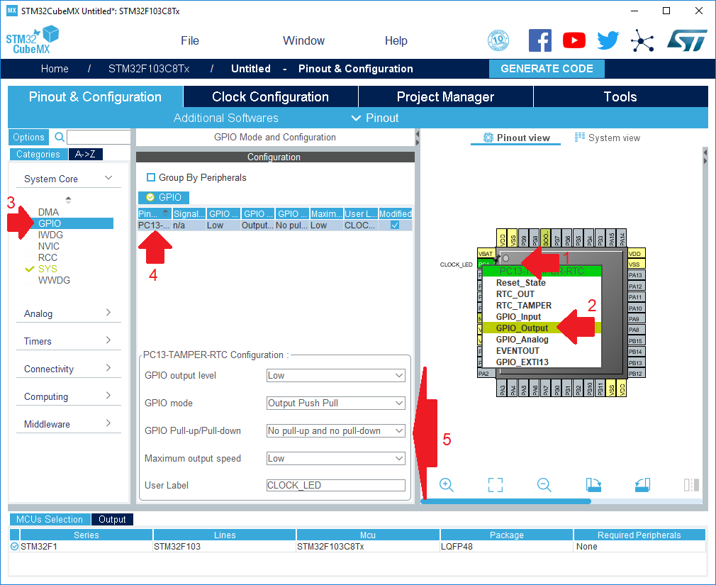
Accordingly, it is necessary to configure this output to work in the output mode.
For this:
- Find the conclusion on the mnemonic
- Click on it with the right mouse button, from the drop-down menu, select the item "GPIO_Output"
- Go to the GPIO menu,
- In the list, select PC13
- Fill in the PC13-TAMPER-RTC Configuration table in accordance with the screenshot, especially we are interested in the parameters GPIO mode and User Label
Continue setting up the project, go to the Clock Configuration tab.
In fact, this is one of the most important tabs, which allows you to configure the peripheral clocking parameters, but for now let's not touch anything here, since the main goal at the moment is not that.
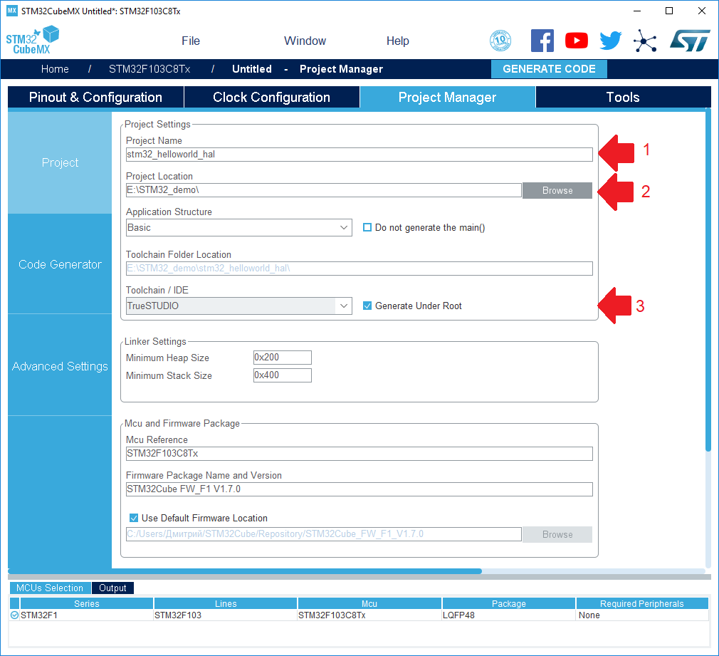
Go to the Project Manager tab, under the Project tab.
Be sure to fill in the following parameters:
- Project name (it is better to use only Latin letters)
- The directory in which the project will be created (it is also better to use only the Latin alphabet)
- IDE, which is planned to work on the project (we plan to use TrueSTUDIO)
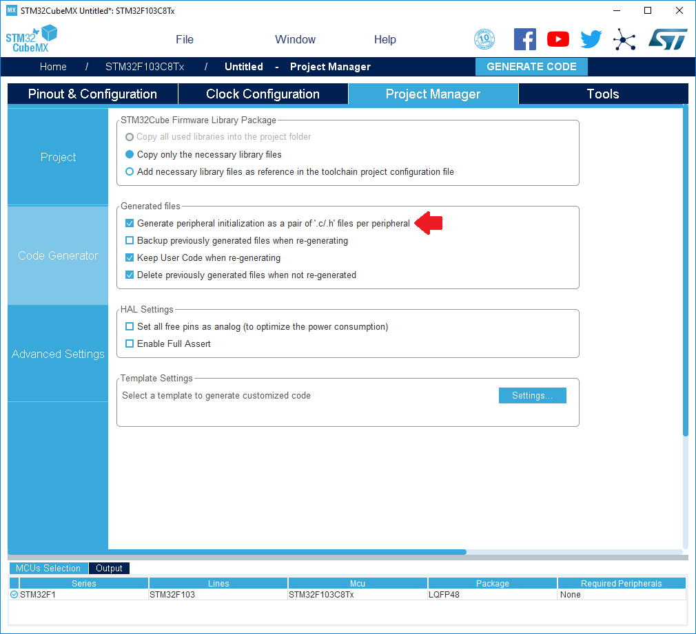
We get down below, under the tab Code Generator.
Here we must mark the option Generate peripheral initialization as pair ...
Thus, we obtain a more structured project in which each type of periphery has its own pair of C and H files.
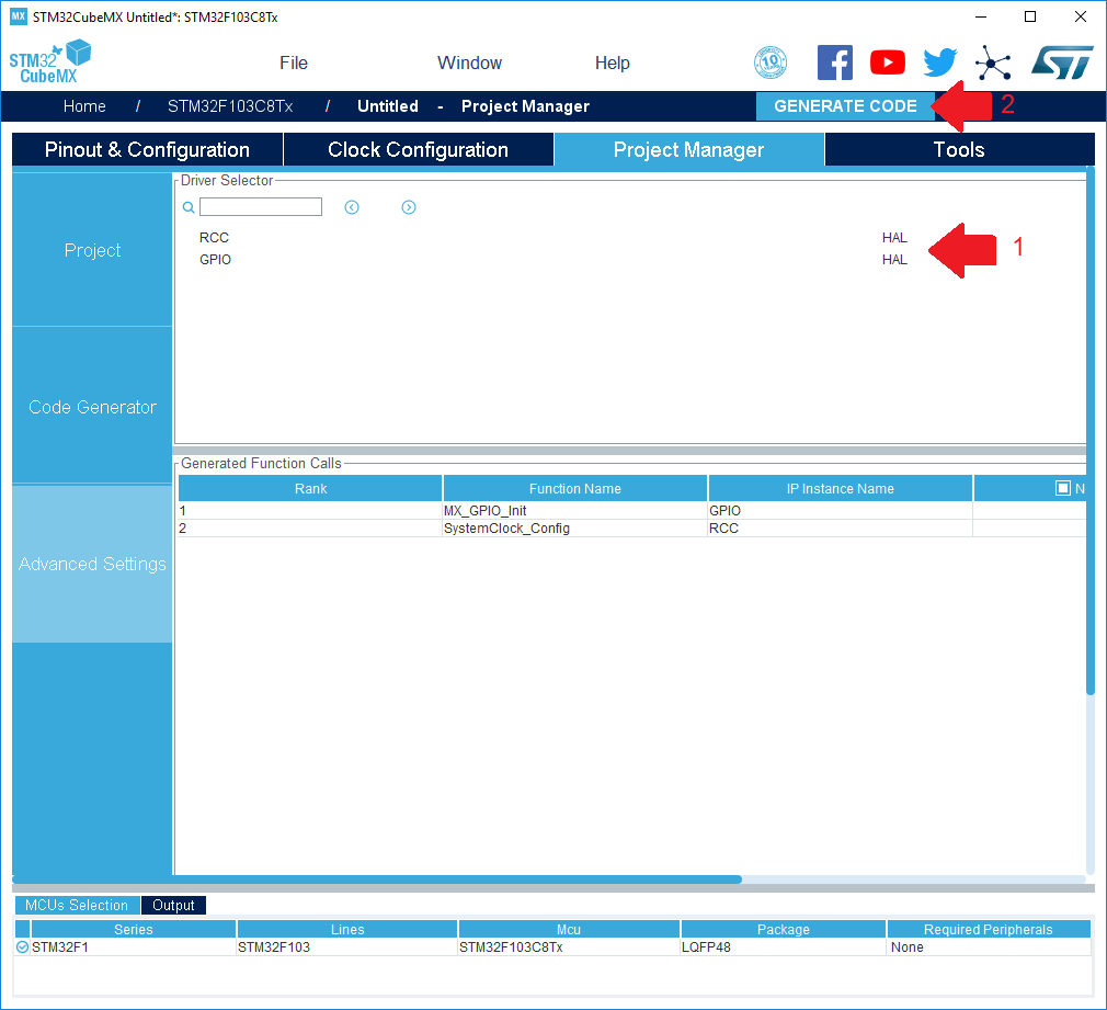
Stayed last step. Advanced Settings subtab.
- Select the type of HAL library for all peripheral modules.
- Build project with current settings
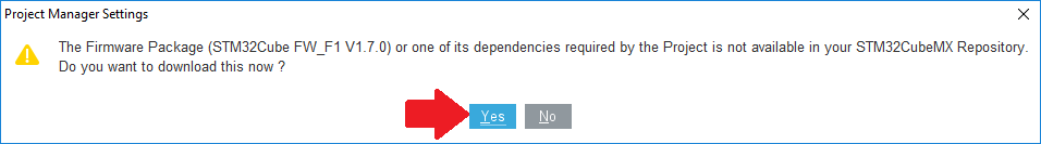
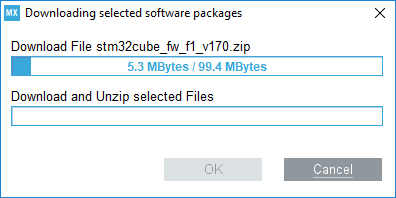
During the initial launch, you may need to download the current version of the library for the selected MK family.
We agree to download files:
We are going to warm the kettle or make coffee:
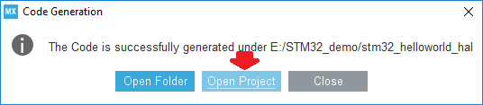
After the completion of the kodo-generator, we immediately open it:
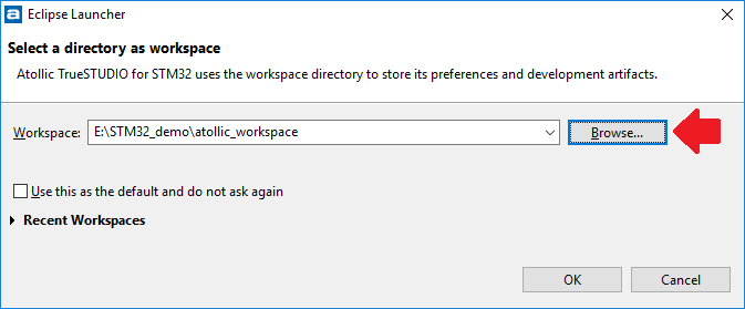
Choose any folder where Atollic will store the workspace:
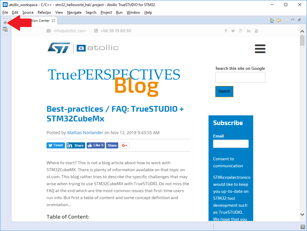
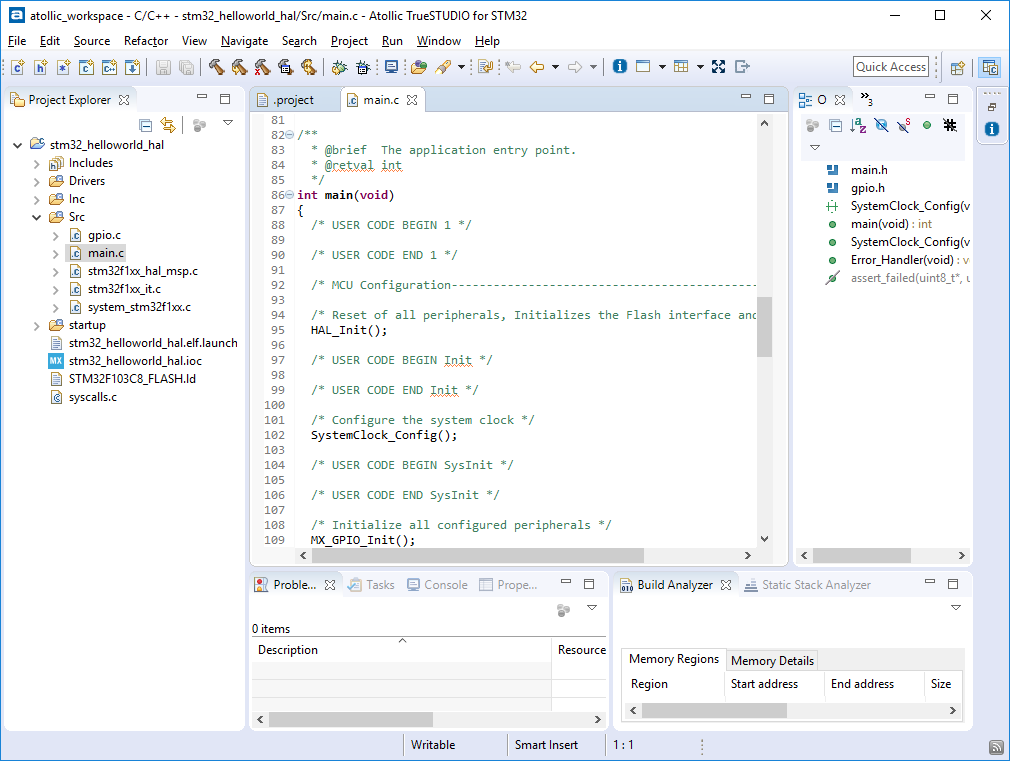
If opened successfully, we will see the main Atollic TrueSTUDIO for STM window.
The general information interests us a little, therefore we will pass at once to a tree of files.
Find the main.c file there and the int main (void) function:
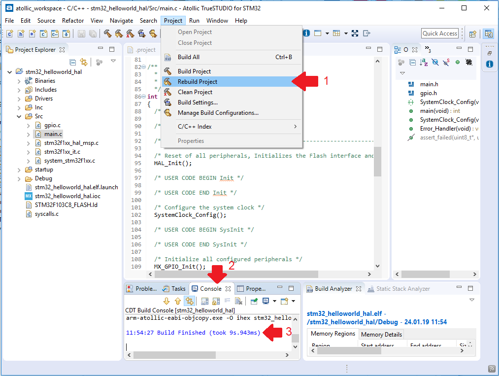
For self-test - try to build an empty project.
- In the menu Project -> Rebuild Project
- At the bottom, select the Console tab.
- With a successful build, you should get the text Build Finished
Continuation - in the following part.
PS: Previously published an article in his personal blog .
Source: https://habr.com/ru/post/442162/
All Articles