On the issue of batteries
If on the cage of an elephant read the inscription: buffalo, - do not believe your eyes
In one product under development, a significant-capacity rechargeable battery was used from several parallel sections with six cans of LiIon rechargeable cells of the “1s1p MP 176065 IntegrationTM” type for 6000 mAh manufactured by Saft each. One battery returned to us for repair and I decided to assess the degree of balance of individual cans after prolonged use. To do this, it was necessary to disengage the banks, charge them separately and estimate the spread of the charge taken.
But first I decided to look at the voltage on the section as a whole, expecting to see zero, because any discharged bank disconnects itself from the consumer circuit, and we must either see a voltage of at least 6 * 2.4V = 14.4V, or nothing.
What was my amazement when 12V was found on one section, and 7B on the other (I will not write Volta any more and not because of lack of respect for the great Italian, but because of laziness).
The result is somewhat discouraging, we continue research and measure each bank in the section for 12 - for four expected voltage of 2.8-3.2, for two - 0, in total, everything is the same, but why it is 0 on disconnected cells, and not a circuit break - is unclear.
')
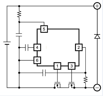
Okay, I assume that a circuit breakdown takes place, but it is not absolute, there is a small current through the control circuit, because it does not disconnect from external contacts - look at the circuit (it is located at the end of the post, otherwise the whole intrigue disappears).
We connect the load to the section in the form of a 1k resistor (current 7mA), the output voltage drops slightly to 11.8, which means that the internal resistance of the control circuit is of the order of 0.2 / 7E-3 = 200/7 ~ 30 Ohm, as it is not enough resistance, I counted on a ten kilo , but maybe it is nonlinear, although it is still strange. We increase the current to 50mA, the voltage drops to 11.6, which corresponds to a resistance of 0.4 / 50E-3 = 400/50 = 20, we increase the current to 100mA, the voltage practically does not change, which already gives 10 Ohms.
Indeed, the resistance is nonlinear, but it is clearly bent in the wrong direction. Most of all it looks like a direct branch of the VAC diode, but where it comes from is incomprehensible. Okay, remove the protective film from the battery and remove the protection board (you understand that without it, the battery can not be used if you are not extreme). We see a typical circuitry of two transistors and a voltage control chip, but on the reverse side of the board we observe a large element labeled STPS104B.
Yeah, this is a Schottky diode, connected back to the polarity of the battery, that's where the voltage drop of ~ 0.2 per cell is practically independent of the current (at low currents). The riddle is solved, it was easy, now we have to evaluate the technical solution of a well-known company.
The first - a definite plus - this scheme allows you to continue to draw energy from the section, even if one cell is completely discharged. In this case, the total voltage will drop by 2.4 (the minimum allowable per cell) + (0.2 ÷ 0.6) <= 3, but this is better than a complete shutdown, although nuances are possible.
The second - a weak minus - diodes in general, and Schottky in particular, have a reverse current, which will be a parasitic load and will reduce the available power of the cell. In this particular case, the reverse current will be no more than 100 μA (under normal conditions), that is, we will lose 0.1 * 24 = 2.4 mAh ~ 0.04% of capacity per day of storage of the cell, very little compared to self-discharge of ~ 0.5%. By the way, the self-discharge current in the documentation for the cell is simply not indicated, I invent it out of general considerations and recommendations for recharging the cells during long-term storage once every 6 months.
The third one is an invented minus - if during the process of charging all cells simultaneously decide that they have reached the required level and disconnect from external terminals to prevent overcharging (not a very likely event, but still), the input voltage of the charger will be attached to the series circuit of back-on diodes and it may well be on one of them, which limits the charging voltage to the breakdown value for the reverse diode of 45 and, accordingly, the number of cells in section 45 / 4.2 = 10. Although I am not quite right about inventiveness - if all cells are completely discharged (and this is possible) and disconnected from external terminals, then at the moment of the start of charge there will be a similar situation, although not for long, therefore certain voltage limits should be specified .
But the fourth - undoubtedly a minus - the complete absence of an indication of the presence of such a circuit solution in the documentation for the device. Well, you can not do this, this is a significant feature of the device and it should be reflected in the ED. Although, probably, this is how they taught me, and in modern engineering practice, such considerations are taken to be neglected. In the end, I do not have a company of the SAFT level, and those who produce these cells with such documentation have and they feel good in the market. And what do you think? - poll at the end of the post.
Well, actually, on the research topic, it turned out that after ~ 100 charge cycles (without balancing) and discharge (taking into account the above features) the residual charge spread in individual cells was 12%, the figure is not negligible, but I expected the worst, so offset
Let us estimate the possible efficiency of the standard passive balancing scheme, for which we take the current through the ballast resistor of 50 mA (standard value for Chinese devices), then when charging with the recommended current of 0.2 C and charging time of not more than 7 hours, we get a possible reduction of the cell charge of 50 * 7 = 350 mAh, which corresponds to approximately 5% of the declared capacity. In fact, of course, much less, since the shunt will turn on at constant voltage mode, but you still need to get to it, so this is a top estimate, but at least something.
Then we can assume that the above-indicated cell capacitance can be compensated for in 5-10 charge cycles with balancing. That is, if we make the balancing of the non-integral part of the section, we can expect that the negative effects can be fully compensated for in each cycle for these cells. Of course, all this is just a rough estimate and an exact answer to the question about balancing possibilities requires additional research.
And here is the promised scheme:
Source: https://habr.com/ru/post/442102/
All Articles