Construction of the metal frame of the building using the program SPDS Metal structures
One of the main tasks of modern design is the search for new planning solutions for buildings with maximum internal space. It is not difficult to guess that it is the design of a building from a metal frame that makes it possible to implement this idea. Therefore, metal frameworks of buildings are not only an actual topic for the designer, but also a progressive solution in the design and construction of any objects.
But how to implement the idea and turn it into a finished project? With this we can help to cope with specialized software SPDS Metal. This is a vertical application that is installed on platforms such as AutoCAD and nanoCAD ( SDS Metal Structures and nanoCAD SDS Metal Structures ). SPDS Steel Structures is a universal program designed to develop two-dimensional drawings of metal structures of the KM and AS grades.
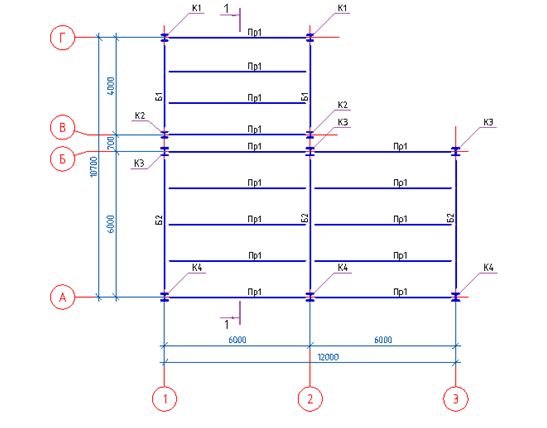
The creation of a building framework project usually begins with the creation of a plan for the arrangement of metal structures. To do this, the program provides all the necessary tools for creating a grid of axes and the elements of the metal frame.

')
In the process of creating a project, the most frequently used commands are “Column” and “Gully” - these are the basic tools of the program that are needed to build the elements of the metal frame of a building. Each tool has a large set of parameters that are set by the user directly through the dialog box of the selected command. The program remembers all the parameters previously entered for a specific brand of an element, and the next time you create an element, you do not have to enter these parameters.

Having established for each structural element its own parameters, it remains only to place them on the plan. Marking of elements occurs automatically, which significantly speeds up the process of drawing design.
In the design quite often there are such moments when it is necessary to urgently make changes to the structural elements. One of the key features of the program is the ability to automatically adjust the parameters for a group of elements of the same brand. For example, to change the profile size or steel material, you do not need to change it on every single element; this can be done on one of the elements and all the adjustments made will be applied to the entire group of elements. Due to this possibility, the process of editing structural elements can be performed in a matter of seconds.
After completing the work with the plan, the next design stage is the creation of vertical longitudinal and transverse sections. There are several ways to build cuts. The easiest way is applied in our project: when the frame elements are created with previously created marks, but with a different kind of display. For beams and columns, the view was changed to the “Front” view, and for the runs, the “Section” view was set. A cross section of the metal frame was constructed with these species.
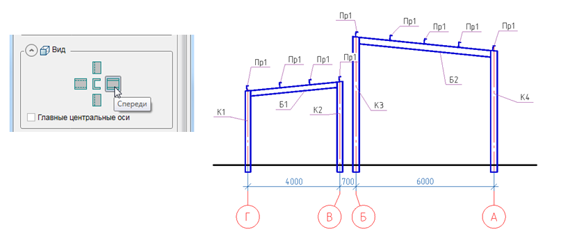
The project initially envisaged the installation of lightweight enclosing structures made of sandwich panels; for this purpose, the beams and frame joists were designed with a slope recommended by the manufacturer of the roofing panels. According to the skeleton scheme, the extreme runs run directly onto the columns, and for proper installation of the runs, the trimming of the tips of the columns must be performed with an exposure of this slope. It is worth noting that all the necessary trimming is best done immediately on the cut: this will save you from further trimming of these elements in the nodes.

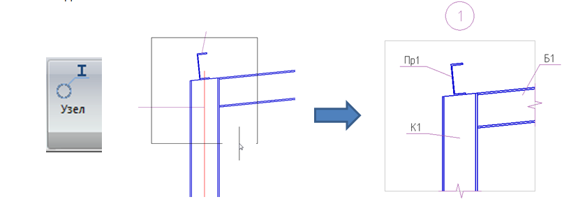
When the cuts are ready, it is necessary to create junctions of metal structures between them. Nodes in the drawings lead, when it is necessary to show the fundamental details of the connection elements of the supporting structures, and then on their basis to create detailed drawings.
In the program SPDS Metalware there is a separate team to create nodes, the “Knot” team. The principle of its operation is very simple. The section selects the required conjugation of structures for which it is necessary to create a node, then, following a command, cut and copy the selected fragment onto the drawing sheet. Immediately after insertion, the node is automatically numbered and the elements are marked. Further, the user needs only to adjust the location of the lines of breakage, positional callouts and add connecting elements.
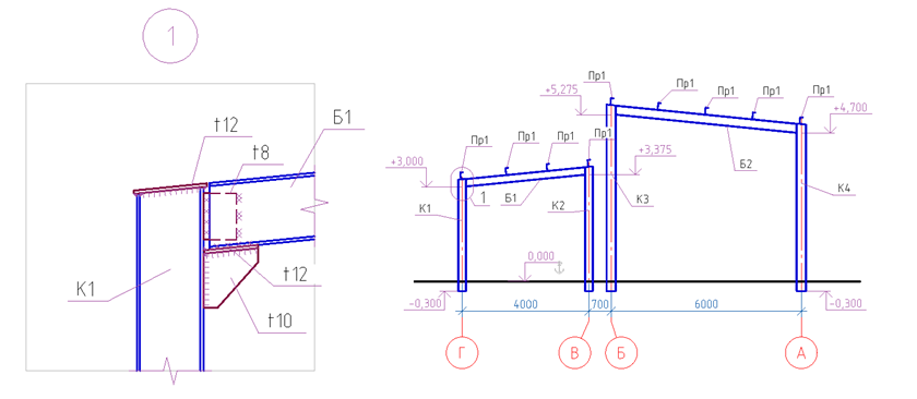
In order to realize the installation clearance, using the “Profile Trimming” command, the end of beam B1 is trimmed. Further, the detailing of the assembly is supplemented with supporting elements made of plates; for this purpose, using the “Plate” command, a support table, a column head and a connecting plate are created.

An important advantage is the presence in the program of an already integrated module SPDS , which will help you to prepare the documentation in a quality manner and in accordance with the requirements of GOST.

With the help of the “Level mark” command, the elevations at the points of support of beams are shown on the sections. And with the help of the “Welded Seam” command on the nodes, in the joints of the structures, angular mounting and factory welds are shown according to the standard GOST 21.502-2016.
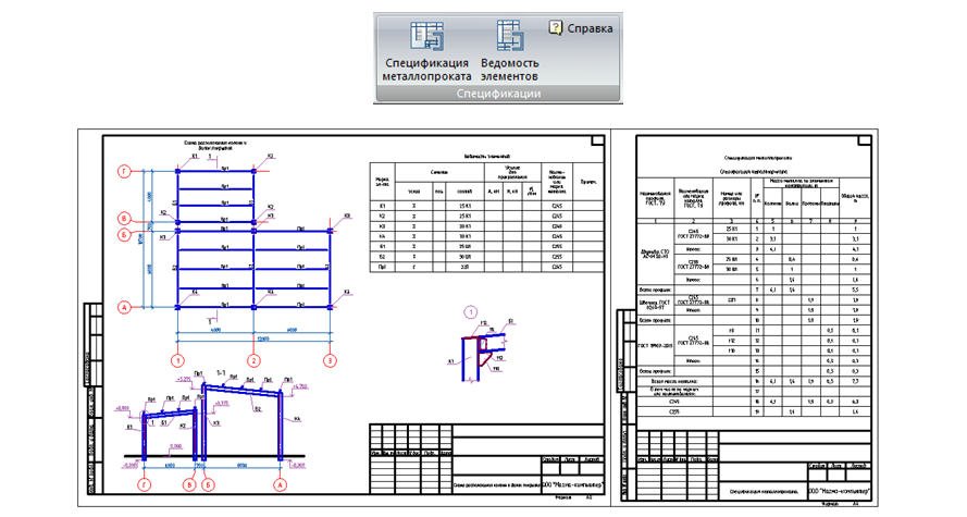
To facilitate the reading of the drawings, the correct arrangement of the images of the structural elements on the sheet format is necessary. Using the Formats SPDS tool, you can choose the format we need by placing structural elements on the left side of the sheet, and leave the right side free for specification.

The final stage in the project is the creation of specifications for the elements of metal structures. To do this, the toolbar has two commands to display the necessary specifications. Specifications are easily and without any settings generated, the mass of metal is automatically calculated and the user only needs to place them on the sheet format.
In conclusion, I would like to note that with the help of the SPDS Metalware program, you can carry out projects not only for simple structures, but also for buildings with complex shapes. Work in this program is simple and does not require any special skills from the user. The output project documentation is saved in the common dwg format and is supported by many CAD applications. Thus, SPDS Metalware is not only a simple and convenient solution for creating two-dimensional drawings of metal structures, but also a guarantee of the quality of the produced project documentation.
You can get acquainted in more detail with the functionality of the SPDS Metalware program on the Magma computer channel on YouTube or on the SPDS project website .
But how to implement the idea and turn it into a finished project? With this we can help to cope with specialized software SPDS Metal. This is a vertical application that is installed on platforms such as AutoCAD and nanoCAD ( SDS Metal Structures and nanoCAD SDS Metal Structures ). SPDS Steel Structures is a universal program designed to develop two-dimensional drawings of metal structures of the KM and AS grades.
The creation of a building framework project usually begins with the creation of a plan for the arrangement of metal structures. To do this, the program provides all the necessary tools for creating a grid of axes and the elements of the metal frame.
')
In the process of creating a project, the most frequently used commands are “Column” and “Gully” - these are the basic tools of the program that are needed to build the elements of the metal frame of a building. Each tool has a large set of parameters that are set by the user directly through the dialog box of the selected command. The program remembers all the parameters previously entered for a specific brand of an element, and the next time you create an element, you do not have to enter these parameters.
Having established for each structural element its own parameters, it remains only to place them on the plan. Marking of elements occurs automatically, which significantly speeds up the process of drawing design.
In the design quite often there are such moments when it is necessary to urgently make changes to the structural elements. One of the key features of the program is the ability to automatically adjust the parameters for a group of elements of the same brand. For example, to change the profile size or steel material, you do not need to change it on every single element; this can be done on one of the elements and all the adjustments made will be applied to the entire group of elements. Due to this possibility, the process of editing structural elements can be performed in a matter of seconds.
After completing the work with the plan, the next design stage is the creation of vertical longitudinal and transverse sections. There are several ways to build cuts. The easiest way is applied in our project: when the frame elements are created with previously created marks, but with a different kind of display. For beams and columns, the view was changed to the “Front” view, and for the runs, the “Section” view was set. A cross section of the metal frame was constructed with these species.
The project initially envisaged the installation of lightweight enclosing structures made of sandwich panels; for this purpose, the beams and frame joists were designed with a slope recommended by the manufacturer of the roofing panels. According to the skeleton scheme, the extreme runs run directly onto the columns, and for proper installation of the runs, the trimming of the tips of the columns must be performed with an exposure of this slope. It is worth noting that all the necessary trimming is best done immediately on the cut: this will save you from further trimming of these elements in the nodes.
When the cuts are ready, it is necessary to create junctions of metal structures between them. Nodes in the drawings lead, when it is necessary to show the fundamental details of the connection elements of the supporting structures, and then on their basis to create detailed drawings.
In the program SPDS Metalware there is a separate team to create nodes, the “Knot” team. The principle of its operation is very simple. The section selects the required conjugation of structures for which it is necessary to create a node, then, following a command, cut and copy the selected fragment onto the drawing sheet. Immediately after insertion, the node is automatically numbered and the elements are marked. Further, the user needs only to adjust the location of the lines of breakage, positional callouts and add connecting elements.
In order to realize the installation clearance, using the “Profile Trimming” command, the end of beam B1 is trimmed. Further, the detailing of the assembly is supplemented with supporting elements made of plates; for this purpose, using the “Plate” command, a support table, a column head and a connecting plate are created.
An important advantage is the presence in the program of an already integrated module SPDS , which will help you to prepare the documentation in a quality manner and in accordance with the requirements of GOST.
With the help of the “Level mark” command, the elevations at the points of support of beams are shown on the sections. And with the help of the “Welded Seam” command on the nodes, in the joints of the structures, angular mounting and factory welds are shown according to the standard GOST 21.502-2016.
To facilitate the reading of the drawings, the correct arrangement of the images of the structural elements on the sheet format is necessary. Using the Formats SPDS tool, you can choose the format we need by placing structural elements on the left side of the sheet, and leave the right side free for specification.
The final stage in the project is the creation of specifications for the elements of metal structures. To do this, the toolbar has two commands to display the necessary specifications. Specifications are easily and without any settings generated, the mass of metal is automatically calculated and the user only needs to place them on the sheet format.
In conclusion, I would like to note that with the help of the SPDS Metalware program, you can carry out projects not only for simple structures, but also for buildings with complex shapes. Work in this program is simple and does not require any special skills from the user. The output project documentation is saved in the common dwg format and is supported by many CAD applications. Thus, SPDS Metalware is not only a simple and convenient solution for creating two-dimensional drawings of metal structures, but also a guarantee of the quality of the produced project documentation.
You can get acquainted in more detail with the functionality of the SPDS Metalware program on the Magma computer channel on YouTube or on the SPDS project website .
Source: https://habr.com/ru/post/442098/
All Articles