Stylish waterfall from RiME in the game engine: make the water flow
This is the second (and last) part of the waterfall creation guide in Unity or UE4 after being inspired by the RiME game. In the first, we dealt with the tools, chose the development environment and created a circle shader on the water. Why did you start with this? It's simple: it uses most of the methods that are now needed when creating a waterfall. But here there are also hints. We will not pull - let's under the cat.

Let's start with the obvious - take the usual Panner and mesh. You may be surprised: why so many polygons? Like in Simon's waterfall , I use vertex displacement to displace model vertices in 3D space through a shader. And to make it look beautiful, we need additional peaks. For optimization, you can create LOD meshes (Level Of Detail) with fewer polygons, and force Unity to switch to lower resolution models.

')
UV suture is located at the back. Even if the waterfall has no visible seams of texture, it is still better to hedge and place the UV seams in the least visible places for the player.
As in the case of mesh circles on the water, UV-scan should be with the least number of seams on the model when using tiling textures. One side of the UV shell is tied to 0 in the direction of U, and the other to 1. Remember that the width of the UV shell must fit into the integer value of the U-space (for example, tiling 1, 2 or 3). If we hitch 1.2 times in the direction of U, then a seam will appear at the junction. And we need a seamless tiling texture.

This is how a normal map looks tiled 3 times in a U-direction. Notice how the right side of the 3D image ideally falls in 1 in the U-direction. Setting the tiling to 3 in the U direction means that the texture repeats 3 times between 0 and 1 in the U direction (the image below shows the UV space from 0 to 1).
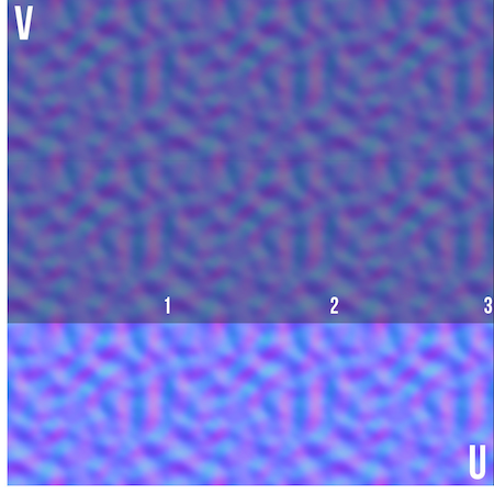
For example, here is the same texture tiled 2.2 times - a seam appeared immediately. For many, this is obvious, but it is important to understand why and how you should place your UV-scan in certain scenarios. We work with panning tiling textures, and besides, we do not need stitches, so we need to adapt the UV scan.

To make the picture more complete, look at the gif, where I move the UV map. In one, the width of the UV shell is exactly 1 (perfectly hidden), the other is trimmed so that the seam is visible. Since we only use tiling textures, the UV map does not have to be between 0 and 1.

At the waterfall (as with circles on the water) I also distorted the UV-map. Therefore, when using Panner, the texture moves faster or slower at certain points in the mesh. Additional polygons in this case make the transition between distorted areas less noticeable. Try turning on soft selection for UV curvature - this is how smooth transitions are made.

Notice how the texture is more stretched on the bend of the waterfall - this effect can be adjusted in different ways. Always imagine switching from UV to 3D. The closer the vertices of UV are to each other, the faster the texture will move along these UVs in 3D space when using Panner. If you move the UV vertices farther apart, the texture will appear more often on this area of the mesh and move more slowly in 3D space when using Panner. Experiment until you get the desired effect.
Note: This is a new material. Create a new material and apply a new shader on it (see part 1 ).
We again use one texture with multiple options for Panner speed / direction, as well as UV tiling (flip one of them, giving a negative U value). Add them on top of each other to get a more casual effect. And use their output to add many other settings: opacity, color variation and vertex displacement.

I also used scrolling normal maps. Only one, because it moves so fast with two Panner for variation, that in this case there will be no difference. Multiply it with a blue value of 1 (255 is indicated on the gif, this is when each channel has 256 steps, from 0 to 255), and also red and green values equal to 60 (or a value of 0.23 if you use the scale from 0 to 1). As a result, a too-saturated normal map became smoother and calmer. To return more intense normals, keep the R and G values the same and increase them. So you get a little more customization inside the shader itself.

We set up a mesh, UV, and other components that will be needed to make the waterfall work. Let's analyze a few things on this gif:

On it, the flow of water scrolls through the 3D mesh and is torn down. It can be seen that the type of transparent cut-out rendering is used here - the waterfall is completely opaque or completely transparent. Water changes color when it approaches the ground, and looks less smooth on white areas. Vertex displacement, about which we spoke earlier, is also noticeable. All these factors give the waterfall a more vibrant and natural look. Now more - let's start with color.
I use Lerp (linear interpolation) with two colors and a scrolling black and white texture, which was made at the beginning, as alpha (input signal). This texture basically serves as a mask to choose between showing blue or white. And Add connects to the vertex color node (node with vertex colors).

The following shows the vertex colors used. They work like vertex colors from the first part — that is, as a gradient. Colors are needed to make sure water gets whiter to the bottom of the waterfall. As we add vertex colors over the existing color (the whitest point is vertex color = 1), we can easily exceed the value 1. If this happens, we will get too bright and oversaturated results. Therefore, at the end there is a Clamp so that the maximum values do not exceed 1 (for a Clamp, the minimum = 0, and the maximum = 1). Using white and blue colors ensures that when water is “broken”, it will be in the white (foamed) area of the mesh and get a white border around transparent areas. The lighter the vertex color, the more vertices stick out. Thus, the end of the waterfall, which is brighter in vertex color, moves more chaotically. The bend of the waterfall is also a bit lighter - hence its speed.

Next, I made two additional meshes inside the main waterfall - so that a sense of volume appeared. The other two meshes are modified versions of the main mesh, with the same UV. They are slightly offset and modified so that the material looks different on all three meshes. This method does not take performance, but it helps a lot.
Additionally, we connect the fresnel in the emission channel to create a fake light that passes through the water. Fresnel makes a pixel as light as the normal vector on the surface of a 3D object is deflected from the camera and as dark as the normal vector is directed into the camera (perpendicular to the camera).
If you look at an angle, the waterfall becomes more “thin” - here fresnel comes in handy to show more fake light in these zones. In this case, it is impossible for the waterfall to glow - to reduce the effect, I used min node. Fresnel is often used with water shaders to change color depending on the viewing angle. Connecting 0 (black) to emission will not do anything, and connecting 1 (white) will make it an un-lit shader, which will look completely lit from all sides (even if it is in the shade).

To make it smooth, I flip vertex color using one minus node. If you scroll a little higher, you will see that the vertex color is light below and dark above. Turning them over (so that it becomes light above and dark below), you can make the lower part of the waterfall less smooth compared to the top. Darker values are less smooth surface, and lighter values - smoother.

Vertex displacement or vertex offset is an important thing to realize this effect. By shifting the peaks, the waterfall looks less static and therefore more alive.
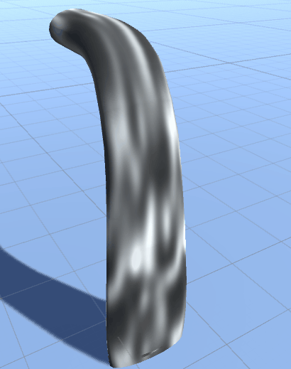
This is a waterfall without vertex displacement:

But with vertex displacement:
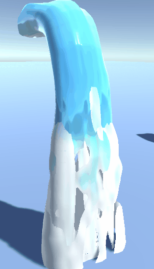
By moving the peaks based on our scrolling black and white texture, the waterfall becomes smoother. If you send the value 0.5 to the vertex offset output of the main node, nothing will happen. Try to keep gray with a value of 0.5 as the standard vertex value. Anything lower than 0.5 will move in a negative direction, and anything higher than 0.5 will move in a positive direction.
So how do we know in which direction the vertices will move? What is up and down?
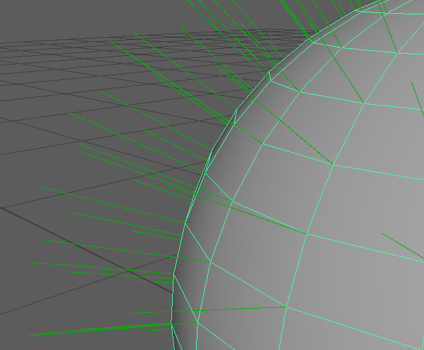
In our case, we want to move the vertices away from the surface of the mesh. A negative direction will mean that the vertex moves “inwards” relative to the direction of the vertex normal on the surface, and the positive direction will move “outwards”. For just such a vertex motion, we can use vertex normals. Each vertex, even if it is just one “point” in 3D space, has a direction assigned to it - vertex normal. It is used to calculate how the surface of the mesh should be shaded. In this example, I made a ball and asked in Maya the display of vertex normals (display> polygons> vertex normals). Each vertex has a direction, which by default indicates the distance from the surface. You can also edit any vertex normal and change its direction, but now the current suits us. Now you can use it in the shader and specify in which direction to move the vertices.
Vertex normal node displays RGB values that are based on the normal direction of the vertices of the mesh. In shaders and with normals in general, RGB values are used to express the 3D-object XYZ coordinates in 2D space. In order for our black and white Panner in the shader to move along the surface of a 3D object, we can use the RGB vertex normal values. I added vertex color to the vertices so that the bottom of the mesh becomes more convex. As well as several nodes to control the amount of displacement (this is normal if your values are below 0 or above 1).
For the demonstration I will give a sphere with vertex normal node, applied directly to the albedo (color) output of the main node.

The output of the RGB (XYZ) vertex normal node is based on the vertex normals of the mesh, which gives us this result.
Here is the complete node structure. It shows where and how everything connects.

I hope you have learned something new for yourself. My goal was to provide a sufficient amount of knowledge and starting points for creating such a waterfall on my own. To do such things, it is not necessary to know everything - enough basic things. Of course, I didn’t just open Amplify and create this effect in one fell swoop - there were other attempts that didn’t work.
Some more useful links on the topic:
Let's start with the obvious - take the usual Panner and mesh. You may be surprised: why so many polygons? Like in Simon's waterfall , I use vertex displacement to displace model vertices in 3D space through a shader. And to make it look beautiful, we need additional peaks. For optimization, you can create LOD meshes (Level Of Detail) with fewer polygons, and force Unity to switch to lower resolution models.
')
UV suture is located at the back. Even if the waterfall has no visible seams of texture, it is still better to hedge and place the UV seams in the least visible places for the player.
As in the case of mesh circles on the water, UV-scan should be with the least number of seams on the model when using tiling textures. One side of the UV shell is tied to 0 in the direction of U, and the other to 1. Remember that the width of the UV shell must fit into the integer value of the U-space (for example, tiling 1, 2 or 3). If we hitch 1.2 times in the direction of U, then a seam will appear at the junction. And we need a seamless tiling texture.
This is how a normal map looks tiled 3 times in a U-direction. Notice how the right side of the 3D image ideally falls in 1 in the U-direction. Setting the tiling to 3 in the U direction means that the texture repeats 3 times between 0 and 1 in the U direction (the image below shows the UV space from 0 to 1).
For example, here is the same texture tiled 2.2 times - a seam appeared immediately. For many, this is obvious, but it is important to understand why and how you should place your UV-scan in certain scenarios. We work with panning tiling textures, and besides, we do not need stitches, so we need to adapt the UV scan.
To make the picture more complete, look at the gif, where I move the UV map. In one, the width of the UV shell is exactly 1 (perfectly hidden), the other is trimmed so that the seam is visible. Since we only use tiling textures, the UV map does not have to be between 0 and 1.
At the waterfall (as with circles on the water) I also distorted the UV-map. Therefore, when using Panner, the texture moves faster or slower at certain points in the mesh. Additional polygons in this case make the transition between distorted areas less noticeable. Try turning on soft selection for UV curvature - this is how smooth transitions are made.
Notice how the texture is more stretched on the bend of the waterfall - this effect can be adjusted in different ways. Always imagine switching from UV to 3D. The closer the vertices of UV are to each other, the faster the texture will move along these UVs in 3D space when using Panner. If you move the UV vertices farther apart, the texture will appear more often on this area of the mesh and move more slowly in 3D space when using Panner. Experiment until you get the desired effect.
Note: This is a new material. Create a new material and apply a new shader on it (see part 1 ).
We again use one texture with multiple options for Panner speed / direction, as well as UV tiling (flip one of them, giving a negative U value). Add them on top of each other to get a more casual effect. And use their output to add many other settings: opacity, color variation and vertex displacement.
I also used scrolling normal maps. Only one, because it moves so fast with two Panner for variation, that in this case there will be no difference. Multiply it with a blue value of 1 (255 is indicated on the gif, this is when each channel has 256 steps, from 0 to 255), and also red and green values equal to 60 (or a value of 0.23 if you use the scale from 0 to 1). As a result, a too-saturated normal map became smoother and calmer. To return more intense normals, keep the R and G values the same and increase them. So you get a little more customization inside the shader itself.
We set up a mesh, UV, and other components that will be needed to make the waterfall work. Let's analyze a few things on this gif:
On it, the flow of water scrolls through the 3D mesh and is torn down. It can be seen that the type of transparent cut-out rendering is used here - the waterfall is completely opaque or completely transparent. Water changes color when it approaches the ground, and looks less smooth on white areas. Vertex displacement, about which we spoke earlier, is also noticeable. All these factors give the waterfall a more vibrant and natural look. Now more - let's start with color.
I use Lerp (linear interpolation) with two colors and a scrolling black and white texture, which was made at the beginning, as alpha (input signal). This texture basically serves as a mask to choose between showing blue or white. And Add connects to the vertex color node (node with vertex colors).
The following shows the vertex colors used. They work like vertex colors from the first part — that is, as a gradient. Colors are needed to make sure water gets whiter to the bottom of the waterfall. As we add vertex colors over the existing color (the whitest point is vertex color = 1), we can easily exceed the value 1. If this happens, we will get too bright and oversaturated results. Therefore, at the end there is a Clamp so that the maximum values do not exceed 1 (for a Clamp, the minimum = 0, and the maximum = 1). Using white and blue colors ensures that when water is “broken”, it will be in the white (foamed) area of the mesh and get a white border around transparent areas. The lighter the vertex color, the more vertices stick out. Thus, the end of the waterfall, which is brighter in vertex color, moves more chaotically. The bend of the waterfall is also a bit lighter - hence its speed.
Next, I made two additional meshes inside the main waterfall - so that a sense of volume appeared. The other two meshes are modified versions of the main mesh, with the same UV. They are slightly offset and modified so that the material looks different on all three meshes. This method does not take performance, but it helps a lot.
Additionally, we connect the fresnel in the emission channel to create a fake light that passes through the water. Fresnel makes a pixel as light as the normal vector on the surface of a 3D object is deflected from the camera and as dark as the normal vector is directed into the camera (perpendicular to the camera).
If you look at an angle, the waterfall becomes more “thin” - here fresnel comes in handy to show more fake light in these zones. In this case, it is impossible for the waterfall to glow - to reduce the effect, I used min node. Fresnel is often used with water shaders to change color depending on the viewing angle. Connecting 0 (black) to emission will not do anything, and connecting 1 (white) will make it an un-lit shader, which will look completely lit from all sides (even if it is in the shade).
To make it smooth, I flip vertex color using one minus node. If you scroll a little higher, you will see that the vertex color is light below and dark above. Turning them over (so that it becomes light above and dark below), you can make the lower part of the waterfall less smooth compared to the top. Darker values are less smooth surface, and lighter values - smoother.
Vertex displacement or vertex offset is an important thing to realize this effect. By shifting the peaks, the waterfall looks less static and therefore more alive.
This is a waterfall without vertex displacement:
But with vertex displacement:
By moving the peaks based on our scrolling black and white texture, the waterfall becomes smoother. If you send the value 0.5 to the vertex offset output of the main node, nothing will happen. Try to keep gray with a value of 0.5 as the standard vertex value. Anything lower than 0.5 will move in a negative direction, and anything higher than 0.5 will move in a positive direction.
So how do we know in which direction the vertices will move? What is up and down?
In our case, we want to move the vertices away from the surface of the mesh. A negative direction will mean that the vertex moves “inwards” relative to the direction of the vertex normal on the surface, and the positive direction will move “outwards”. For just such a vertex motion, we can use vertex normals. Each vertex, even if it is just one “point” in 3D space, has a direction assigned to it - vertex normal. It is used to calculate how the surface of the mesh should be shaded. In this example, I made a ball and asked in Maya the display of vertex normals (display> polygons> vertex normals). Each vertex has a direction, which by default indicates the distance from the surface. You can also edit any vertex normal and change its direction, but now the current suits us. Now you can use it in the shader and specify in which direction to move the vertices.
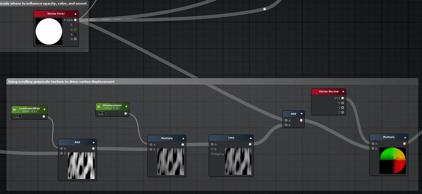
Vertex normal node displays RGB values that are based on the normal direction of the vertices of the mesh. In shaders and with normals in general, RGB values are used to express the 3D-object XYZ coordinates in 2D space. In order for our black and white Panner in the shader to move along the surface of a 3D object, we can use the RGB vertex normal values. I added vertex color to the vertices so that the bottom of the mesh becomes more convex. As well as several nodes to control the amount of displacement (this is normal if your values are below 0 or above 1).
For the demonstration I will give a sphere with vertex normal node, applied directly to the albedo (color) output of the main node.
The output of the RGB (XYZ) vertex normal node is based on the vertex normals of the mesh, which gives us this result.
Here is the complete node structure. It shows where and how everything connects.
I hope you have learned something new for yourself. My goal was to provide a sufficient amount of knowledge and starting points for creating such a waterfall on my own. To do such things, it is not necessary to know everything - enough basic things. Of course, I didn’t just open Amplify and create this effect in one fell swoop - there were other attempts that didn’t work.
Some more useful links on the topic:
- Report by Julian Love , who worked on Diablo as a VFX artist. Speech is mainly about skills in effects, but many of the things shown are applicable to other types of realtime VFX.
- Blog Little Chicken Game Company . He is dedicated to creating game art without textures and interesting techniques to create a beautiful environment.
- My mastermind Simon Trumpler has many other interesting things on the site. One of my favorites is the page with the so-called Game Art Tricks .
- YouTube channel with videos about shaders . My favorites are those in which they recreate specific effects from games (in Unity).
Source: https://habr.com/ru/post/442074/
All Articles