Thermal Acoustics Basics
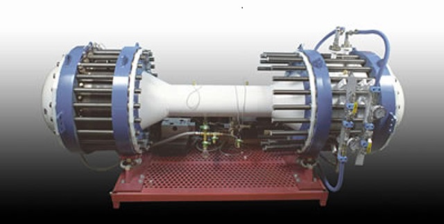
Fig. 1. Thermoacoustic refrigerator THEAC-25 with a traveling wave (on the left) and thermo-acoustic refrigerator with a standing wave Triton C-10c (on the right)
The previous parts are “1 article” , “2 article” .
')
1) Thermoacoustic motor, refrigerator and heat pump
1.1) Engine
In a thermoacoustic engine, thermal energy is converted into acoustic energy. Such a process is called a direct thermo-acoustic effect.
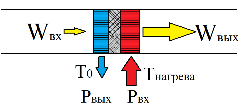
Fig. 2. Strengthening the power of the acoustic wave in the heat exchanger of the engine
At the entrance of the heat exchanger, a wave of small power, Win, enters and is amplified, passing through the engine heat exchanger to the value of Wout. In order to amplify the wave, it is necessary to expend thermal energy. Thermal energy P is supplied at heating temperature . Not all thermal energy can be converted into acoustic energy, since the maximum conversion efficiency of any heat engine is limited by the efficiency of the Carnot cycle. Therefore, one has to discharge part of the thermal power Pout into the environment. The temperature at which the heat is removed is - T. Please note that in the engine the direction of temperature rise in the heat exchanger and the direction in which the acoustic power grows coincide.
1.2) Refrigerator
The reverse thermoacoustic effect is realized in the refrigerator. That is, everything happens the other way around, compared to the engine. At the entrance of the heat exchanger of the refrigerator comes a powerful acoustic wave Win, which decays in the heat exchanger to the value of Wout. The loss of wave power is to create a temperature difference between the heat exchangers.
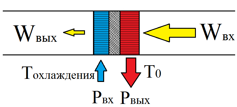
Fig. 3. Creating a temperature difference with wave attenuation
One of the heat exchangers begins to heat up, and the other begins to cool. That is, an acoustic wave takes heat from one heat exchanger and transfers it to another. In this case, the heating capacity Pout is to be discharged from the heating heat exchanger to the environment, and the heat output Pvc, which is the useful heat capacity of the refrigerator, enters the cold heat exchanger. Refrigerator cools any object to a temperature of Tochl.
1.3) Heat pump
A heat pump is essentially the same as a refrigerator, with the only difference that the thermal power taken from the environment is considered useful in a refrigerator, and the power given to the environment in a heat pump (for various needs).
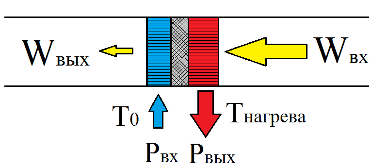
Fig. 4. Also creating a temperature difference when the wave decays, only the useful power is the heating power, not cooling
Note that in both the refrigerator and the heat pump the direction in which the temperature in the heat exchanger decreases is opposite to the direction in which the power of the acoustic wave decreases, which indicates that the reverse thermoacoustic effect is realized. An acoustic wave arriving at the input can be created using an engine, or using a powerful speaker or piston connected to a linear electric motor.
2) Devices with standing wave and devices with a traveling wave
According to the type of wave in the resonator, thermo-acoustic devices are divided into two types, devices with a traveling wave and devices with a standing wave.
Let's see what the differences between a traveling and a standing acoustic wave.
2.1) Running wave
Gifka 1. Graph of pressure, gas velocity and image of its displacement in a traveling wave
The traveling wave runs along the resonator on gif 1 to the right. In a traveling wave, gas pressure and velocity fluctuations are in phase. When this happens, energy is transferred in the direction of the wave motion. Pink ovals on hypha 1 depict diagrams of pressure as a function of the coordinates of elementary portions of gas at various points inside the resonator. The acoustic power carried by the wave to the right is numerically equal to the area of the pink oval, that is, the area of the PX diagram. As you can see, the ovals at different points are the same, which means that the wave power does not change when moving along the resonator. That is, the attenuation of the wave when moving along the resonator is not taken into account.
The traveling wave can propagate in a resonator, which is a looped tube. In this case, the wavelength corresponding to the resonant frequency of such a resonator will be equal to the length of the pipe itself.
Gifka. 2. The device with a traveling wave
2.2) Standing Wave
A standing wave is the sum of two traveling waves traveling in opposite directions. Such a wave can occur upon reflection, from any object and return to the sound source.
Gifka 3. Graph of pressure, gas velocity and image of its displacement in the standing wave
Gifka 3 depicts a standing wave in a half-wave resonator, that is, in a resonator with a length equal to half the wavelength. You can mentally imagine that the resonator on the bottom of the gif 3 is a pipe, muffled from both sides by plugs. In this case, someone, for example, shakes the pipe, and the gas inside dangles between the two ends of the pipe. Since the ends of the pipe are plugged, the gas velocity on the surface of the plugs can only be zero (as can be seen on the velocity graph). That is, at the ends of the pipe speed knots occur. At the same time, it is clear that pressure plugs (anti-nodes or pressure antinodes) will be the largest in amplitude on the plugs, and the pressure node (the point where there are no fluctuations) will be in the middle of the pipe.
In a standing wave, the phase difference between pressure fluctuations and speed fluctuations is 90 degrees. In this case, PX diagrams at all points of the resonator are lines, that is, figures that do not have an area. Accordingly, energy transfer in the standing wave does not occur, either to the right or to the left. But the wave itself naturally has energy.
A standing wave in a half-wave resonator can be created by placing a speaker or a piston at one of its ends, producing oscillations at the resonant frequency of the resonator. And by placing an additional heat exchanger in the resonator, it is possible to create a thermo-acoustic refrigerator.
Gifka 4. Standing wave in a half-wave resonator. On the left in the resonator there is a so-called stack - the analogue of the regenerator in a traveling-wave engine.
Due to the dissipation of acoustic energy in the resonator and in the heat exchanger, the resulting wave will not be purely standing. You will need a constant supply of energy from the piston. On gifka 4 it can be seen that, since the piston oscillates, then the gas at the piston oscillates with it. There is a transfer of acoustic energy from the piston to the resonator, which compensates for the loss of energy in the resonator. Thus, even though the resulting wave is very close to a standing wave, but on closer examination it is the sum of a standing and traveling wave.
In real thermo-acoustic devices, too, never purely traveling or purely standing wave. A wave is always something intermediate, but at the same time, if a wave in a device is very similar to a standing wave, then a device is called a standing wave device, and if a wave is similar to a traveling wave, then it is called a traveling wave device.
3) Main dimensions
3.1) Case length
The length of the housing - the resonator thermo-acoustic device is determined by the wavelength. It is even better to say on the contrary that the length of the resonator body determines the wavelength in the resonator.
In devices with a standing wave, the length of the body is usually equal to half the wavelength. For example, for a typical oscillation frequency of 300 Hz for this type of device, the length of the body when operating in air is about 0.56 meters, and when working on helium 1.65 meters.
Fig. 5. The main dimensions of the device with a standing wave
In devices with a traveling wave, the wavelength is approximately equal to the length of the body. The typical frequency of oscillations in such devices is 100 Hz, while the length of the body when operating in air will be 3.4 meters, and when working on helium - 10 meters.
Fig. 6. The main dimensions of the device with a traveling wave
3.2) Case diameter
The diameter of the case is determined based on the required power of the device. Power grows with an increase in the diameter of the device in proportion to the cross-sectional area of the case, as the power of the heat exchanger increases in proportion to the cross-sectional area.
The resonator is an ordinary pipe, preferably with smooth walls.
Gifka 5. The interaction of the oscillating gas with the wall of the resonator
If we consider the propagation of an acoustic wave in a cavity of a sufficiently large diameter (approximately one centimeter or more), it turns out that gas in a wave interacts with the wall of the resonator not in its entire volume, but only in a small boundary layer located near the wall of the resonator. It is shown on hypha 5 that with gas oscillations an unusual deformation of the gas velocity due to friction against the wall is formed near the wall of the resonator. The gas velocity on the wall surface is zero, which is usually accepted as a boundary condition in most hydrodynamic problems.
Viscous penetration depth
The vertical axis on the graph is marked in the so-called viscosity penetration δν.
The depth of viscous penetration is an estimate of the size of the layer that actively interacts with the wall of the body. For example, for an acoustic wave propagating in air with normal conditions, with a frequency of 70 Hz, the depth of viscous penetration is 0.27 mm. On hypha 5 it can be seen that the interaction between the wall and the gas is observed at values greater than the depth of viscous penetration, but, nevertheless, the region of sufficiently active interaction of the wave with the wall has a value of only about 1 mm. In the center of the resonator, the usual acoustic oscillations are observed, exactly the same as if there were no resonator at all. Accordingly, the scattering of acoustic energy due to friction against the walls occurs only in a narrow boundary layer near the wall.
Thermal penetration depth
In the acoustic wave, gas compression and expansion occur, and gas temperature fluctuates due to alternate adiabatic heating and cooling. This happens in a wave propagating in free space. When a wave moves in the resonator, the wave interacts with the wall of the resonator, and the wall temperature begins to influence the fluctuations of the gas temperature in the acoustic wave.
Just as for the viscous interaction with the wall, for thermal interaction there is also a quantity that characterizes the size of the gas layer that is actively thermally interacting with the wall. This value is called the thermal penetration depth δκ. Gas temperature fluctuations at the wall are deformed in the same way as the gas velocity in the previous example. So, if you simply say that now, not gas velocity but temperature fluctuations occur in GIFC 5 and that the vertical axis is now marked not in the depths of viscous penetration, but in the depths of the thermal one, then GIFC 5 will be true for temperature fluctuations. Numerically, the depth of thermal penetration is always greater than the depth of viscosity. For example, for the same air under normal conditions and at a frequency of 70 Hz, the depth of thermal penetration will be about 0.32 mm, which is only 1.185 times greater than the depth of viscosity in the previous example.
What conclusions can be drawn from all this?
Well, firstly, with a sufficiently large diameter of the resonator, the wave almost never viscous or thermally interacts with the resonator. The resonator only sets the direction of the wave and the type of wave. It follows that in order to transfer and take away thermal energy from a gas, the size of the channels (pores, holes, gaps) in the heat exchanger should be somewhere in the region of the thermal penetration, but in no case much more than this value.
Then, since the depths of viscous and thermal penetration are almost equal for any gases and for any frequencies, thermo-acoustic devices are doomed to have losses due to friction of the gas on the surface of the heat exchanger.
3.3) Dimensions of channels in the heat exchanger
For devices with a traveling wave, for maximum efficiency, the hydraulic radius of the pores in the heat exchanger must be less than the thermal penetration depth Rh <δk, in order to ensure good thermal contact between the gas and the surface of the heat exchanger. This condition follows from the equations of thermoacoustics. For a regenerator, this condition is especially important. Typically, the optimum hydraulic pore radius of the regenerator is somewhere between 3.5 and 6 times less than the depth of thermal penetration. The size of pores in heat exchangers affects the device much less than the size of pores in the regenerator; therefore, it is usually preferred to increase the sizes of pores (channels) in heat exchangers relative to the pores in the regenerator, for ease of manufacture.
The thermoacoustics equations on the other hand tell us that in devices with a standing wave, the value of the hydraulic pore radius of the stack (similar to the regenerator in devices with a traveling wave) should be approximately equal to the depth of thermal penetration in the gas. That is, in a device with a standing wave, the size of the pores in the stack should be somewhere 3.5-6 times larger than in a device with a traveling wave, all other things being equal. The size of the pores in the heat exchangers of devices with a standing wave does not so much affect the efficiency of the device as the size of the pores in the stack, as well as in devices with a traveling wave.
3.4) Length of heat exchangers and regenerator
In an acoustic wave, each elementary portion of the gas performs harmonic oscillations about its equilibrium position with amplitude X1 (see Fig. 5 and Fig. 6). The value of the optimal length of the regenerator or stack is usually greater than the magnitude of the gas displacement 2 | X1 | (more than twice the amplitude of the deviation of the elementary portion of gas from the equilibrium position). If the typical value for the offset value is 1 cm, then the regenerator or stack can be 1 cm to 5 cm long, depending on the operating temperature. The length of the heat exchangers has the same order as for the regenerator.
4) Thermodynamic cycle in devices with a standing wave and in devices with a traveling
4.1) Engine and standing wave cooler
The thermodynamic cycle realized in the device stack with a standing wave is closest to the Brighton cycle, which is realized in a gas turbine engine.
Engine
Gifka 6. Thermodynamic cycle in the engine with a standing wave
Gifka 6 shows the oscillations of the elementary volume of gas between the stack plates. Gas, making compression and expansion, changes its temperature (graph in the lower left corner). The plot of temperature versus coordinate is a figure resembling an oval (green line). The white line on the graph indicates the surface temperature of the stack. You can see that there is a temperature gradient along the length of the stack. That is, the temperature decreases linearly when moving from the left to the right end of the stack.
If the white line of the stack temperature has a slope on the graph more than the slope of the oval - the gas temperature graph, then the device works as an engine.
In the middle on the right is shown the PV diagram - the dependence of pressure on the volume in the elementary portion of the gas. The oval area in the diagram is numerically equal to the work done on gas in the case of an engine and the work done by gas in the case of a refrigerator (heat pump).
Since when working with a standing wave, the optimal size of the stack channels is approximately equal to the thermal penetration depth, the thermal contact of the gas and the solid surface is not perfect and the temperatures of the gas and the stack may differ from one another at a particular point in the stack. If the thermal contact between the gas and the stack were perfect, then the graphs of the temperature of the gas and the stack would coincide, since the gas would instantly take the temperature of the surface of the stack, no matter what point it is.
Critical temperature gradient in the stack
Gifka 7. Critical temperature gradient in the stack
Now we take the engine and begin to reduce the temperature difference on the stack, while somehow maintaining the amplitude of the acoustic wave, for example, using a speaker. If it is too late, a condition occurs in which the temperature in the elementary portion of the gas in the wave begins to fluctuate so that its temperature begins to coincide with the temperature of the stack surface, where this portion of the gas would be (hypha 7. green and white lines on the temperature graph match up).
In this case, no work is done on the stack (the PV diagram is a line — a figure with no area)
The temperature gradient in the stack, at which the case described above is realized, is called the critical temperature gradient for this particular wave. A device with a critical temperature gradient is absolutely useless for practical use. It occupies a position exactly between the engine and the refrigerator. Nevertheless, it is convenient to compare devices with respect to it, in order to find out whether this is the engine or the refrigerator.
Fridge
Gifka 8. Thermodynamic cycle in a standing wave fridge
If the temperature of the stack is less than the slope of the oval gas temperature, the device works as a refrigerator.
Please note that the rotation of the green point on the diagrams of the engine and the refrigerator go in opposite directions, which means that in one case work is done on gas, and in the other gas the work is done.
What needs to be done to turn the fridge into an engine? It is necessary either to increase the temperature gradient in the stack, while maintaining the amplitude of the acoustic wave, or to reduce the amplitude of the wave while maintaining the temperature gradient.
4.2) Engine and refrigerator with a traveling wave
The thermodynamic cycle realized in a regenerator of a device with a traveling wave is closest to the Stirling cycle, which is realized in the same engine.
In devices with a traveling wave, a case of ideal thermal contact between the gas and the surface of the regenerator is realized, thanks to the small optimal pore size.
Gifka 9. Thermodynamic cycle in a traveling-wave engine
Here, the gas temperature (the green line on the temperature graph) coincides with the temperature of the regenerator in all its points (the white line on the temperature graph). The PV diagram in the lower right corner indicates that gas is being worked on.
It should be understood that at least the temperature graphs of the gas and the regenerator coincide, but this is not a device with a critical temperature gradient, as previously described. In devices with a standing wave, it was necessary to select the necessary temperature gradient for this wave, so that it coincided with temperature fluctuations in the acoustic wave. In devices with a traveling wave, because the pores in the regenerator are very small, good thermal contact between the regenerator and the gas is always ensured. Therefore, the critical temperature gradient in devices with a traveling wave always exists and this term here loses any meaning. How, then, is work done on gas? After all, with a critical temperature gradient, in the case of a device with a standing wave, there was no work. The thing is that with a critical temperature gradient, it is not the work on the gas that is performed in the standing wave, and in the traveling wave another phase difference between the pressure and velocity fluctuations of the gas and the work in this case, on the contrary, is maximum.
For a traveling wave cooler, the graphs will look exactly the same as on gifka 9, except that the green dot on the PV diagram will rotate in the other direction, which will indicate that the gas is doing the work and not the gas is being done .
In conclusion, to everyone who wants to learn more about thermoacoustics, I would like to recommend the book by G. Swift, who made an enormous contribution to thermoacoustics, working at the Los Alamos National Laboratory:
Swift GW Thermoacoustic engines and refrigerators: a short course. Los Alamos: Los Alamos National Laboratory, 1999. 179 p. URL: download link
Also, I attach animations of thermo-acoustic processes created by the team of G. Swift:
download link . To view the animations, you need to unpack the archive, put it in the program files folder on your hard disk (otherwise, for some reason they do not work). All animations for windows are in the EXEs folder.
In this article, I retold only a small part of what is in this book, without using math. In the original, everything is much more interesting.
Source: https://habr.com/ru/post/441738/
All Articles