The math in Gamedev is simple. Curves and Ripples for the effect of rain in Unity
Hello! My name is Grisha, and I am the founder of CGDevs. We continue to talk about mathematics or something. Perhaps the main application of mathematics in game development and computer graphics in general is VFX. So let's talk about one such effect - rain, or rather, about its main part, which requires mathematics - ripples on the surface. We will consistently write a shader for ripples on the surface, and analyze its math. If interested - welcome under cat. Github project is attached.
Sometimes there comes a time in life when a programmer has to take up a tambourine and encourage rain. In general, the theme of rain modeling itself is very deep. There are many mathematical works on different parts of this process, from the fall of a drop and the effects associated with this to the distribution of drops in the volume. We analyze only one aspect - the shader, which will allow us to create an effect similar to a wave from a fallen drop. It's time to take up the tambourine!
Wave math
')
When searching the Internet you find a lot of funny mathematical expressions for generating ripples. Often they consist of some kind of "magic" numbers and a periodic function without justification. But in general, the math of this effect is quite simple.
We need only the equation of a plane wave in the one-dimensional case. Why we will analyze flat and one-dimensional later.
The equation of a plane wave in our case can be written as:
Aresult = A * cos (2 * PI * (x / waveLength - t * frequency));
Where:
Aresult - amplitude at point x, at time t
A - maximum amplitude
wavelength - wavelength
frequency - wave frequency
PI - number of PI = 3.14159 (float)
Shader
Let's play with shaders. The coordinate “-Z” will be responsible for the “top”. This is more convenient in the 2D case in Unity. If desired, the shader will not be difficult to rewrite to Y.
The first thing we need is the equation of a circle. The wave of our shader will be symmetrical about the center. The equation of a circle in the 2D case is described as:
r ^ 2 = x ^ 2 + y ^ 2
we need a radius, so the equation takes the form:
r = sqrt (x ^ 2 + y ^ 2)
and this will give us symmetry with respect to the point (0, 0) in the mesh, which will reduce everything to the one-dimensional case of a plane wave.
Now let's write a shader. I will not disassemble every step of writing a shader, since this is not the purpose of the article, but it is based on the Standard Surface Shader from Unity, the template of which can be obtained via Create-> Shader-> StandardSurfaceShader.
In addition, the properties necessary for the wave equation are added : _Frequency , _WaveLength and _WaveHeight . Property _Timer (it would be possible to use time with gpu, but during development and subsequent animation it is more convenient to control it manually.
Let's write the getHeight function to get the height (now it's the Z coordinate) by substituting the equation of a circle into the wave equation
Writing a shader with our wave equation and the equation of a circle, we get this effect.
Waves there. But I want the animation to begin and end with a plane. This will help us sine function. Multiplying the amplitude by sin (_Timer * PI) we obtain a smooth appearance and disappearance of waves. Since _Timer takes values from 0 to 1, and the sine at zero and in PI is zero, this is exactly what is needed.
While not at all like falling drops. The problem is that wave energy is lost evenly. Add the _Radius property, which will be responsible for the effect range. And multiply by the clamp amplitude (_Radius - rad, 0, 1) and we will get the effect more like the truth.
Well, the final step. The fact that the amplitude at each individual point reaches its maximum at the moment of time equal to 0.5 is not quite true, this function should be replaced.

Then I felt a little lazy to count, and I simply multiplied the sine by (1 - _Timer) and got such a curve.
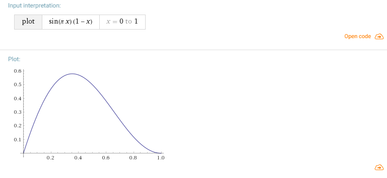
But in general, from the point of view of mathematics, it is also possible to choose the desired curve based on the logic at which point in time you want the peak and the approximate form, and then build an interpolation on these points.
The result was such a shader and effect.
Mesh mesh is important
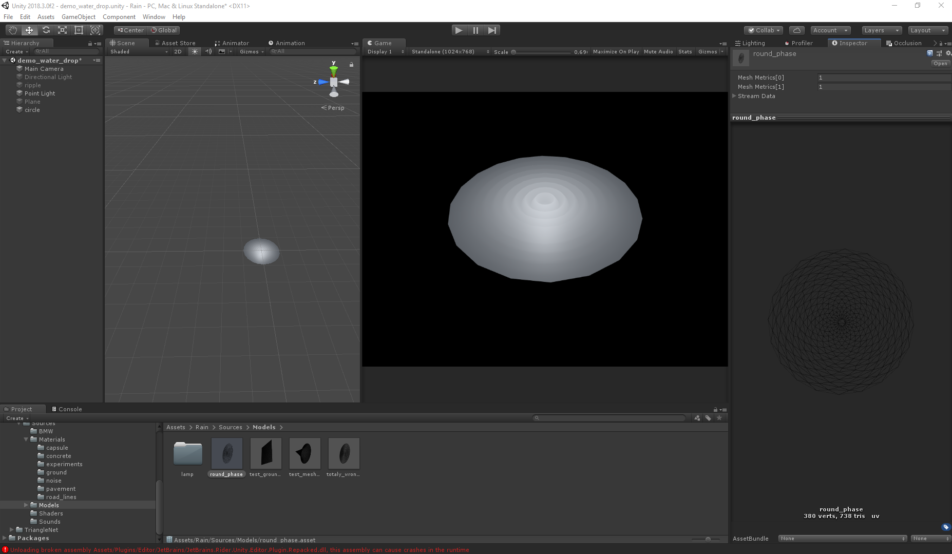
Returning a little to the topic of the previous article . The waves are implemented by a vertex shader, so the mesh of the mesh plays a fairly large role. Since the nature of the movement is known, the task is simplified, but in general the final visual depends on the shape of the grid. The difference is not significant at high polygonality, but for productivity, the smaller the polygons, the better. Below are pictures illustrating the difference between grids and visuals.
Right:
Wrong:
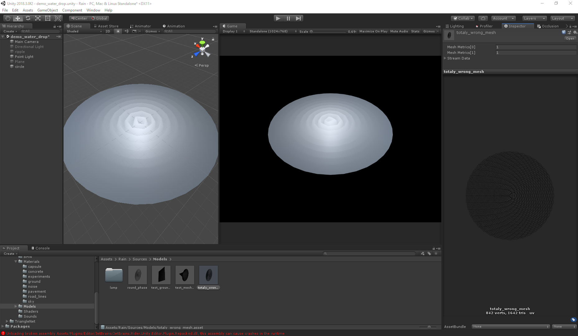
Even with twice the number of polygons, the second mesh gives the wrong visual (both meshes are generated using Triangle.Net, just for different algorithms).
Final visual
A special part has been added to another version of the shader to create waves not strictly in the center, but at several points. How this is implemented and how you can pass on such parameters I can tell in the next articles if the topic is interesting.
Here is the shader itself:
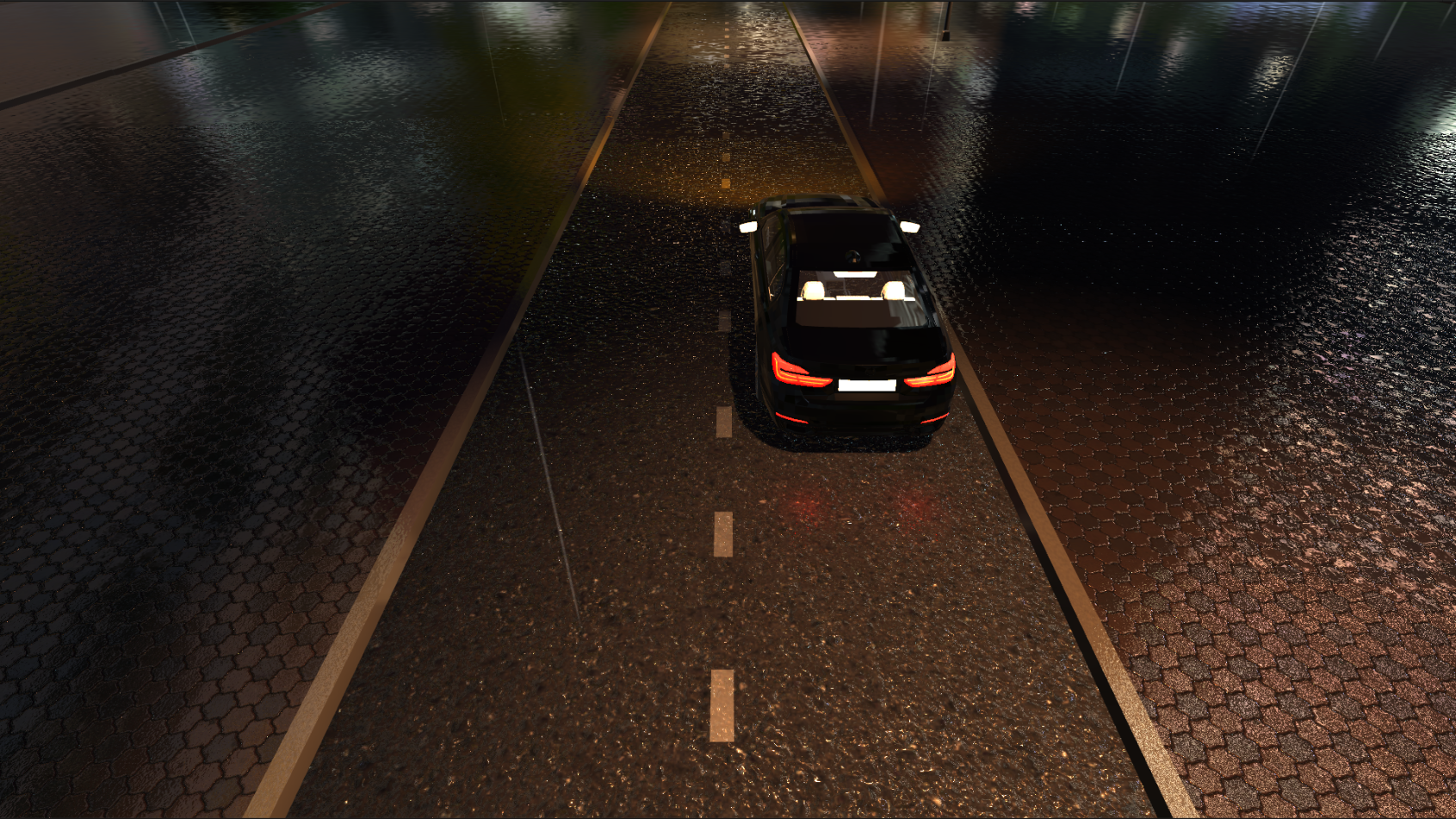
The project as a whole and how it works can be found here . True, some of the resources had to be removed due to the weight restrictions of the githab (hdr skybox and machine).
Thanks for attention! I hope the article will be useful to someone, and it became a little clearer why you might need trigonometry, analytical geometry (everything related to curves) and other mathematical disciplines.
Sometimes there comes a time in life when a programmer has to take up a tambourine and encourage rain. In general, the theme of rain modeling itself is very deep. There are many mathematical works on different parts of this process, from the fall of a drop and the effects associated with this to the distribution of drops in the volume. We analyze only one aspect - the shader, which will allow us to create an effect similar to a wave from a fallen drop. It's time to take up the tambourine!
Wave math
')
When searching the Internet you find a lot of funny mathematical expressions for generating ripples. Often they consist of some kind of "magic" numbers and a periodic function without justification. But in general, the math of this effect is quite simple.
We need only the equation of a plane wave in the one-dimensional case. Why we will analyze flat and one-dimensional later.
The equation of a plane wave in our case can be written as:
Aresult = A * cos (2 * PI * (x / waveLength - t * frequency));
Where:
Aresult - amplitude at point x, at time t
A - maximum amplitude
wavelength - wavelength
frequency - wave frequency
PI - number of PI = 3.14159 (float)
Shader
Let's play with shaders. The coordinate “-Z” will be responsible for the “top”. This is more convenient in the 2D case in Unity. If desired, the shader will not be difficult to rewrite to Y.
The first thing we need is the equation of a circle. The wave of our shader will be symmetrical about the center. The equation of a circle in the 2D case is described as:
r ^ 2 = x ^ 2 + y ^ 2
we need a radius, so the equation takes the form:
r = sqrt (x ^ 2 + y ^ 2)
and this will give us symmetry with respect to the point (0, 0) in the mesh, which will reduce everything to the one-dimensional case of a plane wave.
Now let's write a shader. I will not disassemble every step of writing a shader, since this is not the purpose of the article, but it is based on the Standard Surface Shader from Unity, the template of which can be obtained via Create-> Shader-> StandardSurfaceShader.
In addition, the properties necessary for the wave equation are added : _Frequency , _WaveLength and _WaveHeight . Property _Timer (it would be possible to use time with gpu, but during development and subsequent animation it is more convenient to control it manually.
Let's write the getHeight function to get the height (now it's the Z coordinate) by substituting the equation of a circle into the wave equation
Writing a shader with our wave equation and the equation of a circle, we get this effect.
Shader code
Shader "CGDevs/Rain/RainRipple" { Properties { _WaveHeight("Wave Height", float) = 1 _WaveLength("Wave Length", float) = 1 _Frequency("Frequency", float) = 1 _Timer("Timer", Range(0,1)) = 0 _Color ("Color", Color) = (1,1,1,1) _MainTex ("Albedo (RGB)", 2D) = "white" {} _Glossiness ("Smoothness", Range(0,1)) = 0 _Metallic ("Metallic", Range(0,1)) = 0.0 } SubShader { Tags { "RenderType"= "Opaque" } LOD 200 CGPROGRAM #pragma surface surf Standard fullforwardshadows vertex:vert #pragma target 3.0 sampler2D _MainTex; struct Input { float2 uv_MainTex; }; half _Glossiness, _Metallic, _Frequency, _Timer, _WaveLength, _WaveHeight; fixed4 _Color; half getHeight(half x, half y) { const float PI = 3.14159; half rad = sqrt(x * x + y * y); half wavefunc = _WaveHeight * cos(2 * PI * (_Frequency * _Timer - rad / _WaveLength)); return wavefunc; } void vert (inout appdata_full v) { v.vertex.z -= getHeight(v.vertex.x, v.vertex.y); } void surf (Input IN, inout SurfaceOutputStandard o) { fixed4 c = tex2D (_MainTex, IN.uv_MainTex) * _Color; o.Albedo = c.rgb; o.Metallic = _Metallic; o.Smoothness = _Glossiness; o.Alpha = _Color.a; } ENDCG } FallBack "Diffuse" } Waves there. But I want the animation to begin and end with a plane. This will help us sine function. Multiplying the amplitude by sin (_Timer * PI) we obtain a smooth appearance and disappearance of waves. Since _Timer takes values from 0 to 1, and the sine at zero and in PI is zero, this is exactly what is needed.
While not at all like falling drops. The problem is that wave energy is lost evenly. Add the _Radius property, which will be responsible for the effect range. And multiply by the clamp amplitude (_Radius - rad, 0, 1) and we will get the effect more like the truth.
Well, the final step. The fact that the amplitude at each individual point reaches its maximum at the moment of time equal to 0.5 is not quite true, this function should be replaced.
Then I felt a little lazy to count, and I simply multiplied the sine by (1 - _Timer) and got such a curve.
But in general, from the point of view of mathematics, it is also possible to choose the desired curve based on the logic at which point in time you want the peak and the approximate form, and then build an interpolation on these points.
The result was such a shader and effect.
Shader code
Shader "CGDevs/Rain/RainRipple" { Properties { _WaveHeight("Wave Height", float) = 1 _WaveLength("Wave Length", float) = 1 _Frequency("Frequency", float) = 1 _Radius("Radius", float) = 1 _Timer("Timer", Range(0,1)) = 0 _Color ("Color", Color) = (1,1,1,1) _MainTex ("Albedo (RGB)", 2D) = "white" {} _Glossiness ("Smoothness", Range(0,1)) = 0 _Metallic ("Metallic", Range(0,1)) = 0.0 } SubShader { Tags { "RenderType"= "Opaque" } LOD 200 CGPROGRAM #pragma surface surf Standard fullforwardshadows vertex:vert #pragma target 3.0 sampler2D _MainTex; struct Input { float2 uv_MainTex; }; half _Glossiness, _Metallic, _Frequency, _Timer, _WaveLength, _WaveHeight, _Radius; fixed4 _Color; half getHeight(half x, half y) { const float PI = 3.14159; half rad = sqrt(x * x + y * y); half wavefunc = _WaveHeight * sin(_Timer * PI) * (1 - _Timer) * clamp(_Radius - rad, 0, 1) * cos(2 * PI * (_Frequency * _Timer - rad / _WaveLength)); return wavefunc; } void vert (inout appdata_full v) { v.vertex.z -= getHeight(v.vertex.x, v.vertex.y); } void surf (Input IN, inout SurfaceOutputStandard o) { fixed4 c = tex2D (_MainTex, IN.uv_MainTex) * _Color; o.Albedo = c.rgb; o.Metallic = _Metallic; o.Smoothness = _Glossiness; o.Alpha = _Color.a; } ENDCG } FallBack "Diffuse" } Mesh mesh is important
Returning a little to the topic of the previous article . The waves are implemented by a vertex shader, so the mesh of the mesh plays a fairly large role. Since the nature of the movement is known, the task is simplified, but in general the final visual depends on the shape of the grid. The difference is not significant at high polygonality, but for productivity, the smaller the polygons, the better. Below are pictures illustrating the difference between grids and visuals.
Right:
Wrong:
Even with twice the number of polygons, the second mesh gives the wrong visual (both meshes are generated using Triangle.Net, just for different algorithms).
Final visual
A special part has been added to another version of the shader to create waves not strictly in the center, but at several points. How this is implemented and how you can pass on such parameters I can tell in the next articles if the topic is interesting.
Here is the shader itself:
Ripple Vertex with Pole
Shader "CGDevs/Rain/Ripple Vertex with Pole" { Properties { _MainTex ("Albedo (RGB)", 2D) = "white" {} _Normal ("Bump Map", 2D) = "white" {} _Roughness ("Metallic", 2D) = "white" {} _Occlusion ("Occlusion", 2D) = "white" {} _PoleTexture("PoleTexture", 2D) = "white" {} _Color ("Color", Color) = (1,1,1,1) _Glossiness ("Smoothness", Range(0,1)) = 0 _WaveMaxHeight("Wave Max Height", float) = 1 _WaveMaxLength("Wave Length", float) = 1 _Frequency("Frequency", float) = 1 _Timer("Timer", Range(0,1)) = 0 } SubShader { Tags { "IgnoreProjector" = "True" "RenderType" = "Opaque"} LOD 200 CGPROGRAM #pragma surface surf Standard fullforwardshadows vertex:vert #pragma target 3.0 sampler2D _PoleTexture, _MainTex, _Normal, _Roughness, _Occlusion; half _Glossiness, _WaveMaxHeight, _Frequency, _Timer, _WaveMaxLength, _RefractionK; fixed4 _Color; struct Input { float2 uv_MainTex; }; half getHeight(half x, half y, half offetX, half offetY, half radius, half phase) { const float PI = 3.14159; half timer = _Timer + phase; half rad = sqrt((x - offetX) * (x - offetX) + (y - offetY) * (y - offetY)); half A = _WaveMaxHeight * sin(_Timer * PI) * (1 - _Timer) * (1 - timer) * radius; half wavefunc = cos(2 * PI * (_Frequency * timer - rad / _WaveMaxLength)); return A * wavefunc; } void vert (inout appdata_full v) { float4 poleParams = tex2Dlod (_PoleTexture, float4(v.texcoord.xy, 0, 0)); v.vertex.z += getHeight(v.vertex.x, v.vertex.y, (poleParams.r - 0.5) * 2, (poleParams.g - 0.5) * 2, poleParams.b , poleParams.a); } void surf (Input IN, inout SurfaceOutputStandard o) { o.Albedo = tex2D(_MainTex, IN.uv_MainTex).rgb * _Color.rgb; o.Normal = UnpackNormal(tex2D(_Normal, IN.uv_MainTex)); o.Metallic = tex2D(_Roughness, IN.uv_MainTex).rgb; o.Occlusion = tex2D(_Occlusion, IN.uv_MainTex).rgb; o.Smoothness = _Glossiness; o.Alpha = _Color.a; } ENDCG } FallBack "Diffuse" } The project as a whole and how it works can be found here . True, some of the resources had to be removed due to the weight restrictions of the githab (hdr skybox and machine).
Thanks for attention! I hope the article will be useful to someone, and it became a little clearer why you might need trigonometry, analytical geometry (everything related to curves) and other mathematical disciplines.
Source: https://habr.com/ru/post/435828/
All Articles