How to work with Shader Graph in Unity3D
Shader graphs are a new tool for creating shaders in a unit. It allows you to create shaders for people who do not have the skills to write code. The result of each operation is visible when editing. The ideal tool for beginners and experimenters.
Adding a Shader Graph to a project is done using the Package Manager.
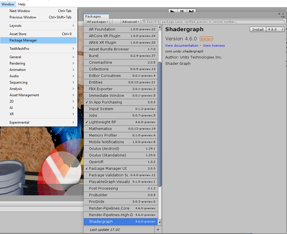
')
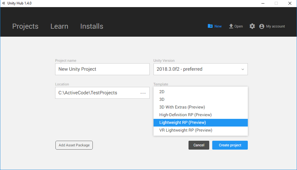
But for today the version is available only for Lightweight Render Pipeline, so for experiments you need to create a project like this:
Simplest shader
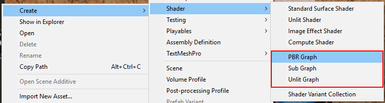
Shader Graph allows you to create two types of shaders Unlit (without lighting) and PBR (photo-realistic render), as well as sub (node for the shader). The latter can be used inside Unlit and PBR shaders.
Unlit does not use the built-in features in the unit for lighting and shading the model, only displays the texture on top of the model and therefore it is much easier to get acquainted with it.
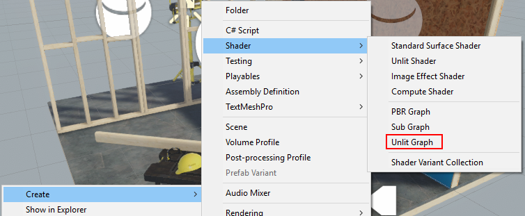
Create material and create Unlit Graph. By dragging, assign a shader to the material.
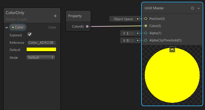
Opening the shader with a double click we will see the master node
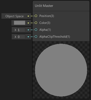
At the output of this shader, we can control:
- Position - vertex position
- Color - the color of each pixel of the surface
- Alpha - its transparency
- AlphaClipThreshold - transparency threshold, if we do not use translucency
The vast majority of shaders do not use translucency due to computational complexity and limitations imposed on such shaders. And where you can do without translucency, you have to do without it.
Whether your shader will use translucency or not, you can configure it in the master node:
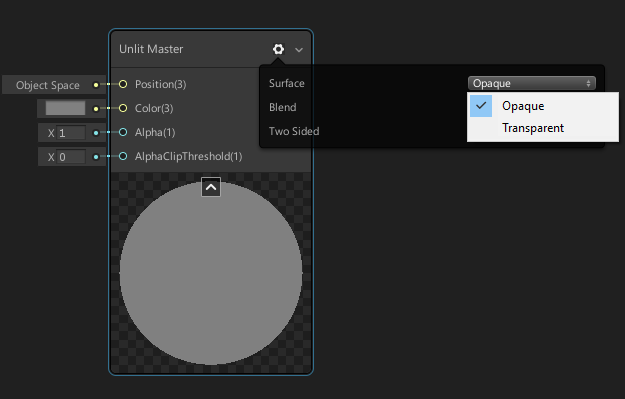
- Opaque - opaque
- Transparent - translucent
To color the model, we can apply a three-dimensional vector or color to the input (color) of the master node, which is essentially the same for the shader, only displayed differently in the graph.
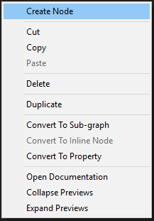
New nodes are created via the context menu.
in this case, we can use two Color nodes or Vector4

but so that they can be customized from the inspector we need to create a property

and then drag it to the graph with the mouse, thereby creating a node.

- Exposed - allows you to see this property in the inspector when editing material
- Default - sets the default color value
- Mode - allows you to select the brightness range (HDR allows you to go beyond the normal brightness)
In order for the created property to affect the color of the material, its output must be connected to the Color input at the master node.
The same shader, but the code
Shader "Tutorial/Simpliest" // Shader - , // // url- { Properties // , // inspector Unity { _Color ("Color", Color) = (0.5,0.6,0.7,1) // : // _Color - , // CGPROGRAM // "Color" - , // Inspector // Color - , // Inspector, // 5 : // Color - , // Vector - 4 , // Float - , // 2D - , // CUBE - // (0.5,0.6,0.7,1) - } SubShader // , // { // No culling or depth // , // GPU, // , ZTest Always // , Cull Off ZWrite Off ZTest Always Pass // SubShader, // Pass // , Pass { CGPROGRAM // , // #pragma vertex vert_img // // vert_img, #pragma fragment frag // // frag, #include "UnityCG.cginc" // , // Unity // vert_img, // : // %UNITY%\Editor\Data\CGIncludes\UnityCG.cginc fixed4 _Color; // fixed4 - , // 4 fixed fixed4 frag (v2f_img i) : COLOR { fixed4 col = _Color; return col; } ENDCG // , } } } The easiest shader with texture
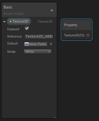
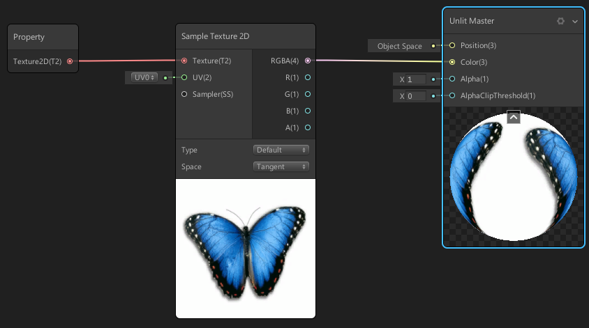
To put our texture on the mesh, we need to create a node that can be configured from the outside by the Shader Graph. To do this, create a property
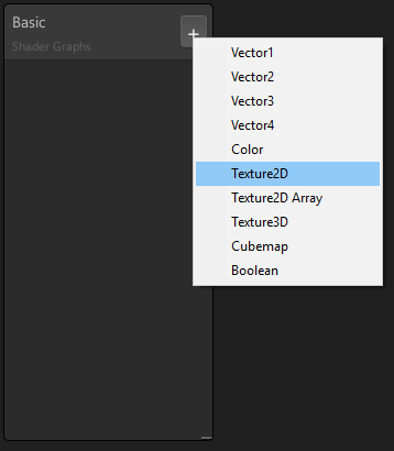
and stretch it out, creating a texture node
After that, you need to create a texture sampler node that can receive a texture and uv-coordinate as an input, and give a pixel color as an output.
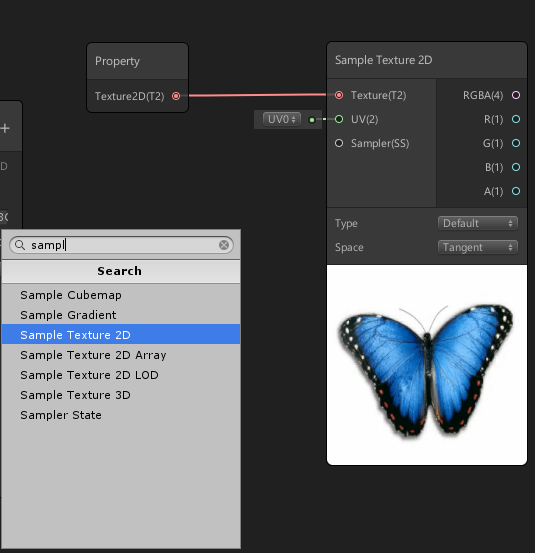
The sampler output is connected to the master color node's input.
Simplest shader with texture code
Shader "Tutorial/Texture" { Properties { _MainTex("Texture", 2D) = "white" {} // , // , Inspector // . "white" , // , . } SubShader { Cull Off ZWrite Off ZTest Always Pass { CGPROGRAM #pragma vertex vert_img #pragma fragment frag #include "UnityCG.cginc" sampler2D _MainTex; // sampler2D - // , , // _MainTex Properties, // . fixed4 frag(v2f_img i) : COLOR { // // , , // , // . // tex2D - , // (_MainTex) // , (i.uv) UV // . fixed4 col = tex2D(_MainTex, i.uv); return col; } ENDCG } } } Negative texture
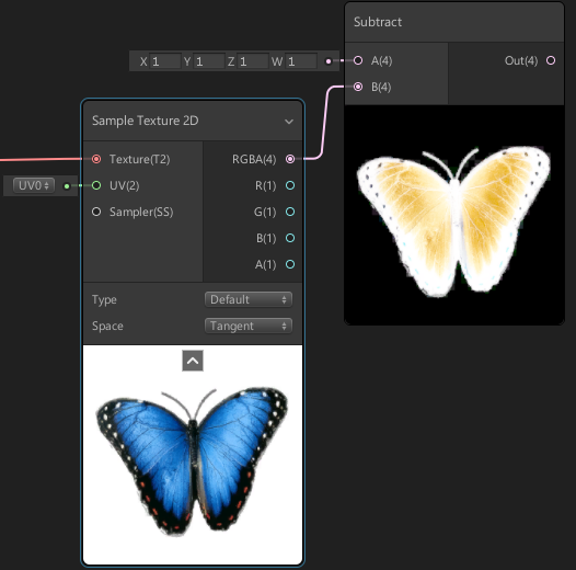
Before displaying the texture on the screen, we can change it by applying mathematical operations. For example, create a negative by simple subtraction.
Add a substract subtract that will be reduced (1; 1; 1; 1), and the texture subtracted by the output.
Negative texture code
Shader "Tutorial/Texture" { Properties { _MainTex("Texture", 2D) = "white" {} } SubShader { Cull Off ZWrite Off ZTest Always Pass { CGPROGRAM #pragma vertex vert_img #pragma fragment frag #include "UnityCG.cginc" sampler2D _MainTex; fixed4 frag(v2f_img i) : COLOR { fixed4 col = tex2D(_MainTex, i.uv); col = 1 - col; // , 4- // RedGreenBlueAlpha - , // 0 1 return col; } ENDCG } } } Mixing two textures
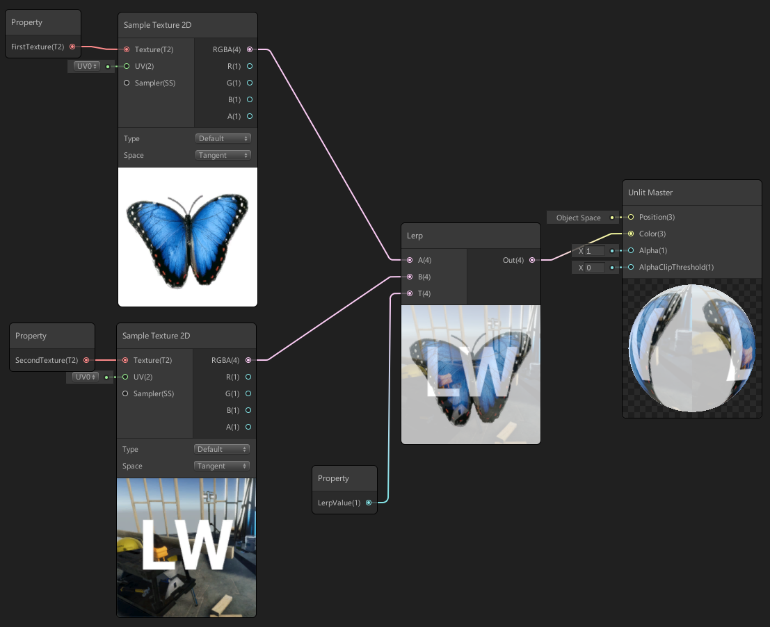
In order to mix two textures, we need three properties, two of which will be textures, and the third number, which will indicate to what extent they should be mixed.
And the blending operation itself will produce a Lerp node.
Mixing two textures by code
Shader "Tutorial/NoiseOverlay" { Properties { _MainTex("Main Texture", 2D) = "white" {} _NoiseTex("Noise Texture", 2D) = "white" {} _LerpValue("Lerp Value", Range(0, 1)) = 0.5 } SubShader { Cull Off ZWrite Off ZTest Always Pass { CGPROGRAM #pragma vertex vert_img #pragma fragment frag #include "UnityCG.cginc" sampler2D _MainTex; sampler2D _NoiseTex; float _LerpValue; fixed4 frag(v2f_img i) : COLOR { half4 base = tex2D(_MainTex, i.uv); half4 overlay = tex2D(_NoiseTex, i.uv); return lerp(base, overlay , _LerpValue); } ENDCG } } } Cutout mask
To make a part of the model completely transparent, input the Alpha channel value to the master node input, create a slider property and submit it to the AlphaClipThreshold input
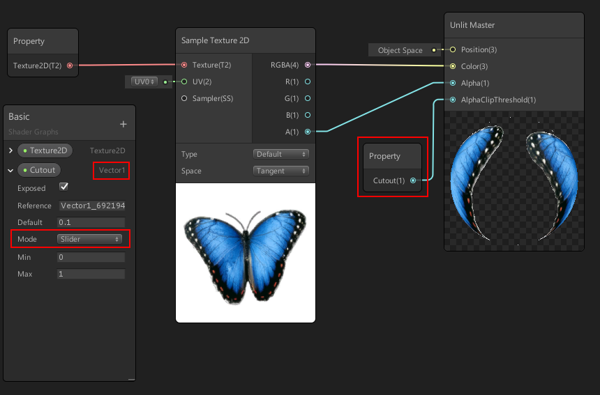
The slider is needed to fix the bug in the Graph shader, which does not allow cutout and besides, it will allow you to change the value of the material settings.
UV inversion
To work with UV, you need to create a UV node and connect it to the texture sampler.
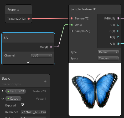
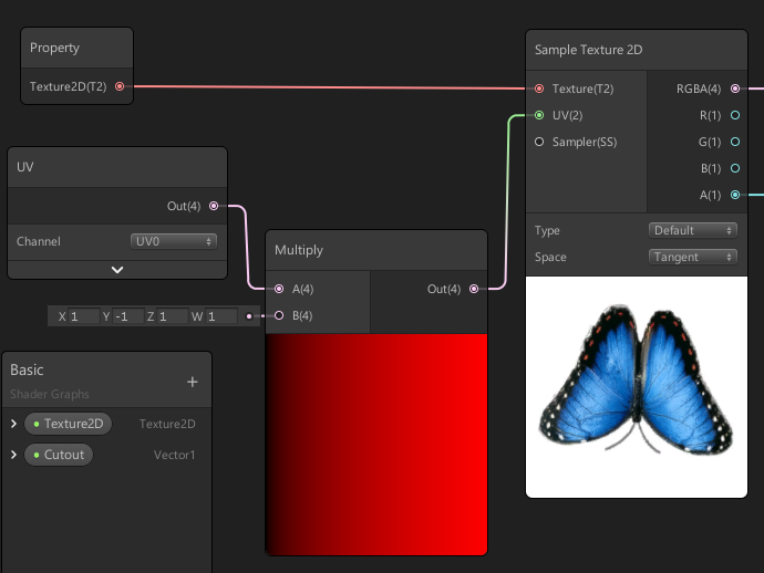
here you can select the UV channel, some models of these channels may have several, in the case of multi-layered textures. With this step, we didn’t change anything, but to invert UV, we need to create a node that inverts UV values, the usual multiplication by -1 Y coordinates will suit us.
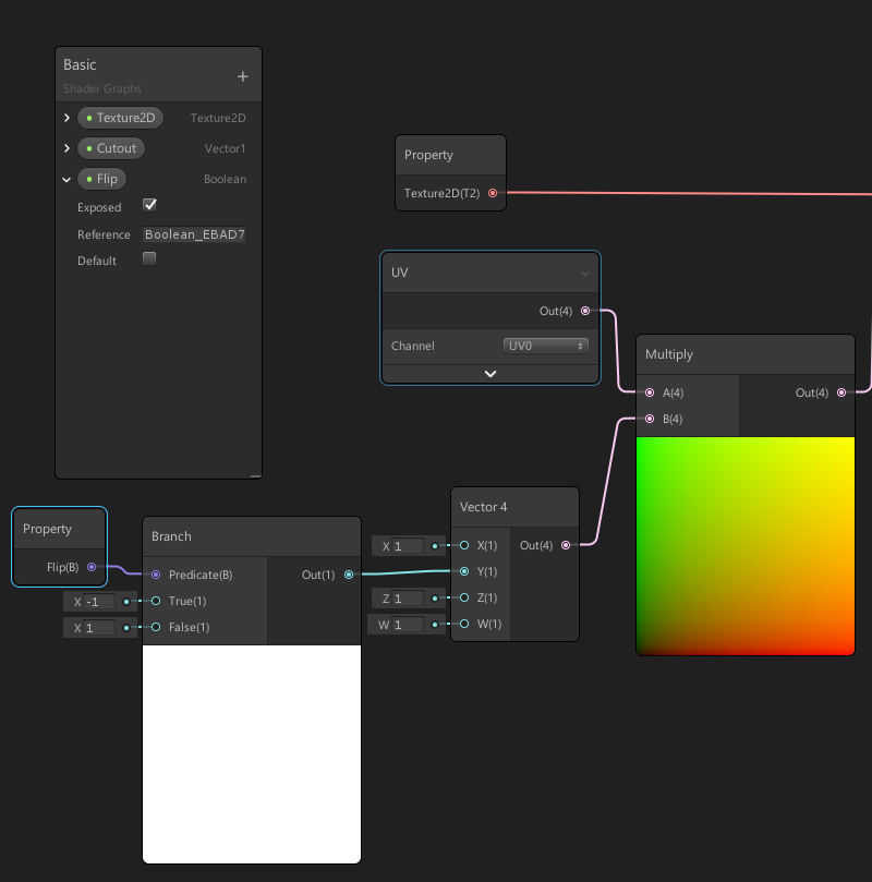
Mirroring the texture can be made custom from the material, for this we need the Branch node, it gets a boolean value for input, and one of two values for output, in our case 1 or -1
Impressions
Creating a shader with Shader Graph greatly simplifies the task, if only because you can observe the change in the result after each step of the computation. The principle of creation through the editor node allows you to create something new even to those who do not understand anything in shaders. The tool is still raw, but already very useful. Since you can experiment in the editor, and then reproduce the code, the names of the functions in most cases coincide with the name of the nodes, so the Shader Graph can be useful to programmers.
PS thank Darkirius for help in preparing the article
PPS you can also get acquainted with the lessons on writing shaders in a unit by the link Hit-book
Source: https://habr.com/ru/post/435328/
All Articles