ITER Project in 2018
Project
The past year for the ITER International Thermonuclear Experimental Reactor ( about the project ) has become, for an external observer, probably one of the quietest in all the years of construction (since 2009). For me personally, this year was marked by a visit to the ITER site in September 2018, so this annual report will be diluted with personal impressions and photos.
Three years ago, the project officially changed its director - he became an energetic Frenchman Bernard Bigot. Aware of the difficult situation in which ITER was at the beginning of his rule (the growing enormous backlog of schedule and cost overruns raised the question of closure), Bigo undertook several important management decisions, including the creation of a “comprehensive construction plan”. As you know, graphs of this scale are precisely observed only at the time of creation / update, and over the past 2 years it can be stated that 100% of the following is not even a new schedule. However, the situation is clearly better than it was in the period 2009–2015, and the lag today is 6-9 months, especially since there are options for “sealing” the plans for the assembly of the reactor. The value within the year is not too critical for such a project, the question is basically - what will happen with the lag behind?
Unfortunately, it seems to me - the backlog will increase. One of the remaining problems is the underfinancing by the Americans of their part of the program. Although the scale of this underfunding was reduced by half in 2018, it still remains and means a breakdown in the supply of critical pieces of equipment that the United States pays. For example, the water cooling system of the vacuum chamber and the divertor was eventually transferred to the development and production from the US to the European Union in an attempt to save money and time. But, obviously, the timing of this system will still slip.
')
The situation with American financing reflects well the general problem - in a supranational project, national ambitions clash, multiplied by the ambitions of specific people involved in the project, which makes the work of development engineers (and so technically extremely complicated) more complicated.
Closing this “social” moment, I just want to note that humanity, the farther away, the more it will encounter large-scale international projects and learn to implement them. Thus, the negative experience of ITER and the solutions that allow this negative to overcome are valuable in their own right. For example, if humanity takes seriously the “emergency” reduction of CO2 emissions - ITER with its “social” experience here can bring more benefits than with energy.
However, back to the project. The year 2018, on its own, as a whole, passed in a forward movement - many new equipment of a thermonuclear facility was created, important stands were earned, important scientific results were obtained. In 2019, it is expected to mark “70% of the work performed on the construction of buildings”. Let's dive into the details.
Construction and installation of equipment
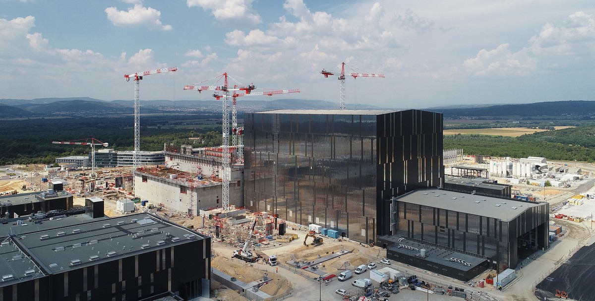
- The main news of 2018 - the construction of the starting minimum is almost completed. If last year I wrote about new ready-made buildings, then in 2018 there were none, just the completion. However, there is still a full cycle of construction ahead of 4 facilities - the building management complex, the building with the resistors of magnetic energy and two emergency diesel generator sets.

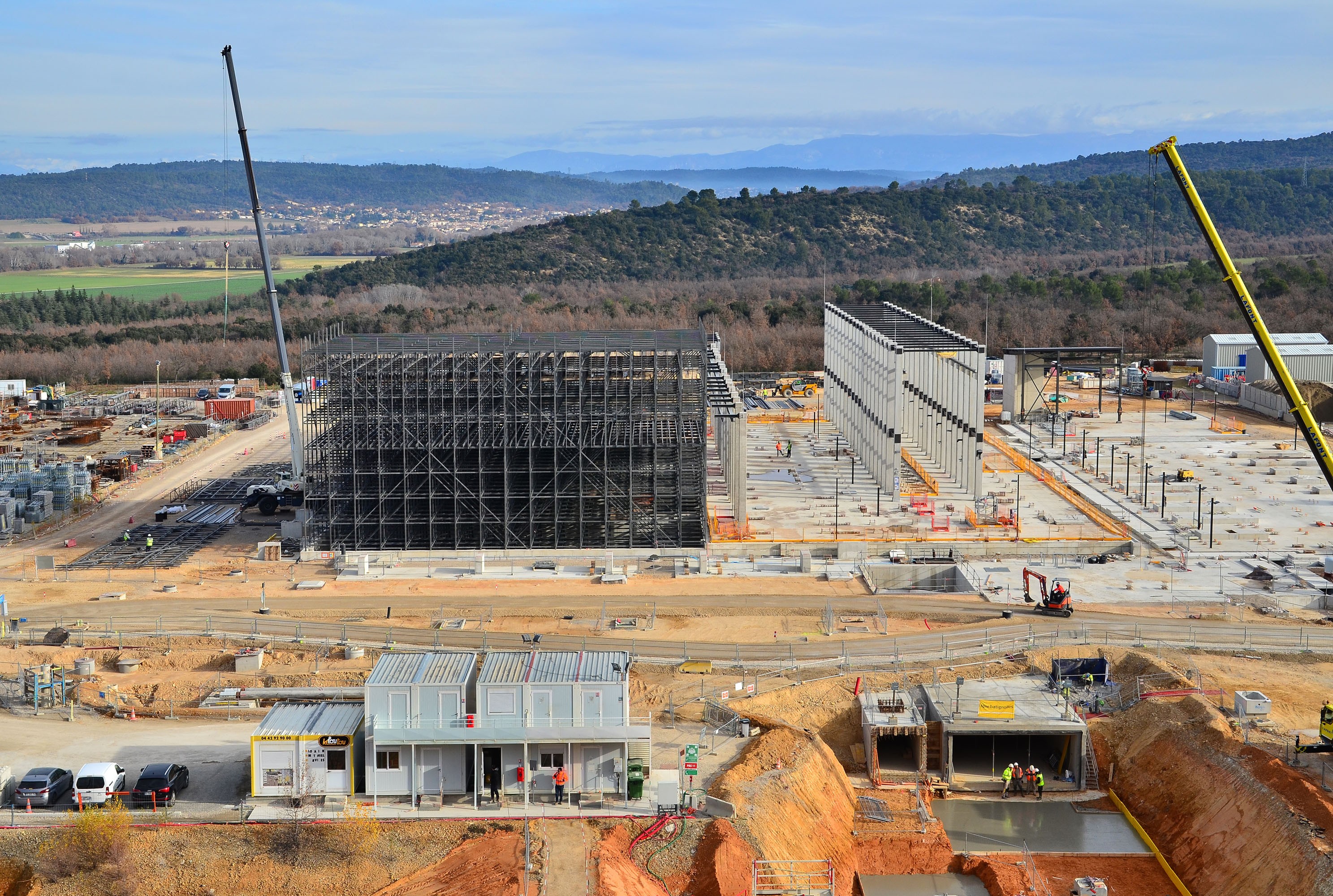
- For 2018, the most complex structure - the complex building of a tokamak grew by ten meters and practically reached the top of concrete structures, over which, however, still has to be erected a roof of metal structures. Formally, builders have about a year to complete the concrete, build a roof, disassemble the intermediate wall between the pre-assembly building and the reactor shaft, and finally start assembling the reactor.
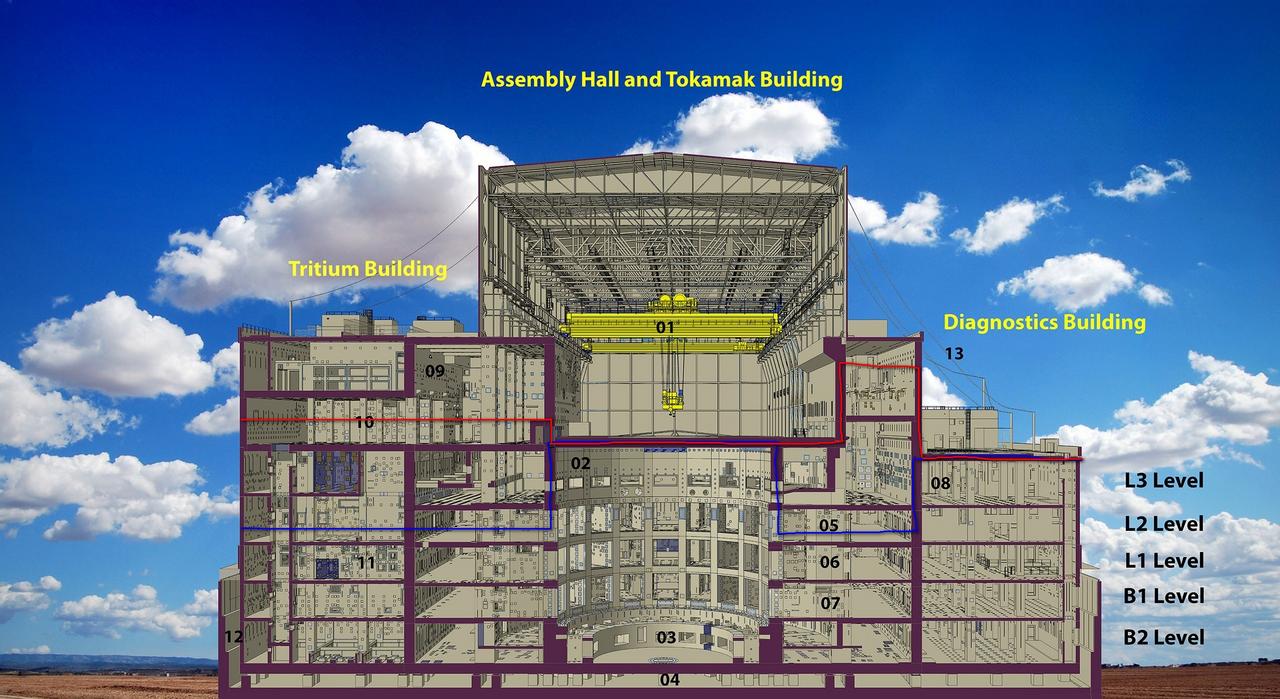
Progress in the construction of the main building in 2018 - between the blue and red lines. Left just a little bit.
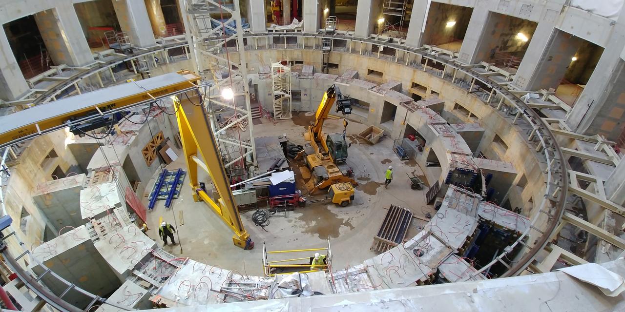
View of the concrete support ring of the reactor in September 2018, literally one week after its completion. The photo does not convey the sensation of scale at all, a little better can be understood from the short video I shot
- However, even before the construction was completed, the finishing on the lower floors of this building was completed - floor B2 is already ready for installation of numerous pipelines, cable trays, supports and equipment.
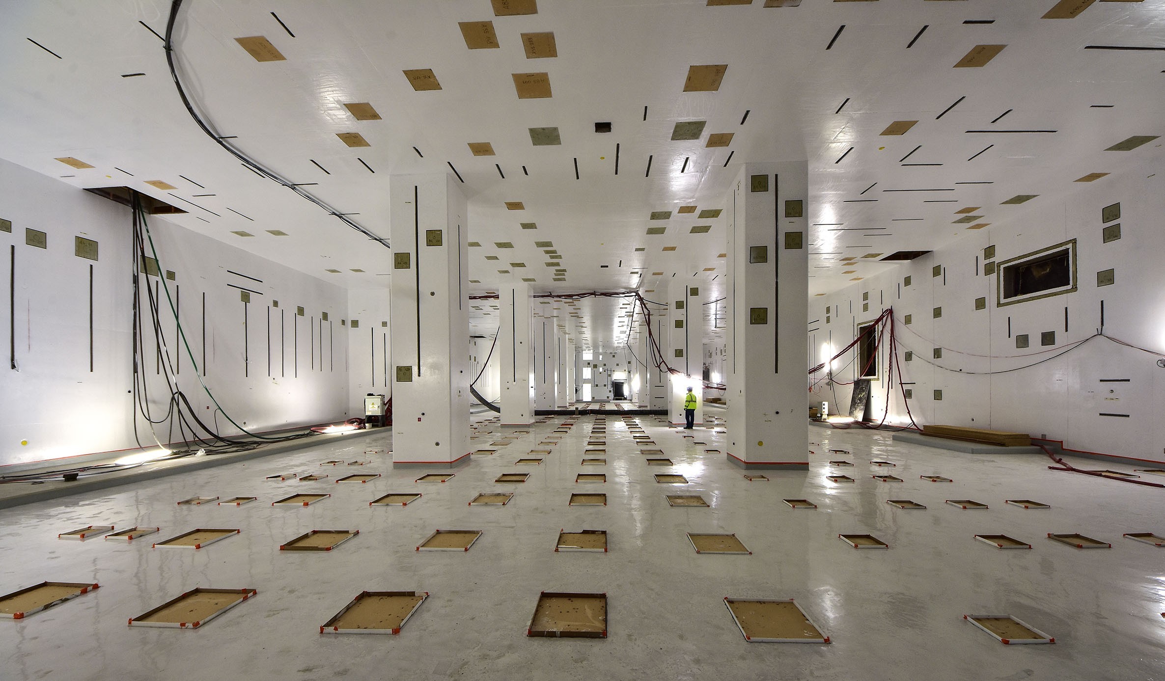
Lower floor B2 of the diagnostic building B74 is ready for the beginning of the installation of the equipment
- In 2018, the tokamak building’s saturation with non-recoverable elements also continued - in particular, 5 giant drainage tanks of the tokamak water cooling system and a superconducting feeder (vacuum tube with electrical and hydraulic communications) of Poloidal No. 4 magnet took their places.
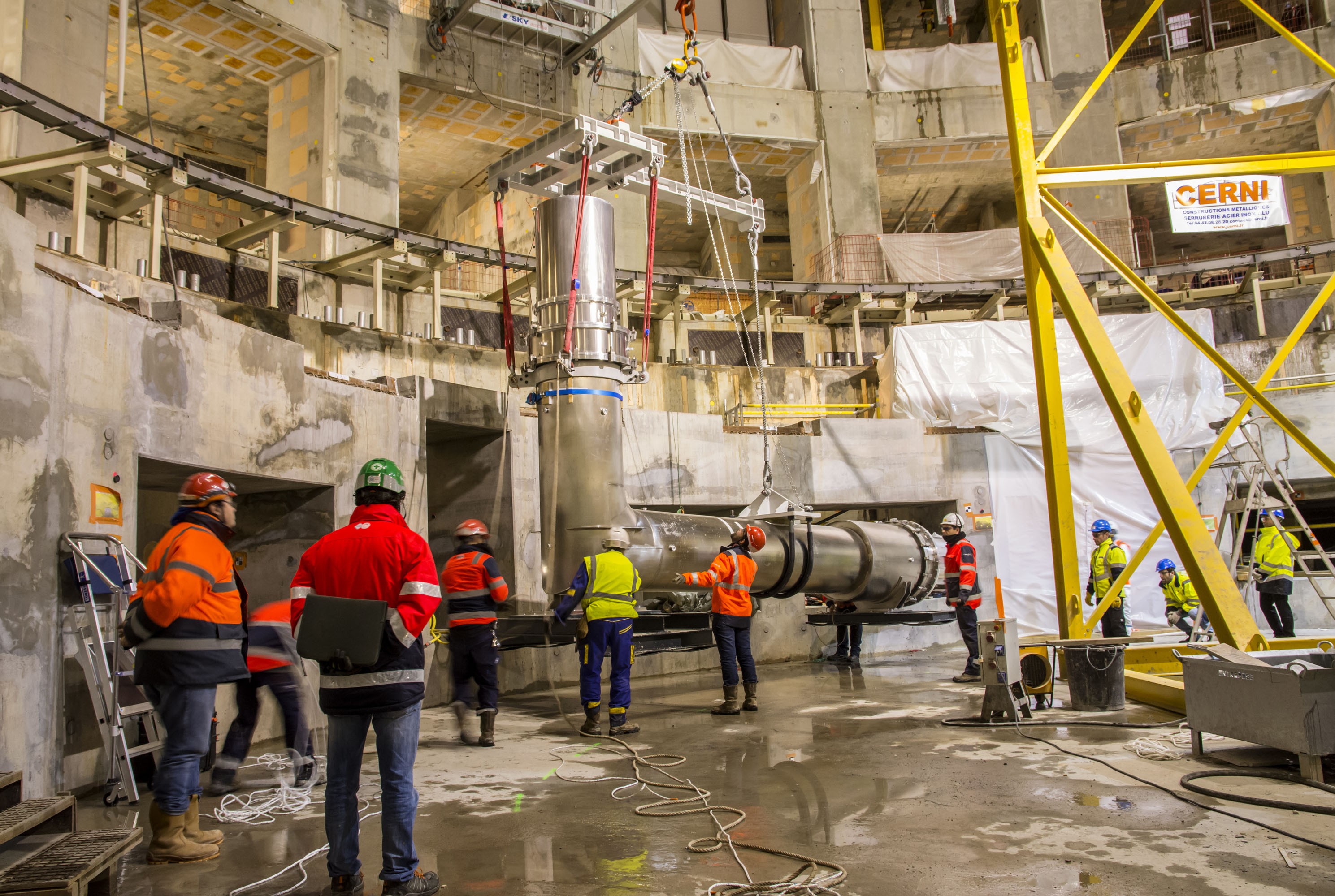
Magnetic Feeder Segment
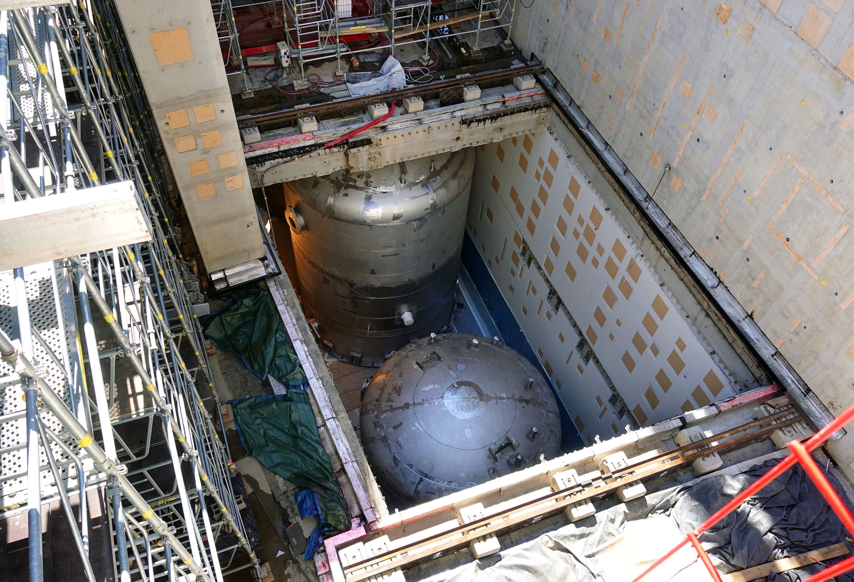
Drainage tanks and condensers of the tokamak water cooling system. The photo is not clear, but these are impressive tanks with a height of 10 meters and a diameter of almost 5.
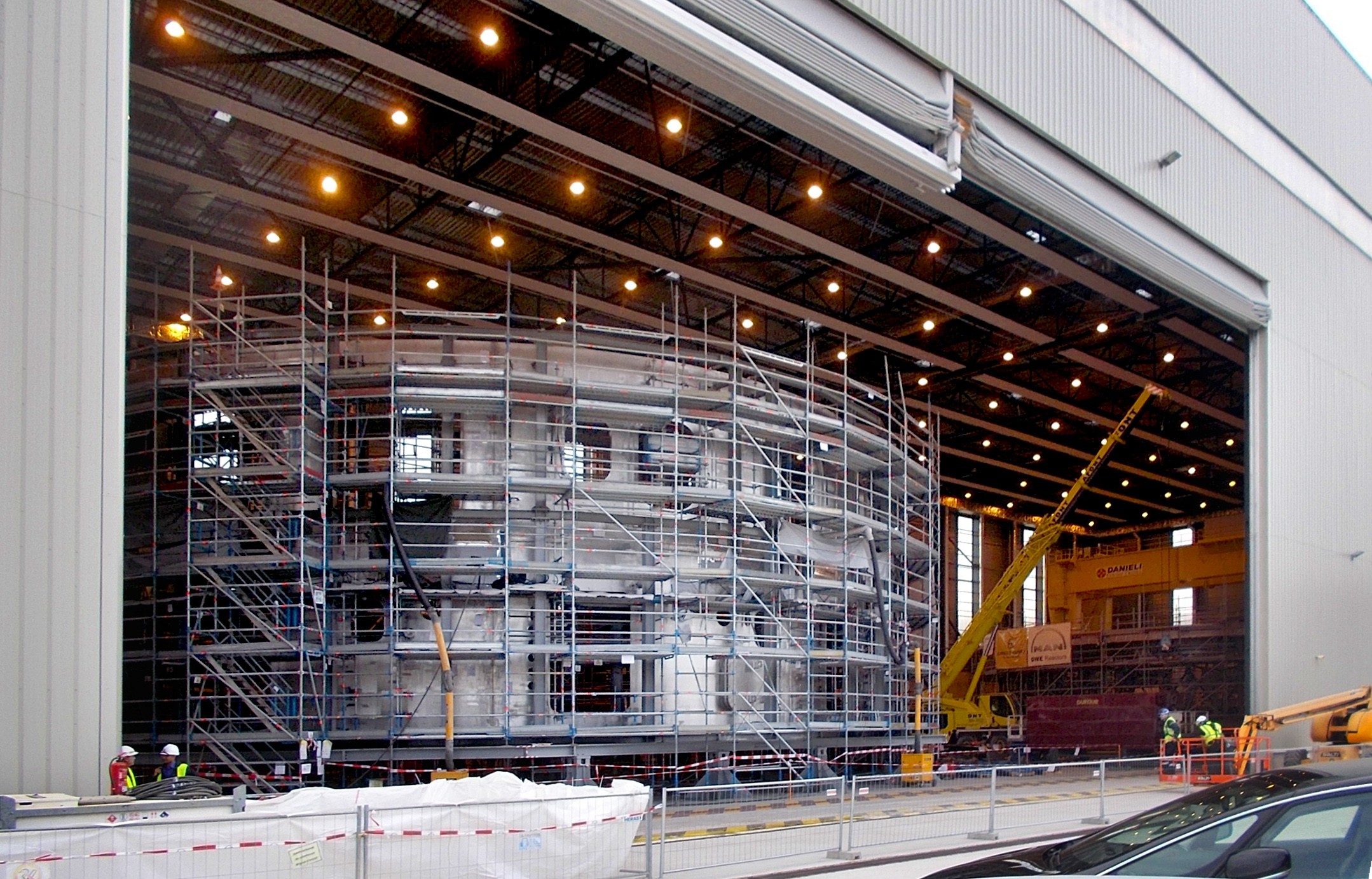
- In the pre-assembly building, the assembly of the assembly booths of the reactor sectors continues - this is going much slower than originally planned. These stands are really not simple devices - their task is to dock the three 300+ tonne elements of a reactor segment into a single whole, for which they have a lot of powerful drives, including platforms with 6-axis toroidal magnets positioning. However, a long fuss brings sad thoughts that everything is not as good as intended, with the design of the ITER assembly.
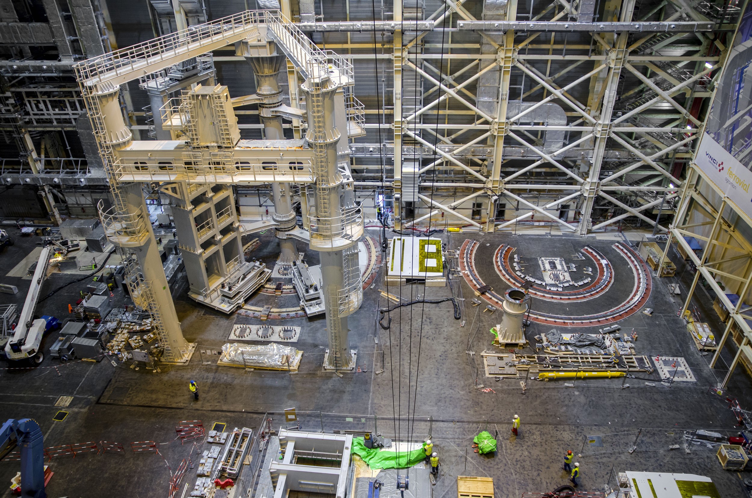
Work on the first assembly stand has been going on for over a year.
- The ITER cryogenic plant in 2018 passed through a grand installation of all large-sized equipment - an absorption generator of nitrogen, gas holders, cryogenic tanks, cryorefiguration columns, as well as less noticeable, but no less serious equipment inside the building: compressors, turbo expanders, heat exchangers, nitrogen and helium purification systems. However, by the fall of the activity in the building fell heavily. The problem is due to the fact that the ventilation-conditioning subsystem of the building is now in redesign, which means it is impossible to carry out many works.
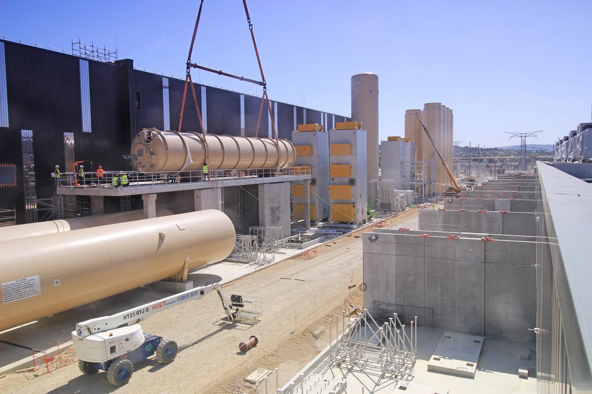
A 125-cubic meter liquid helium tank is one of the last elements of a large-sized cryogenics equipment.
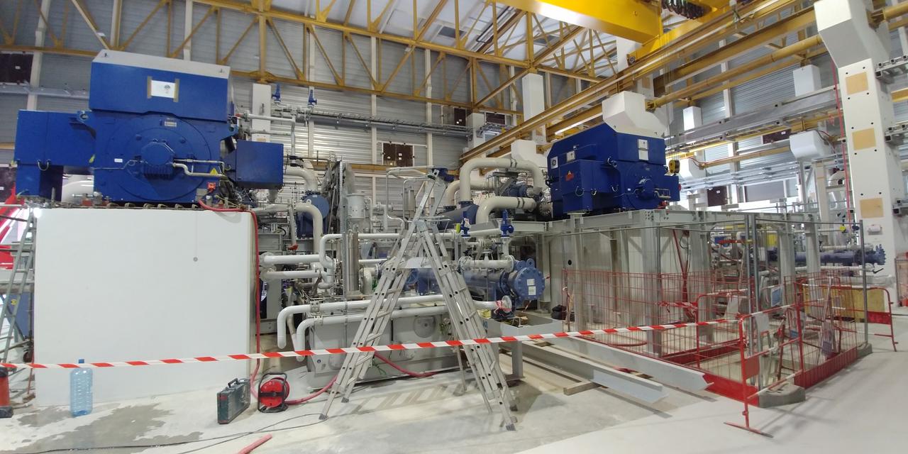
6 MW Nitrogen Compressor with Heat Exchanger Trim
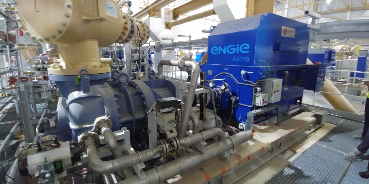
And this is one of 18 helium compressors with a capacity of 2.5 megawatts. If you look closely, you can see that the electric motor is undocked, because final
installation will be after completion of all pipelines.
- Small within the framework of the project, but an interesting moment - the installation of bioprotection doors has begun - huge hundred-ton structures that will close access cells to the reactor and quench the remains of neutron and gamma radiation.

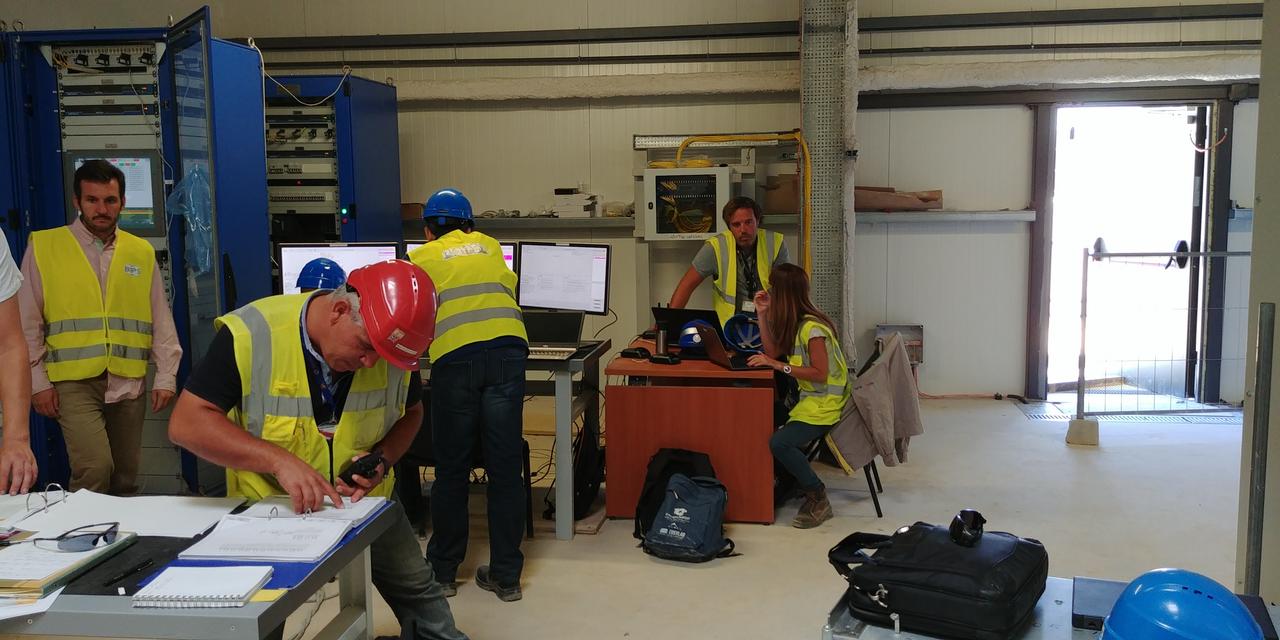
- Not bad in 2018 advanced electrician. The building of a distribution substation of constant loads was launched, through which ~ 110 megawatts of constantly operating devices — pumps, fans, low voltage sections, etc. — will be provided.
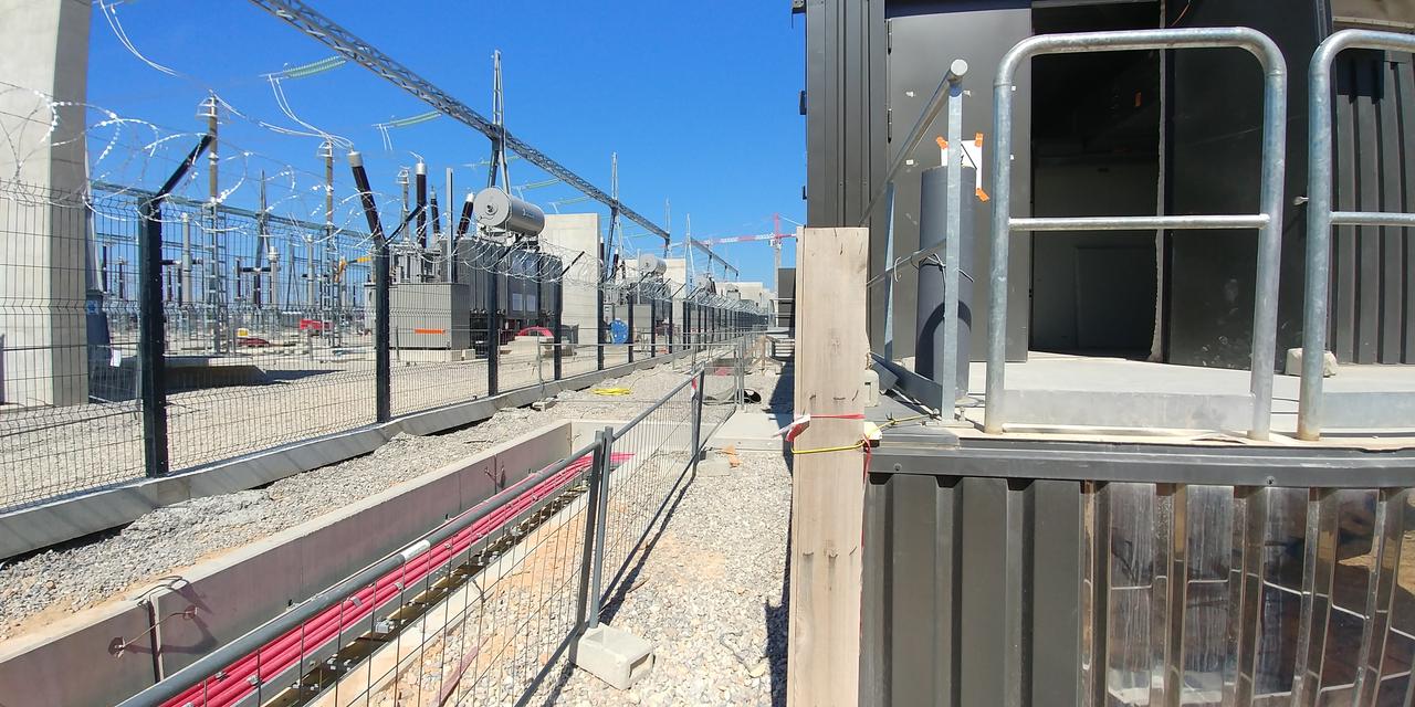
Corner of the substation building of constant loads. The scheme provides for the connection through 4 transformers and the distribution of energy at a voltage of 22 kilovolts. Inside the dreary rows of cabinets and, surprisingly well - commissioning of the control system
- The construction of an additional system of underground galleries continues on the site - the fruit of the next processing of the projects of power supply networks and equipment cooling. In 2019, this activity should end, and the site will gradually become more and more beautiful (however, in my opinion, the architecture of buildings is already otpadnaya).
- The heat release system (with a capacity of 1,150 megawatts) was completed in the construction part in 2018 - and although there is a delay of at least six months from the schedule, in 2020 it will probably be launched.
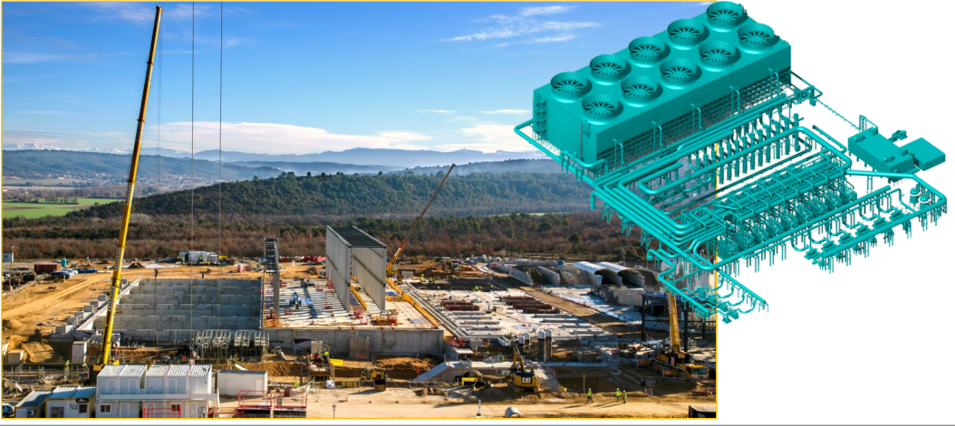
Panorama of the construction of the heat release system in the spring and the model of what will be installed here. In general, the systems consist of 20 fan cooling towers, two buried buffer pools for cold and hot water, and more than 30 powerful pumps and heat exchangers.
The same at the end of the year. The cooling towers are already being assembled, but they have not yet begun to assemble the interlacing of pipes and equipment.
Equipment manufacturing
- The first element from which the tokamak assembly will begin in 2020 should be the base of the cryostat laid on the support ring at the bottom of the reactor shaft. Having stood on this ring, I can note that the 30-meter diameter of the part completely erases the feeling that this is a machine-building product. In 2019, the base of the cryostat should be completed in the basic geometry, however, it seems to me, the welding of small elements - sensor mounts, heat shields, cables, etc. will not allow to begin assembly of the reactor in the first quarter of 2020. However, many other problems compete for the shift of this date.
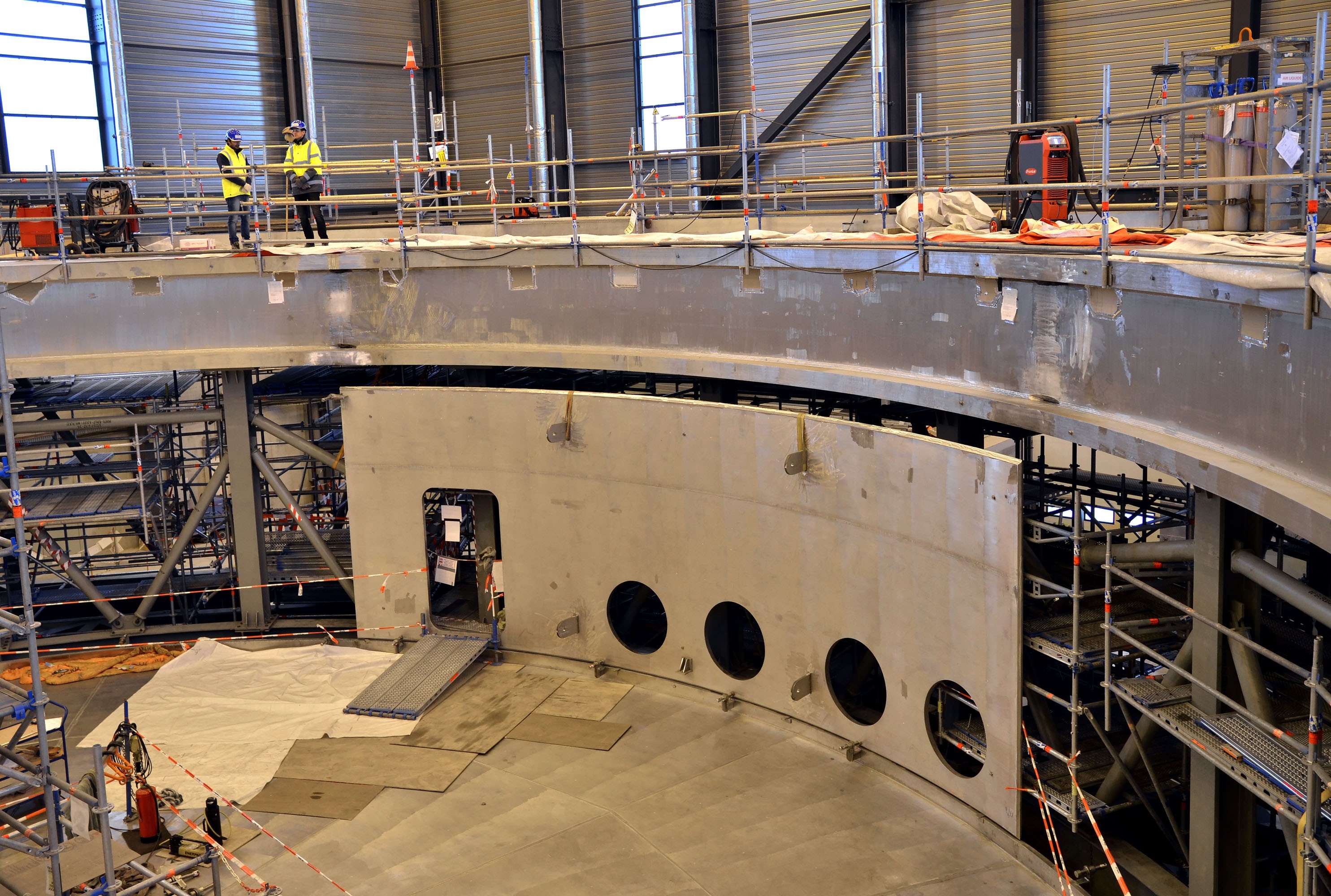
At the moment, the bottom of the base and the support ring are ready and an exhibition and welding of the intermediate shell of 5 meters height is taking place.
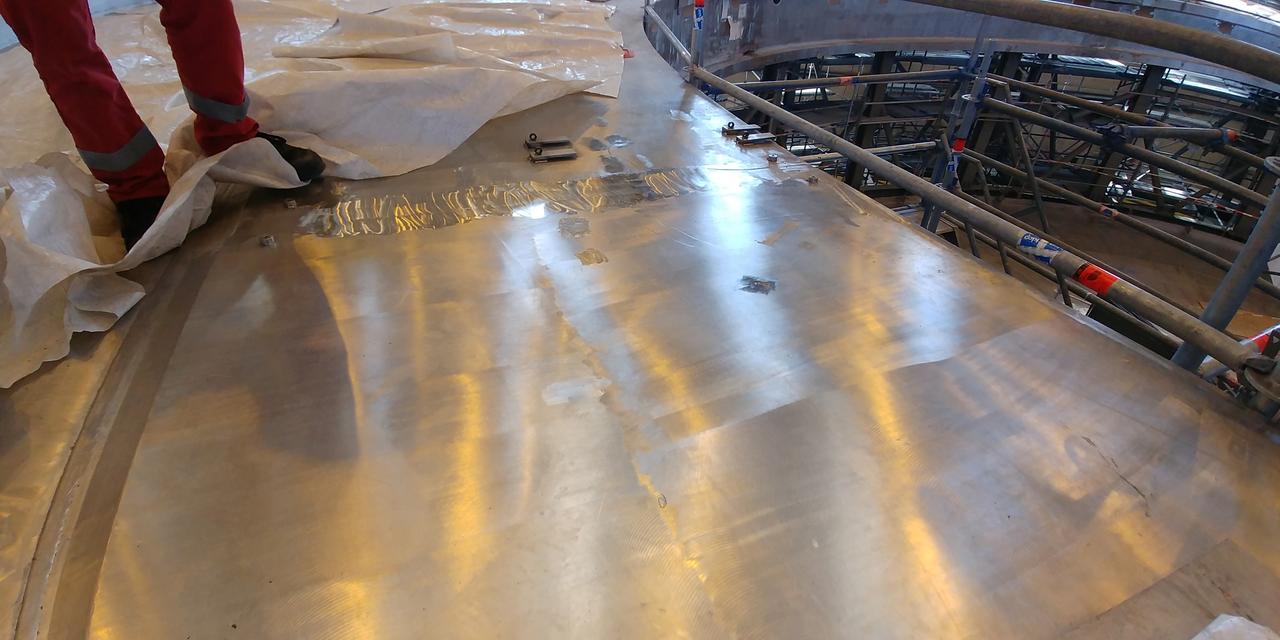
My shot frame welding two ring segments. Here the thickness reaches 200 mm, since on this ring there will be supports of the vacuum chamber and toroidal rings (in fact, the entire reactor weighing about 15,000 tons). In this ring, a lot of rather big holes for fastening bolts are still to be drilled - this can be done after welding the entire base and aligning the geometry.
- On the next slipway with the base in 2018, the second bottom “detail” of the cryostat was assembled - the lower cylinder. In general, this moment pleases, welding took about 1.5 years, and met the deadline.
Again, the photos are not able to convey the scale of these details. Even alive and with prior knowledge of dimensions, this does not seem to be engineering products.
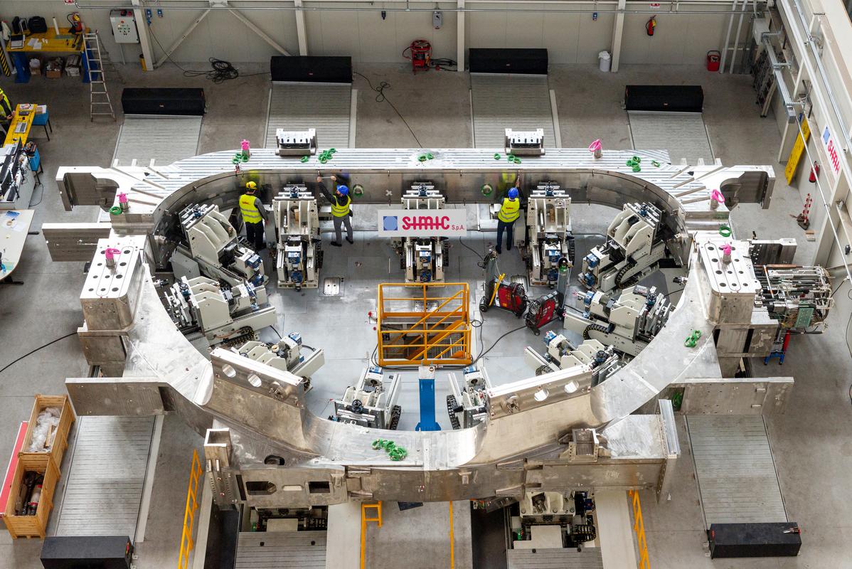
- The impressive progress in the production of ITER superconducting magnets is continuing, and I am not tired of repeating the most magnificent magnets in the history of mankind. If 2017 ended with the readiness of the first winding package (ie, the superconducting part) and the first power case of the toroidal field magnet , by the end of this year the package had been cryotest and assembled into the case of the toroidal field coil.
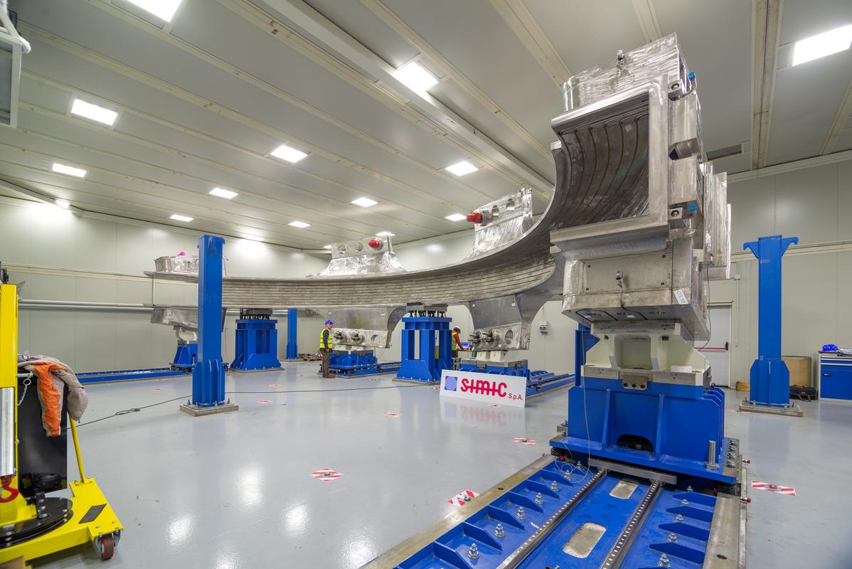
Semi-hull toroidal magnet.
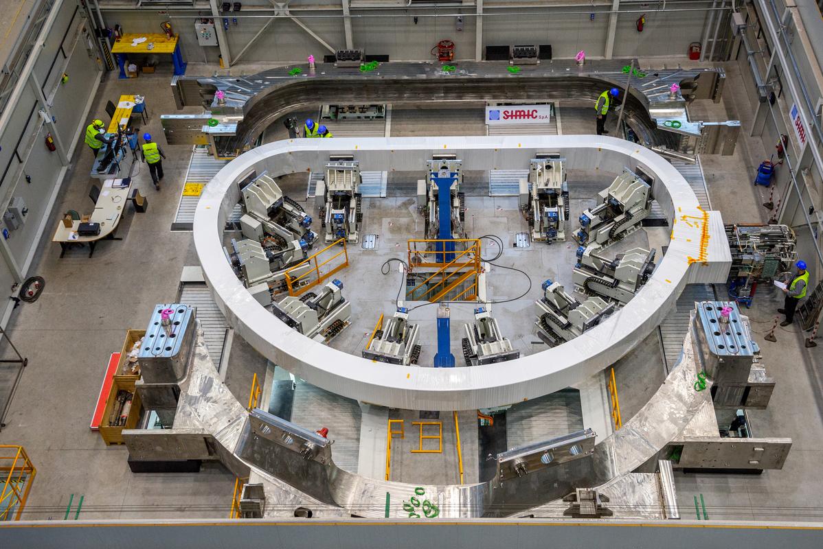
In 2019, on this combined case, it is necessary to brew all the joints, fill the space between the package and the case with epoxy resin, mechanize the case to the final size and carry out final tests - at the end of 2019 the first (of 18) TF coil will go to the installation site, will be a grand victory.
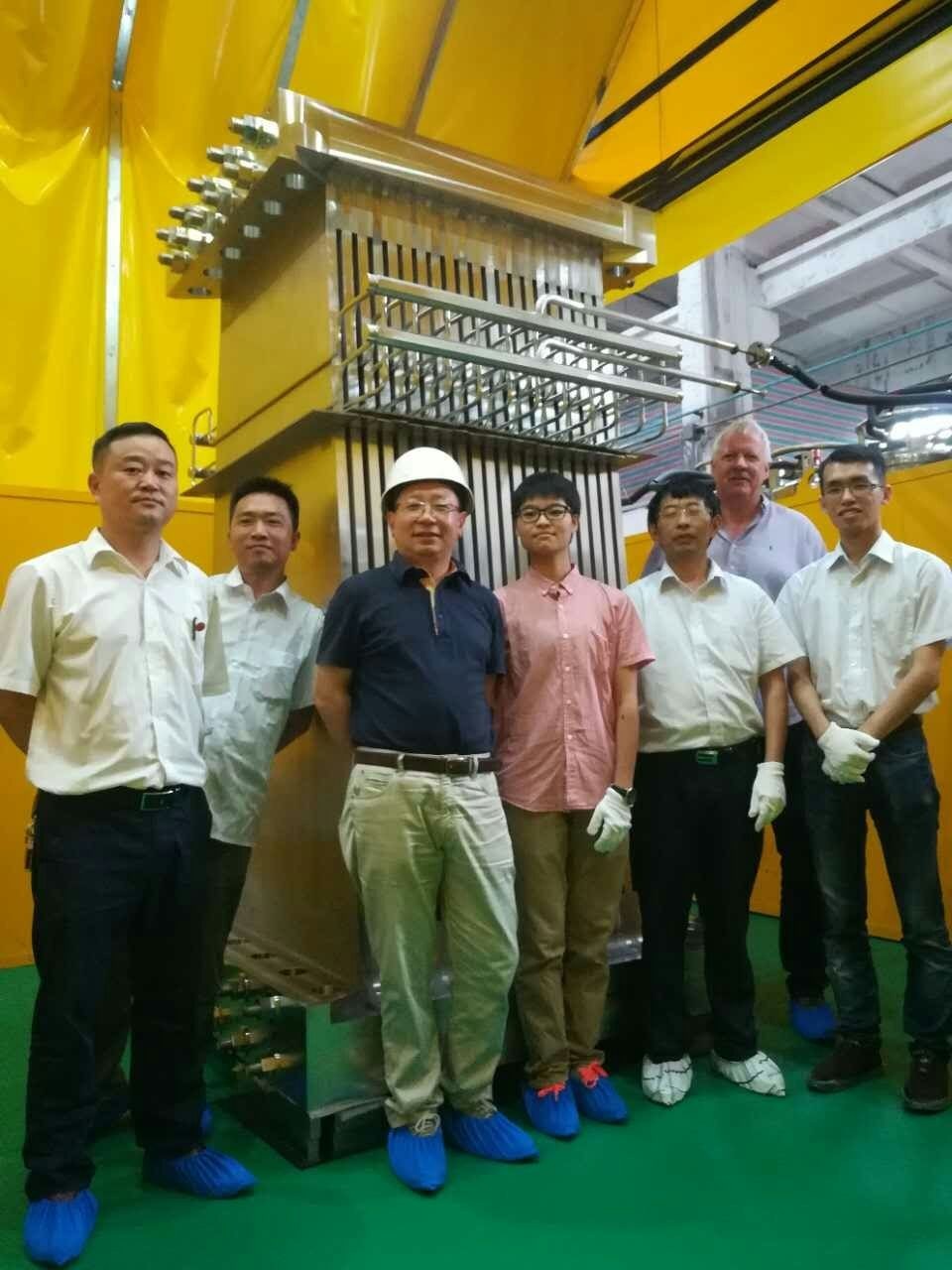
- At the same time, production of slightly weaker and simpler (but no less ambitious in size) coils of the poloidal field continues - PF6 in China (all the biscuits are ready, that is, the modules from which it is assembled, the entire structure is being assembled), PF5 at the ITER site (6 out of 8 gallets are already wound), PF1 in Russia .
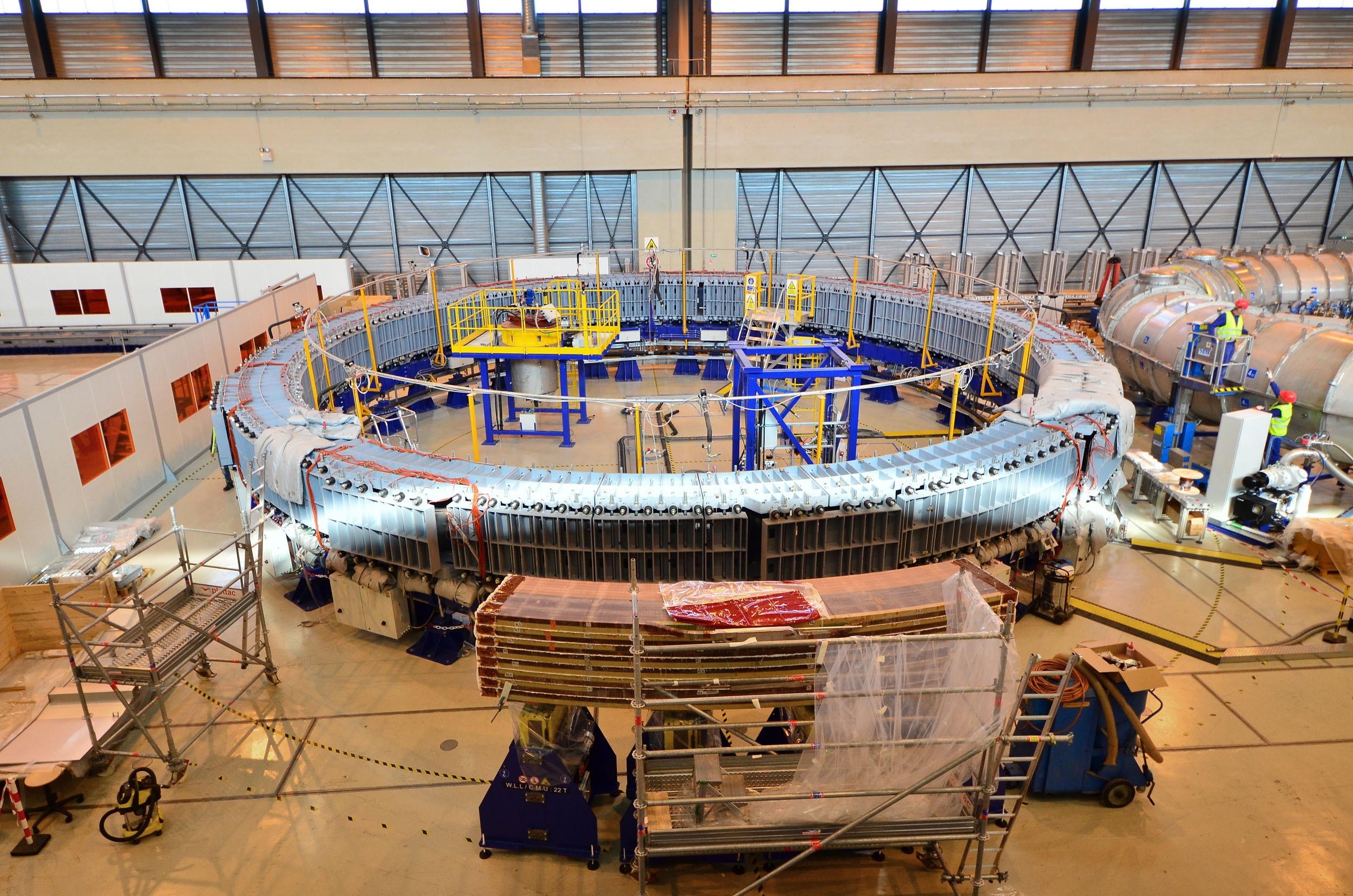
Layout in 1/8 of the future superconducting coil PF5 made from the first prototype sawn into pieces against the background of a vacuum-injection chamber for impregnating the insulation of the entire assembly. On the right you can see a cryostend for testing future coils, which will be a little more than a year.
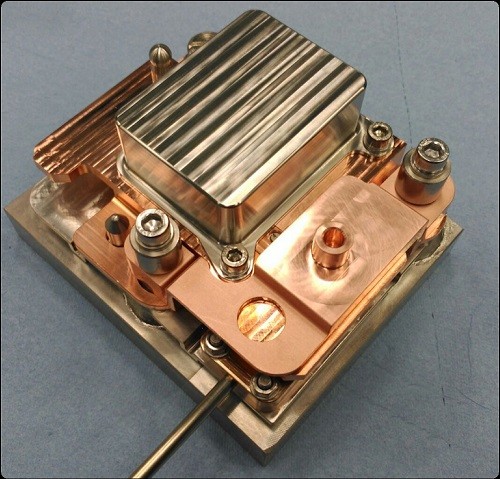
- In the United States, the creation of the world's largest magnet continues - the 1000-ton Central ITER Solenoid , which will consist of 6 modules. In 2018, the creation and adjustment of the last technological post of production (a cryostand where the modules will be tested for tightness and ability to withstand operating current) was completed, a copper model was tested on it, after which it was sawed and made sure that all production was carried out correctly. Already in 2019 the entire chain will pass the first module, and in total 5 out of 6 are already in production.
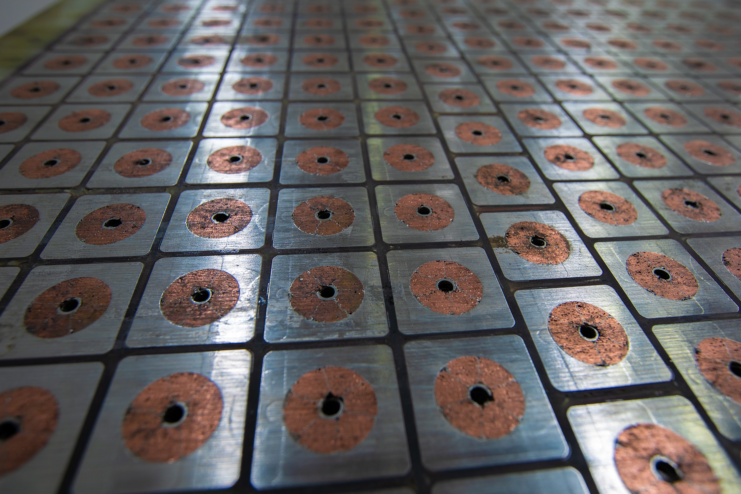
The sawn model of the central solenoid module. More than 400 turns of superconducting cable with a maximum current of 55 kiloamperes in a very stiff steel jacket are separated by fiberglass electrical insulation, which must withstand up to 15 kilovolts without breakdown.
- The ITER magnetic system will have a heavy-duty power element of six fiberglass rings with a diameter of more than 5 meters and a section of 350x350 mm, which will provide the necessary rigidity of the magnetic system against pushing ponderomotive forces. To test the rings in 2018, a stand was built that can create a bursting force of 36,000 tons.
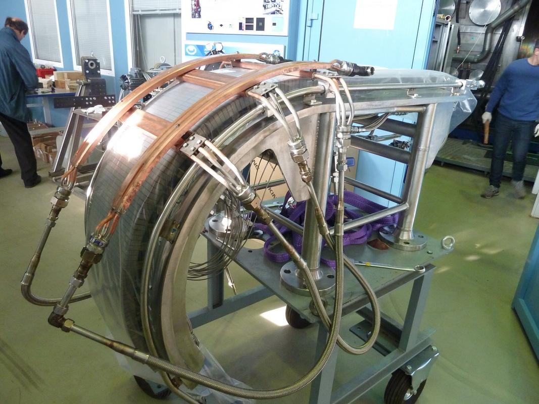
- Europe in 2018 completed the creation of a prototype of the largest cryosorption pump in the world - a vacuum pump, which will maintain the working vacuum in the toroidal chamber. A contract has been signed for the supply of this one of the key elements of tokamak.
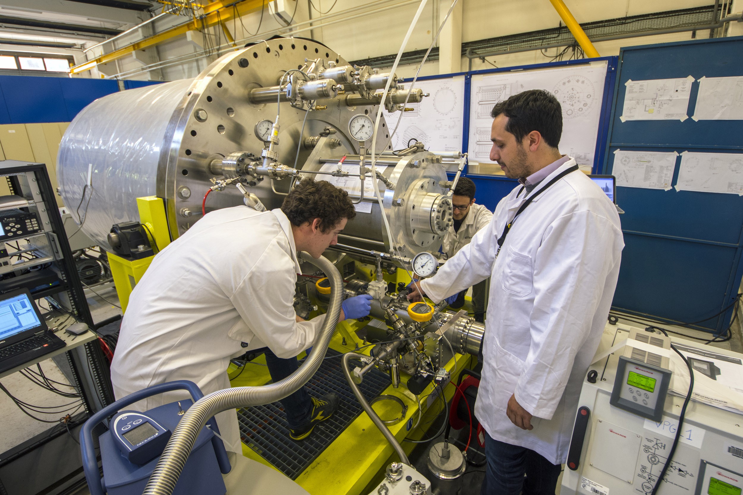
Test cryosorption pump in the laboratory. The weight of the device - 8 tons, length 4 meters, diameter - 1700 mm.
- Also, Europe (responsible for the creation of almost half of the ITER equipment) produced in 2018 a prototype divertor cassette and one of the divertor plasma targets. Let me remind you that the divertor is responsible for pumping the plasma for constant cleaning of “thermonuclear ash” - excess helium and contaminants that the plasma suffices from the walls.
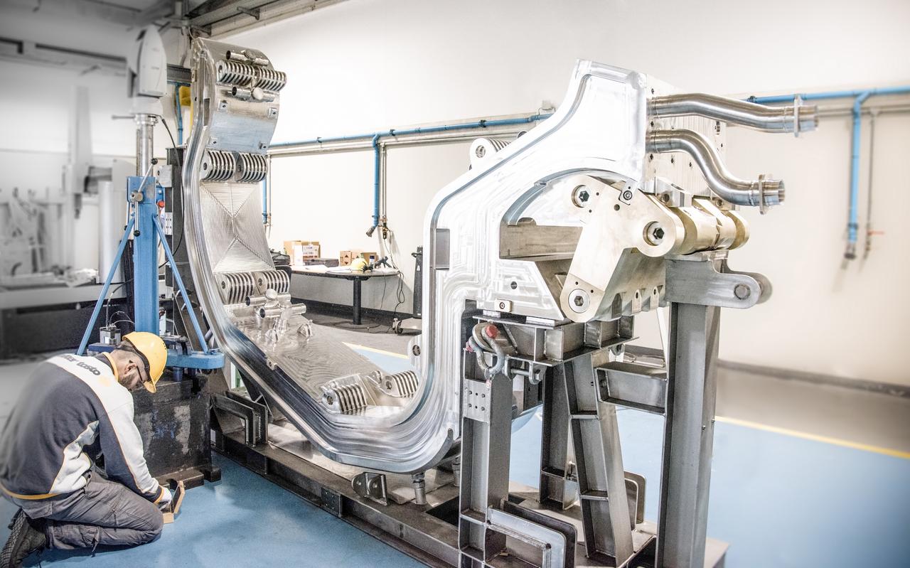
Divertor cassette case. Inside this thing will be cooled with water (it is hollow), and on top of it will be mounted three targets for incoming plasma, recruited from tungsten blocks, inside which are laid cooling tubes. Total divertor will consist of 54 such cassettes.
One of the three tungsten plasma targets made in Europe during thermal tests at the St. Petersburg Scientific Research Institute of EEA at the Cepheus stand.
Tungsten blocks of divertor surfaces
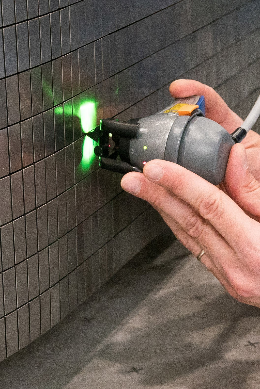
- An important, I think, trend of 2018 was the development of the production of many small ITER elements - primarily measuring sensors: magnetic field, currents, temperatures, flows of liquid helium.
This photo shows a magnetic field sensor intended for installation in harsh conditions inside a vacuum chamber (radiation, temperature up to 200 C, vacuum).
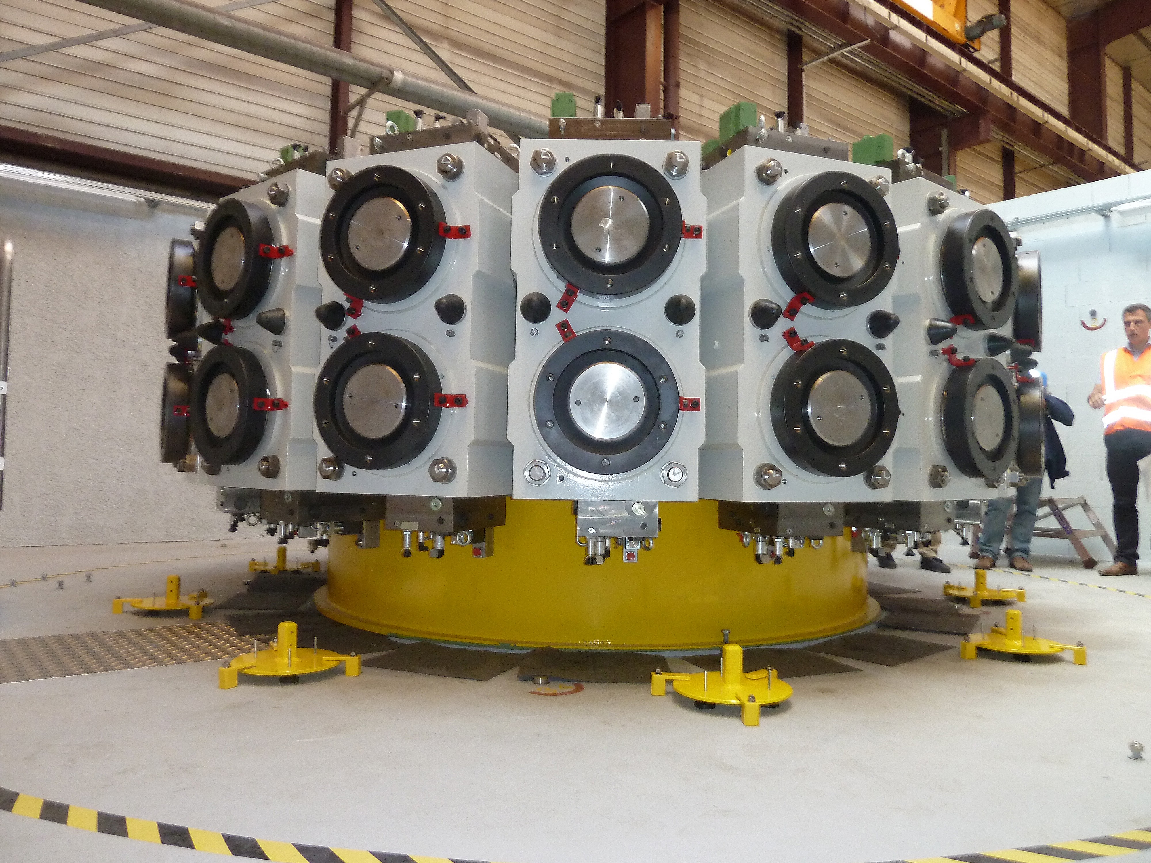
- China in 2018 produced the first supports of magnets - along with the fact that these are simply large, complex stainless steel products, they are also actively cooled and, on the whole, require fairly nontrivial metalworking. In addition, in China, the creation of the first corrective superconducting magnet, one of 18, is needed to improve the uniformity of the magnetic field and reduce heat loss by the plasma.

The correction magnet is lowered into its power case.
Bearing toroidal coil, which was collected above. In operation, the top of this support will be cooled to ~ 30 K and the bottom will be almost room temperature.
- South Korea is also engaged in metalworking in the project, which failed in accordance with plans in 2018 to complete the first sector of the vacuum chamber, an extremely complicated product weighing 300+ tons, representing a double-walled vessel of double curvature with walls of 20-60 mm. At the moment, the manufacture of the vacuum chamber clearly lies on the “critical path”, i.e. determines the timing of the project.
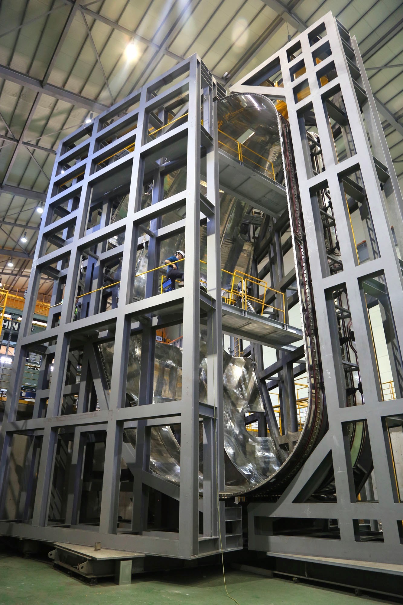
Actively cooled heat shields will separate the hot vacuum chamber and cold superconducting magnets. Thanks to vacuum and active cooling with helium to ~ 90 K, they will reduce the thermal load on the magnets by ~ 100 times. The photo shows the first screen sector in South Korea.

But the European small part of the future vacuum chamber (this is the part of the wall that forms the inner cylinder around the central hole of the torus is one of 9 similar segments)
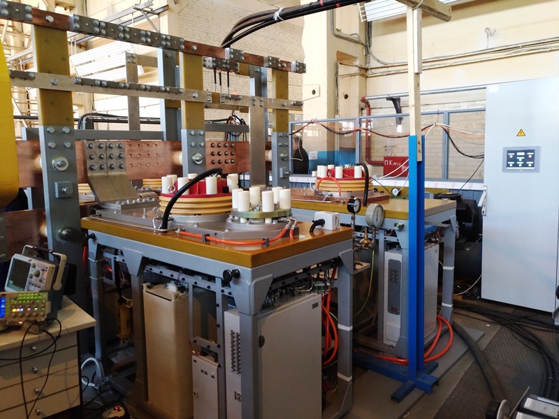
- In Russia, meanwhile, in 2018, the coolest high-speed current switches for 45 kiloampers and 8 kilovolts were successfully tested - they are necessary to create magnetic field surges needed to start a tokamak. In the coming years, several dozens of such blocks should be put on site for installation at the ITER site.
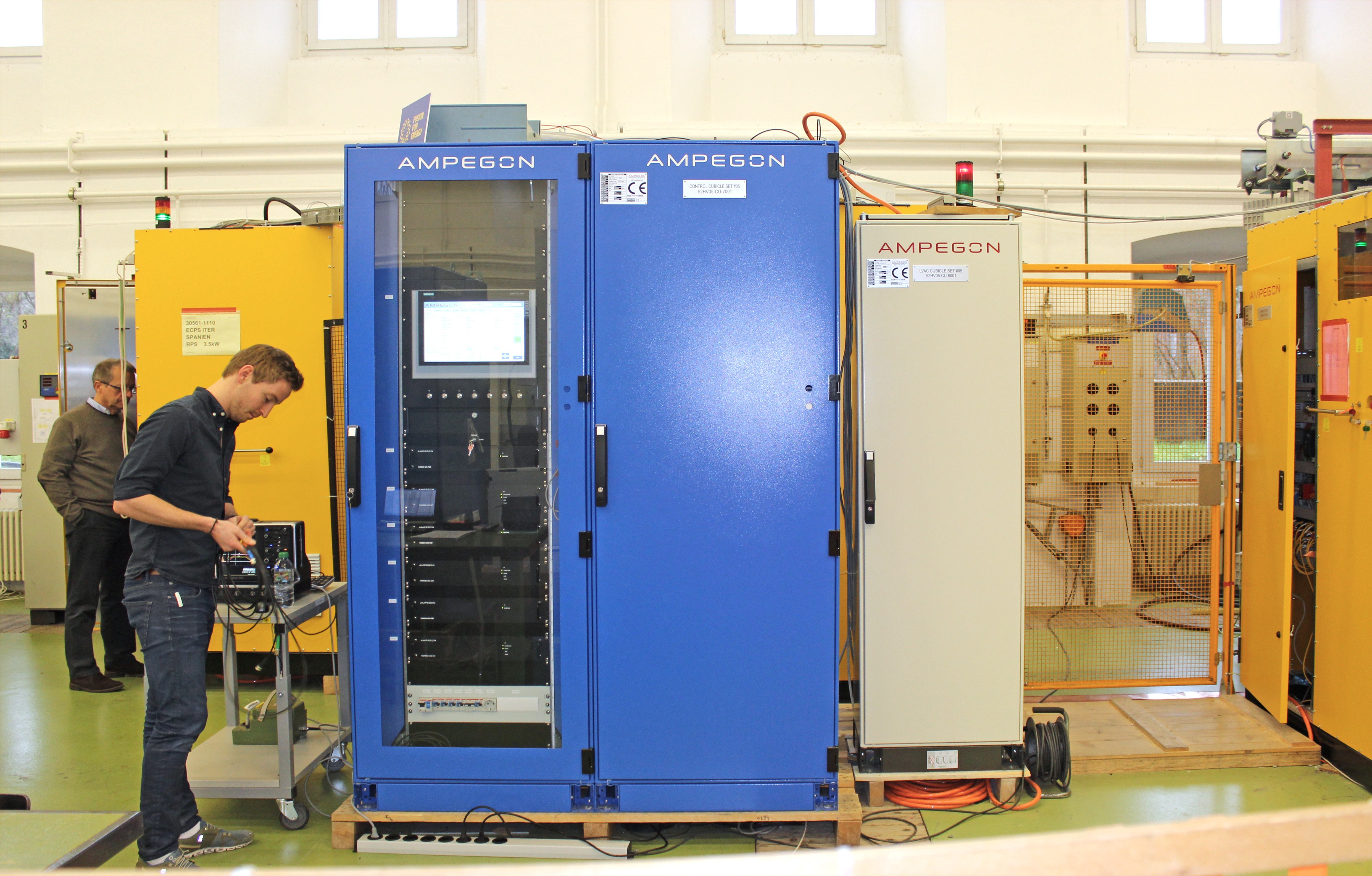
- In addition, gyrotrons continue to be produced and tested - megawatt radio tubes, 8 of which should be supplied by Russia, and which will ensure the breakdown and heating of the plasma in the tokamak. Interestingly, for both radiofrequency heating systems, high-voltage, high-power direct current sources are required, and for them in 2018 there were also successes, for example, a set of sources for a pair of gyrotrons was successfully tested in Europe.
- Finally, the news about the laboratory of testing neutral beams ( NBTF ) in Black ... uh, in the Italian city of Padua. Neutral beams of deuterons with a power of 30+ megawatts are the most important subsystem of plasma heating and one of the most high-tech nodes. This year, the SPIDER stand was commissioned in the NBTF laboratory, where the creation of long-term beams of negative ions with a current of up to 40 amperes (this is ~ 4 times greater than the current record) of the required geometry should be tested.
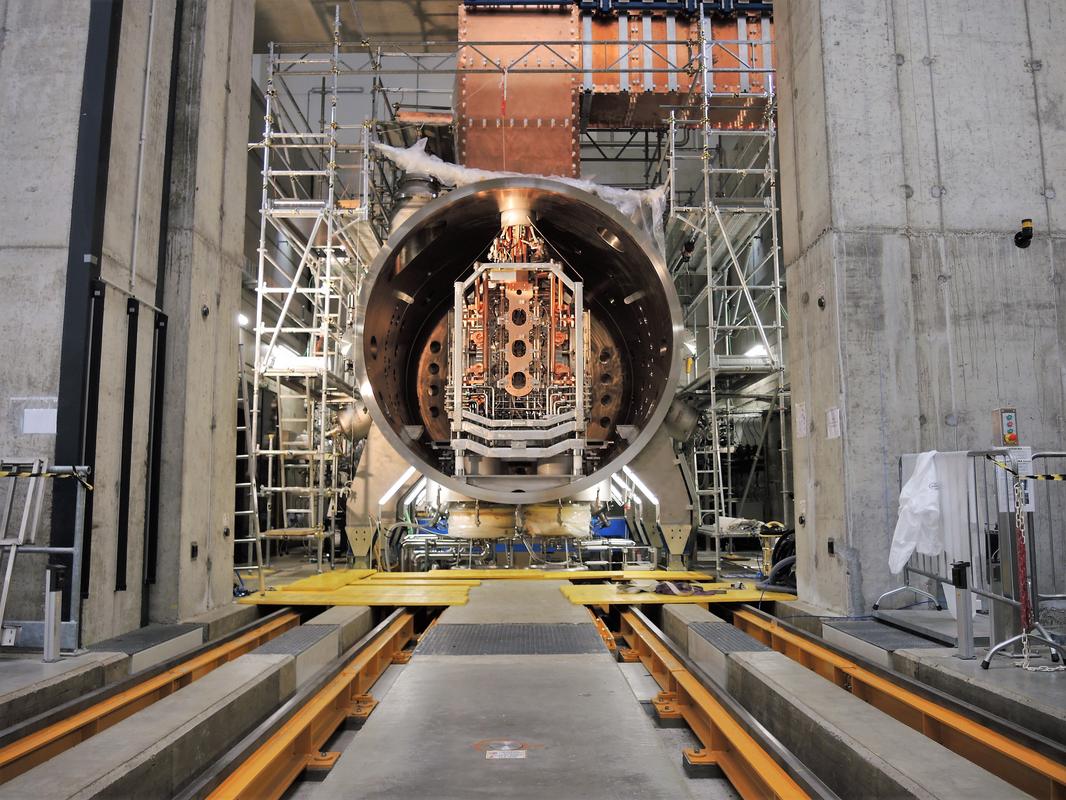
Stand SPIDER - vacuum barrel in the near end of which a source of negative ions is installed. On this side, you can see all kinds of electrical and hydraulic communications.
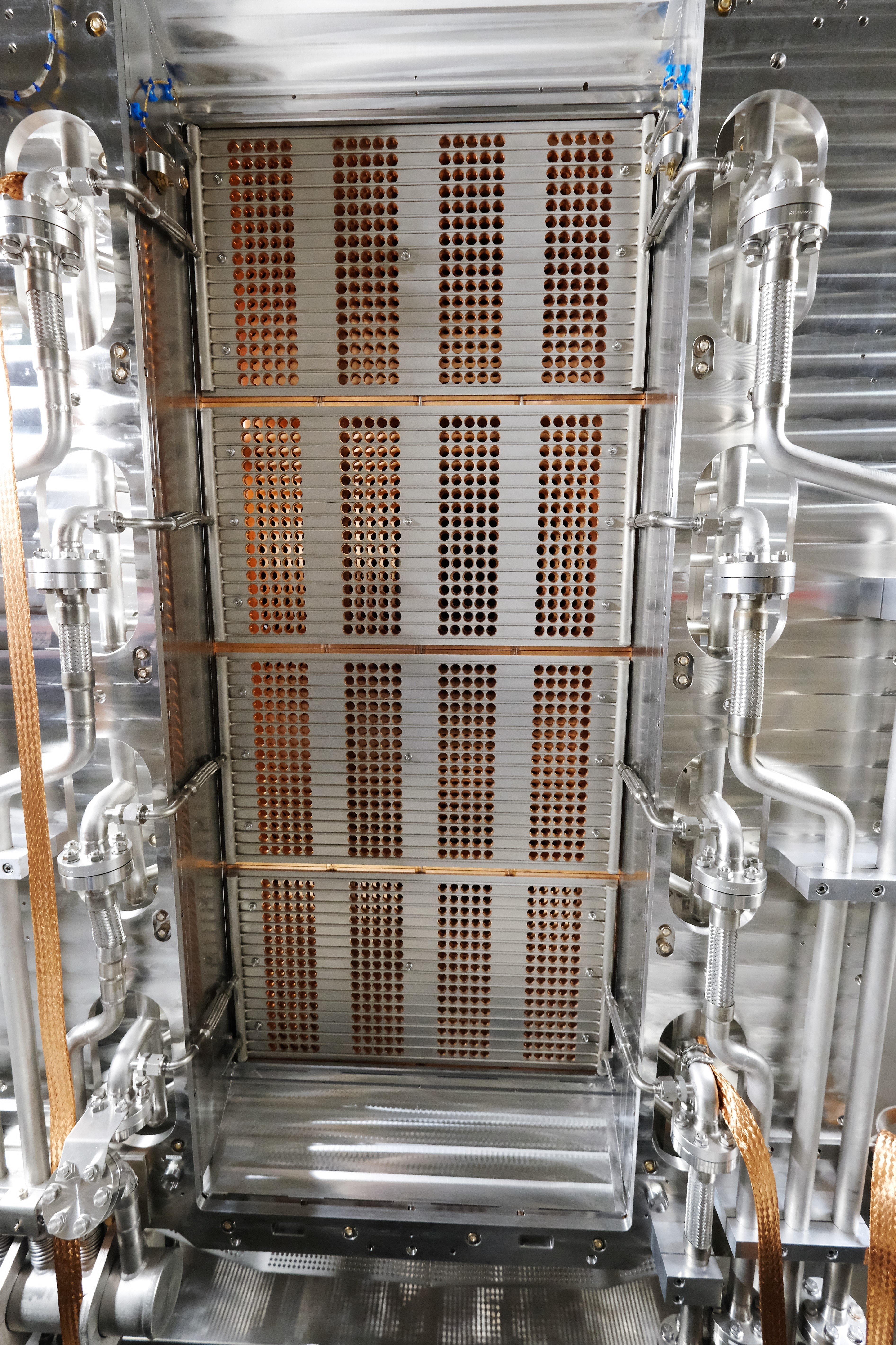
On the reverse side, small holes are visible through which the rays of negative ions will be electrically drawn out.
- In the same building, the next, even larger MITICA facility is being constructed, where beams will not only be created, but also electrostatically accelerate to 1 MeV, neutralize and be cleaned of residual ions - in general, everything that is required from the ITER neutral beam injector, only without ITER. In particular, in 2018, there was a great advance in the construction of a megavoltage power source of the accelerator system and placed an order for the industry on the internal intestines of MITICA.
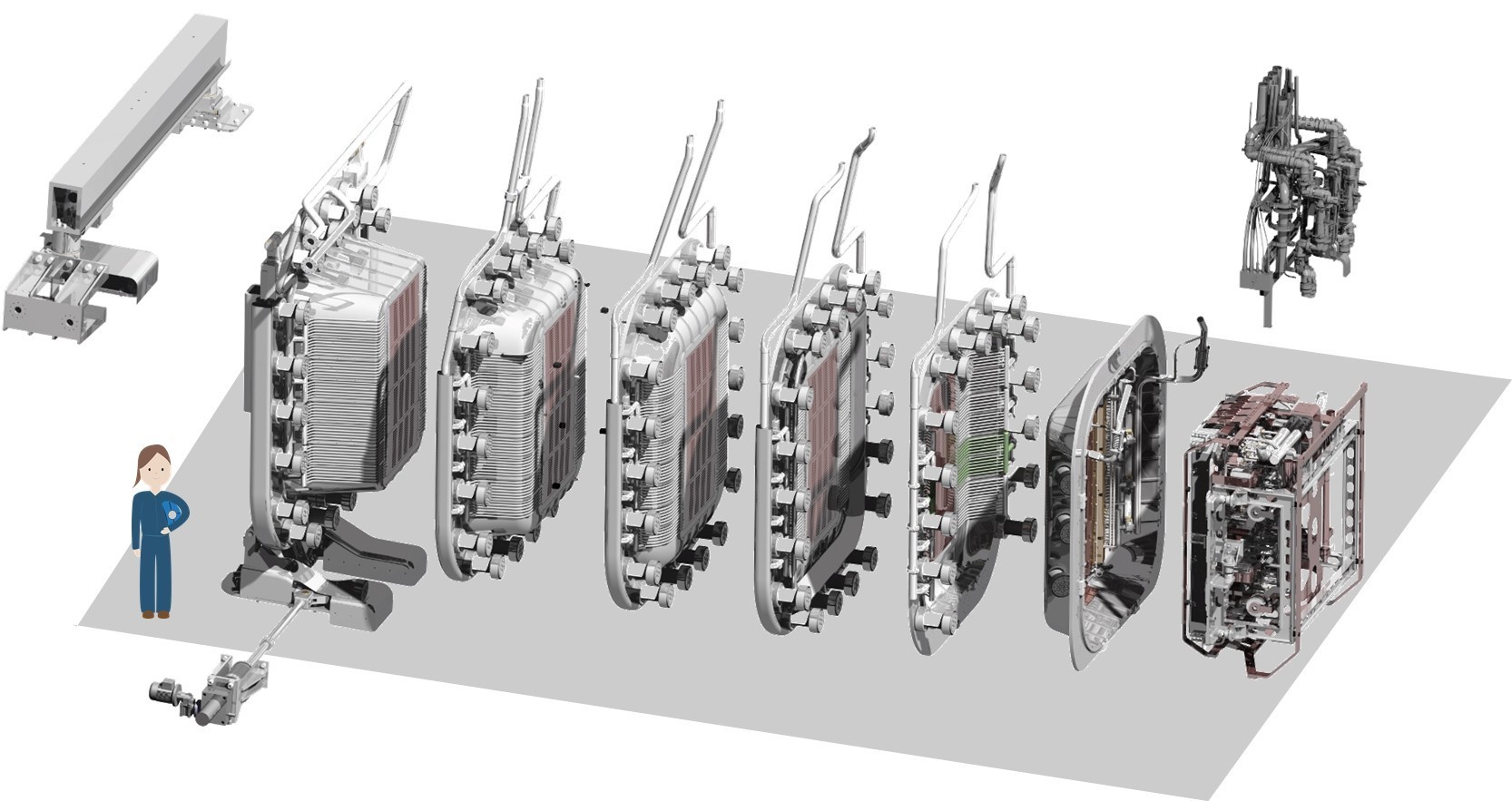
The elements of the MITICA accelerator system are a complex radio-frequency source of negative ions on the right and, on the left, conceptually simple but hellish accelerating grids that are difficult to manufacture, each of which is separated by a 200-kV potential from the previous one.
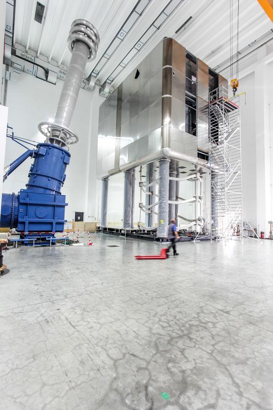
The high-voltage platform of the source of negative ions MITICA, which in operation will be at a potential of -1 megavolt.
Conclusion
Constantly emerging problems, slipping deadlines within the ITER framework, of course, cause both mild disappointment and doubts, however, it seems to me that this is the karma of any large project, all the more so record-breaking in many areas at once. The main thing is that the project is moving forward, and it is moving well, in most of the equipment’s positions, performing it on time and with the necessary parameters. Let's hope that the outlined difficulties with the planning of works and installation of equipment at the ITER site will go away and the date of the first plasma in December 2025 will not be too disrupted. Well, I will continue to talk about the project and, in particular, will soon write a detailed report on my trip to the site.
Source: https://habr.com/ru/post/435244/
All Articles