Pi-Sonos: a hobby out of control

The idea of the design of the new building of the Internet radio station Pi-Sonos was born before the completion of the previous version. Over time, she absorbed the accumulated user experience and took into account previously admitted shortcomings. This time everything is “grown-up”.
Please love and respect
Let's say goodbye with the name " Pi-Sonos ", and today we will continue to call the column " RadioBox ". And although this time Sonos Play 1 had the greatest impact on the development of the project, the new name, firstly, sounds better, and secondly, reflects its specificity and independence.
Motivation
It seems to be the case number 2 was more user-friendly compared with the first , but he, too, was not without flaws.
')
The main and principal were two of them:
- Button "play / pause" on the front end
The button is not the toughest, but nevertheless, when you click on it, the column very often moved from its place. - Analog Volume Control ("Twist")
The volume can be adjusted not only from the smartphone, but also on the speaker itself. The first method is digital, the second is analog. Accordingly, intermittently appeared between them. It was especially frustrating cases when someone twisted the analog volume to 0, and then no matter how much you poked into the smartphone, you could not do it louder, you had to get up anyway and go turn the knob.
Consequently, it was necessary at least to replace the analog twist with two numeric volume buttons, and move all three buttons to the upper end. By the way, in Sonos Play 1 it is done that way.
Here are added two more Wishlist. The first is the smooth flashing of the LED in pause mode. The second is a different color of the LED during the loading of the column, so that without a smartphone it is clear when the column is ready for use after switching on.
And last but not least - I wanted a beautiful case with a minimum number of seams, smooth lines and a stylish design. I wanted to repeat the aesthetics and conciseness of Sonos.
Process
Housing
The sketch at the beginning of the article is a real sketch of the future corps. Phase-inverters are not traced there, but the volume of the case is already calculated for the existing speakers and the places for the speakers and electronic filling are allocated. Smoothed corners are a real challenge for me. Whatever one may say, it’s impossible to glue this from individual walls out of 8mm MDF ( I do not consider other materials for two reasons: 1) the ease of processing this MDF; 2) the absence of other normal materials in stores in my area ). I had to completely change the approach to the manufacture of the body.
This time I had to apply the technology of gluing layers. It is simple to indecency: we dissect the entire body with horizontal planes with an interval of 8 mm and cut out the resulting projections from MDF. The mastermind behind technology, as always, is the SoundBlab channel. The main advantage of this approach is that you can immediately make a lot of cameras of almost any shape (for example, phase shifters are very convenient to do). But as you know, the devil is in the details.
The height of the case with all the “covers” is 168mm, MDF is 8mm thick, i.e. need to make 21 layer. No not like this. It is necessary:
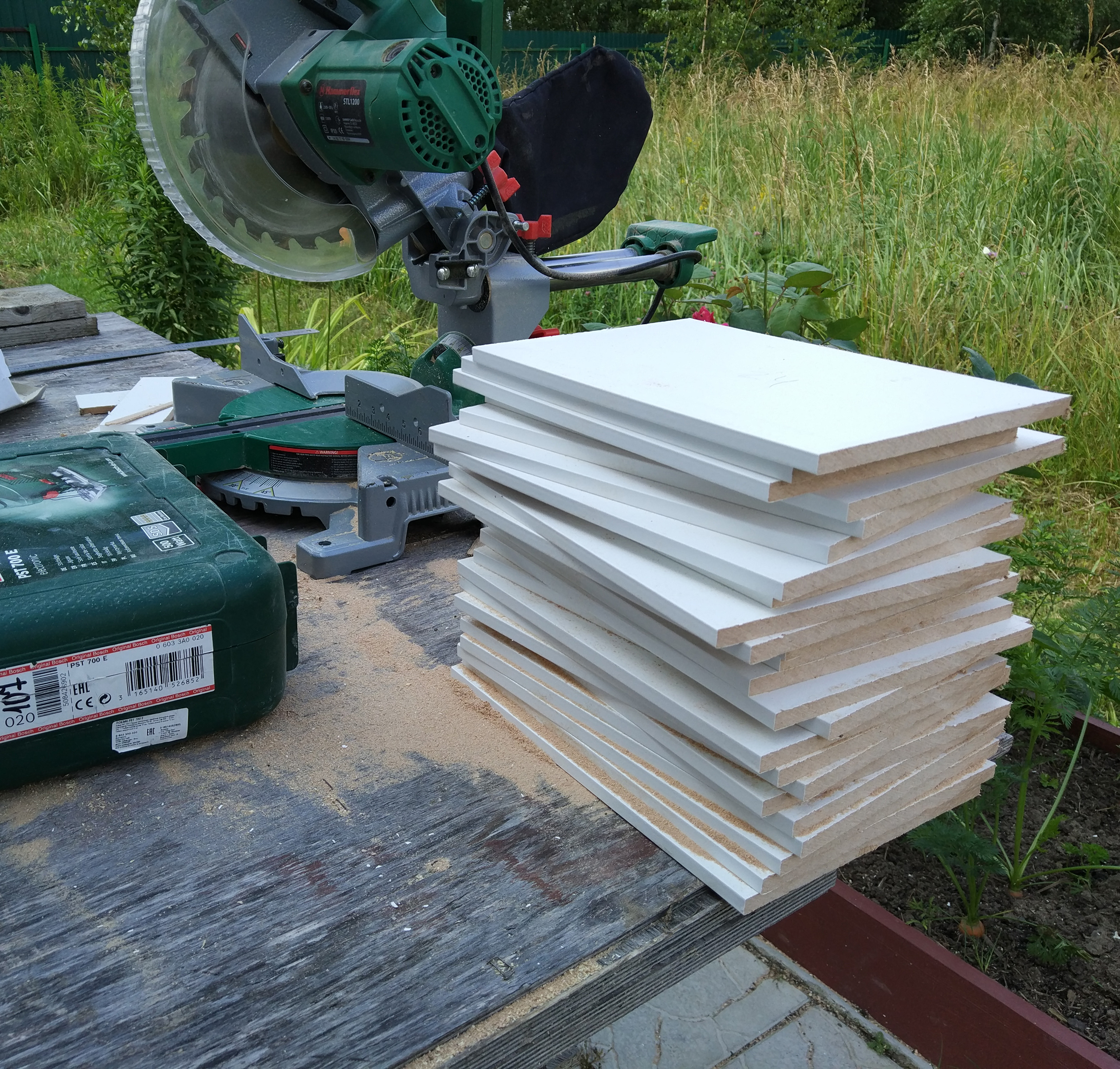
- sawed MDF panels into 21 blanks;
- then make 21 parts of a certain size (i.e., milling 63 faces, 3 faces on each part, one face was initially flat, and therefore starting);
- then cut with a mill with 84 angles according to the template;
- next - cut about 50 holes of different size and shape;
- then glue all the parts into a single case;
- and drill and drill holes for the speakers and ports of the Raspberry Pi;
- finally, putty, sanding and painting the case and covers;
- and only then can one calmly proceed to the assembly of the components inside the case and the "finishing" finishing of the column.
If there were no problems with the saw (on the miter saw of claim 1, it took about 10 minutes), then some difficulties started. For those who do not encounter wood processing, I will explain: to make more than 2 strictly rectangular parts of exactly the same size and shape using only a milling cutter and a ruler is very difficult.
It was possible to make one detail, and then use it as a template (something like this ), but then (as you can see by example) you can only process 2 faces out of 3x at a time, and then you need to rotate the workpiece, which still threatened to "knock down the sight" and do something crooked.
In practice, it turned out to be easier and better to assemble your own small milling table and mill the parts already on it.
A little about the table for those who are curious
In the assembly of the milling table is nothing complicated. The material of the tabletop was the remnants of laminate - it is quite hard and gives a perfectly smooth surface. For the frame used planed bar 30x30mm. 2 frames, 4 with small stiffeners - et ... voilà :
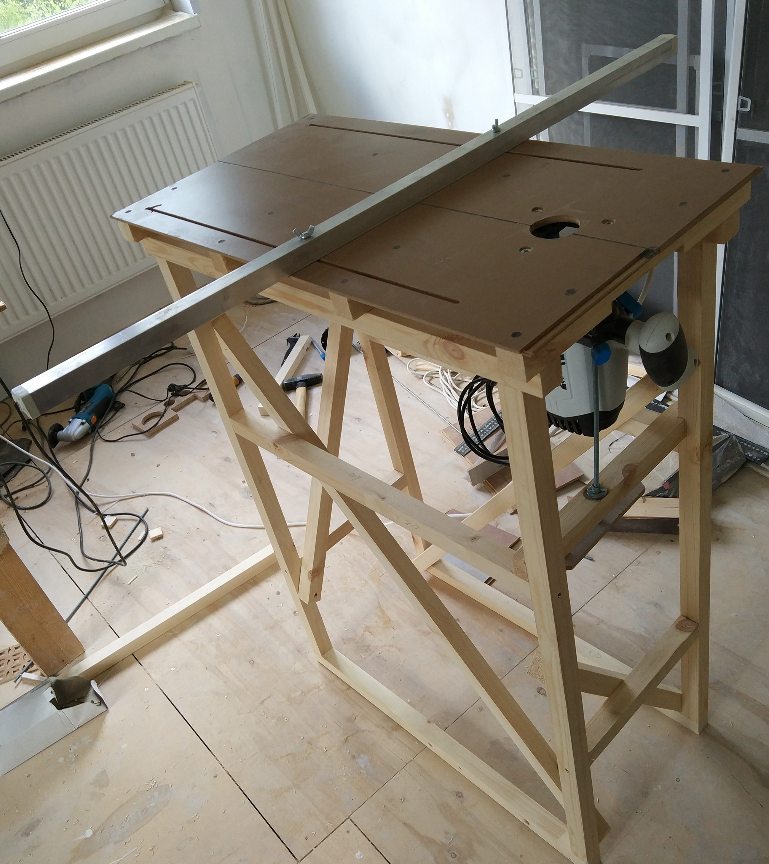
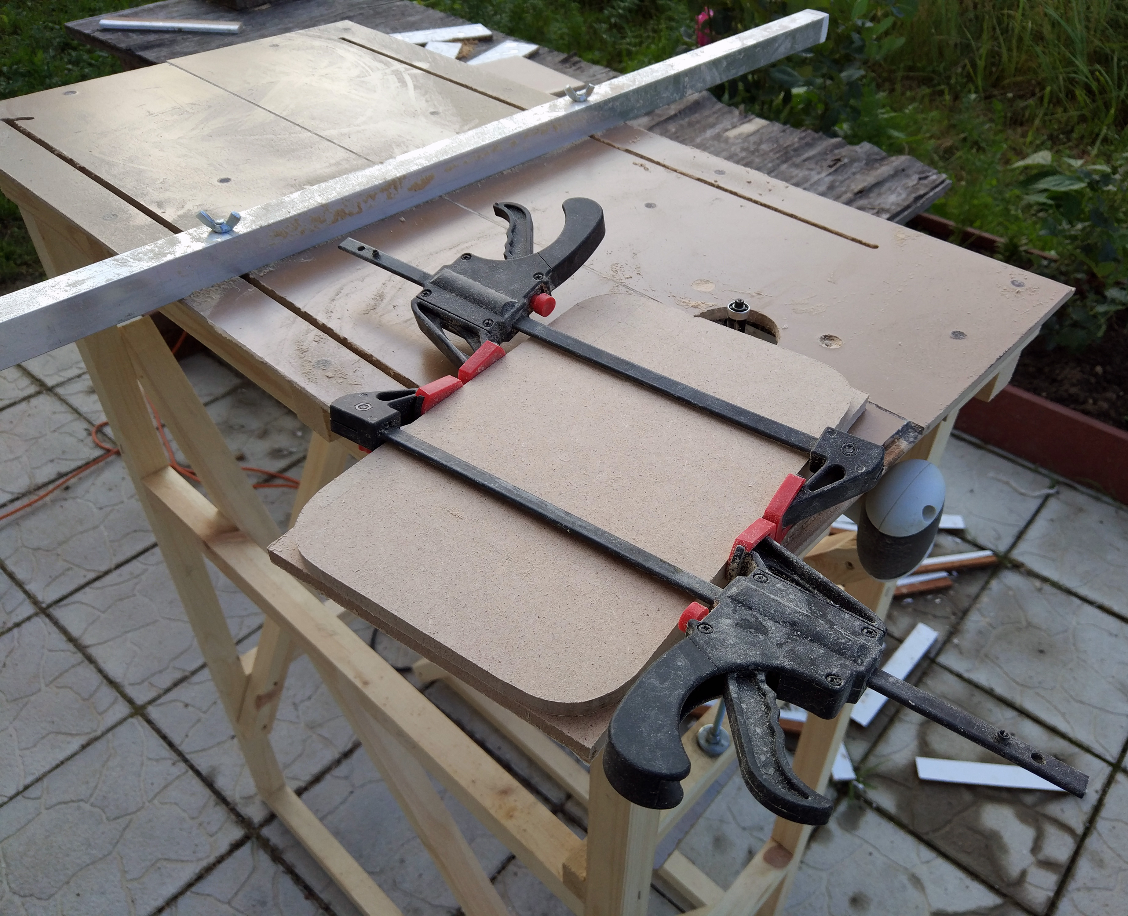
As a guide for milling ideal square aluminum profile 20mm. In the simplest case, it could simply be fastened to the tabletop with clamps from two sides, but this is not comme il faut . It is much better to make it moveable along the table along special guides and fixed with wing screws at the ends. To this end, grooves are milled parallel to the long face at a short distance from the edge. Since all the lamellae are even, the grooves are absolutely parallel, the aluminum profile moves freely along them. To strengthen the clamp, you can use the washer under the screw head (below).
As a guide for milling ideal square aluminum profile 20mm. In the simplest case, it could simply be fastened to the tabletop with clamps from two sides, but this is not comme il faut . It is much better to make it moveable along the table along special guides and fixed with wing screws at the ends. To this end, grooves are milled parallel to the long face at a short distance from the edge. Since all the lamellae are even, the grooves are absolutely parallel, the aluminum profile moves freely along them. To strengthen the clamp, you can use the washer under the screw head (below).
But fotochki process drove
Cutting blanks:
Milling table in action: milling corners by pattern:
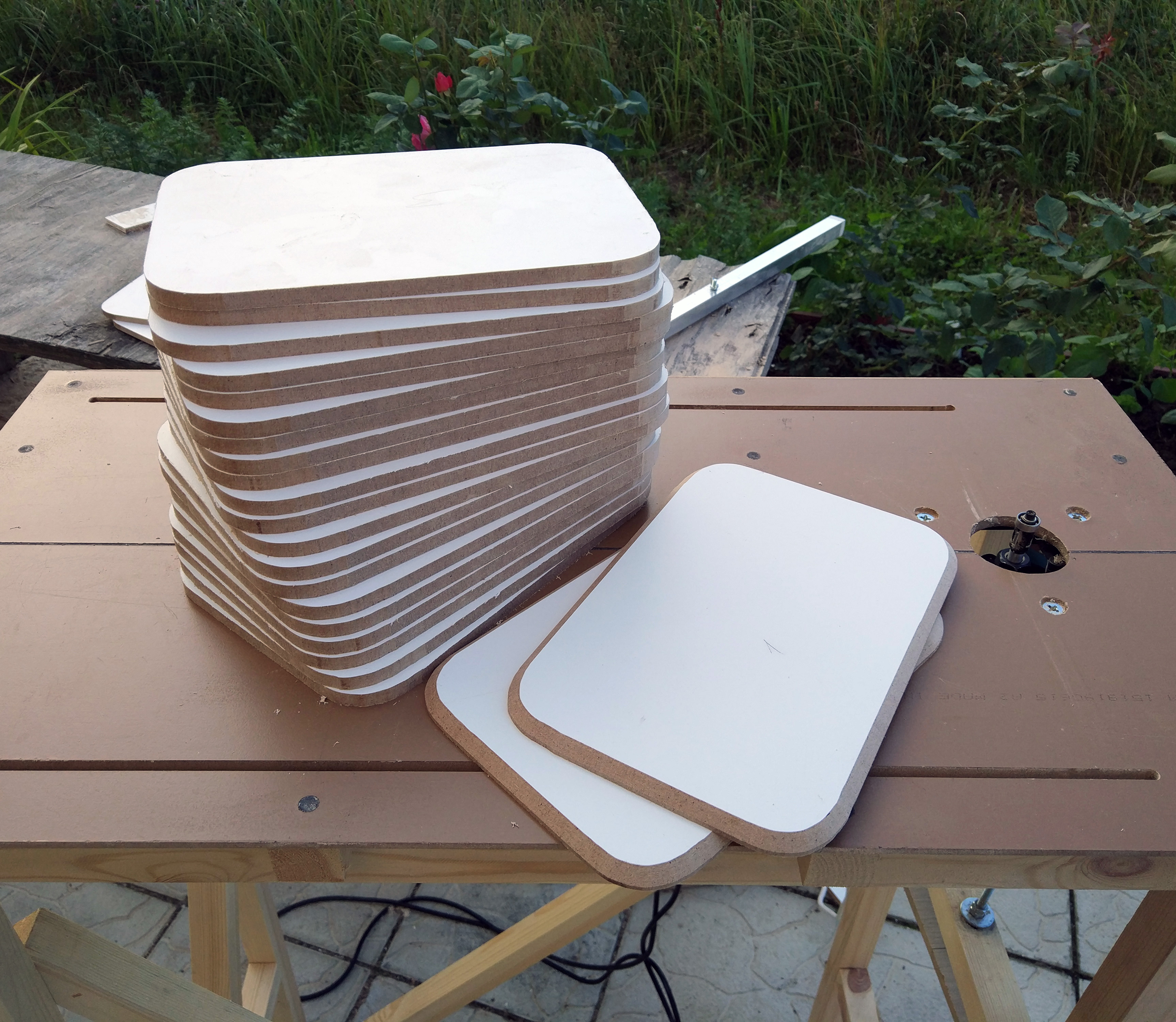
All items after milling. Future covers are separate.
There must be a photo of drunk holes in the layers, but Johnny has already made the installation .
Column housing before grinding:
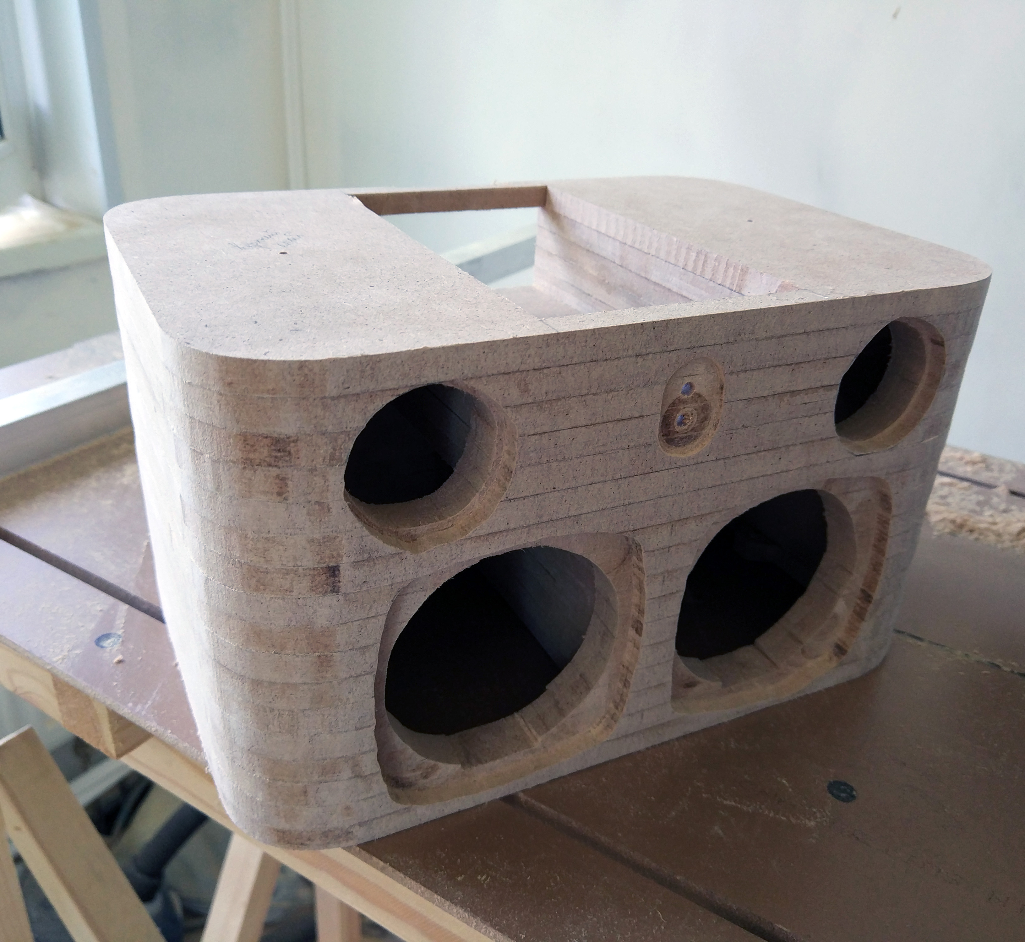
At the end, the body was painted black so that the black speakers did not stand out on it with dark spots after being coated with decorative material.
Milling table in action: milling corners by pattern:
All items after milling. Future covers are separate.
There must be a photo of drunk holes in the layers, but Johnny has already made the installation .
Column housing before grinding:
At the end, the body was painted black so that the black speakers did not stand out on it with dark spots after being coated with decorative material.
And, actually, this is how it looks in the assembled state:
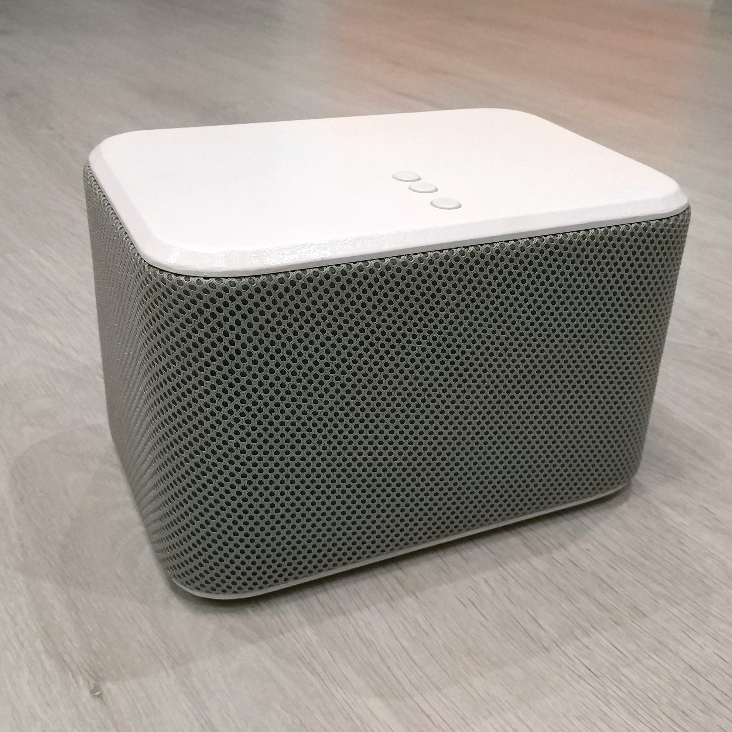
And behind:

The acoustic fabric is glued on the outside, and the white plugs covering its joint and electronics compartment are trimming the 40x25 cable channel. The top and bottom covers are painted with white enamel from a can of 5 layers (I regret very much that I didn’t choose acrylic paint - the enamel smelled badly, dried for a long time, and now actively collects dust and prints).
Filling
The speakers moved to the new building from the old one. There are no complaints against them. These are all the same pair of midbass and a pair of tweeters connected to the amplifier through crossovers .
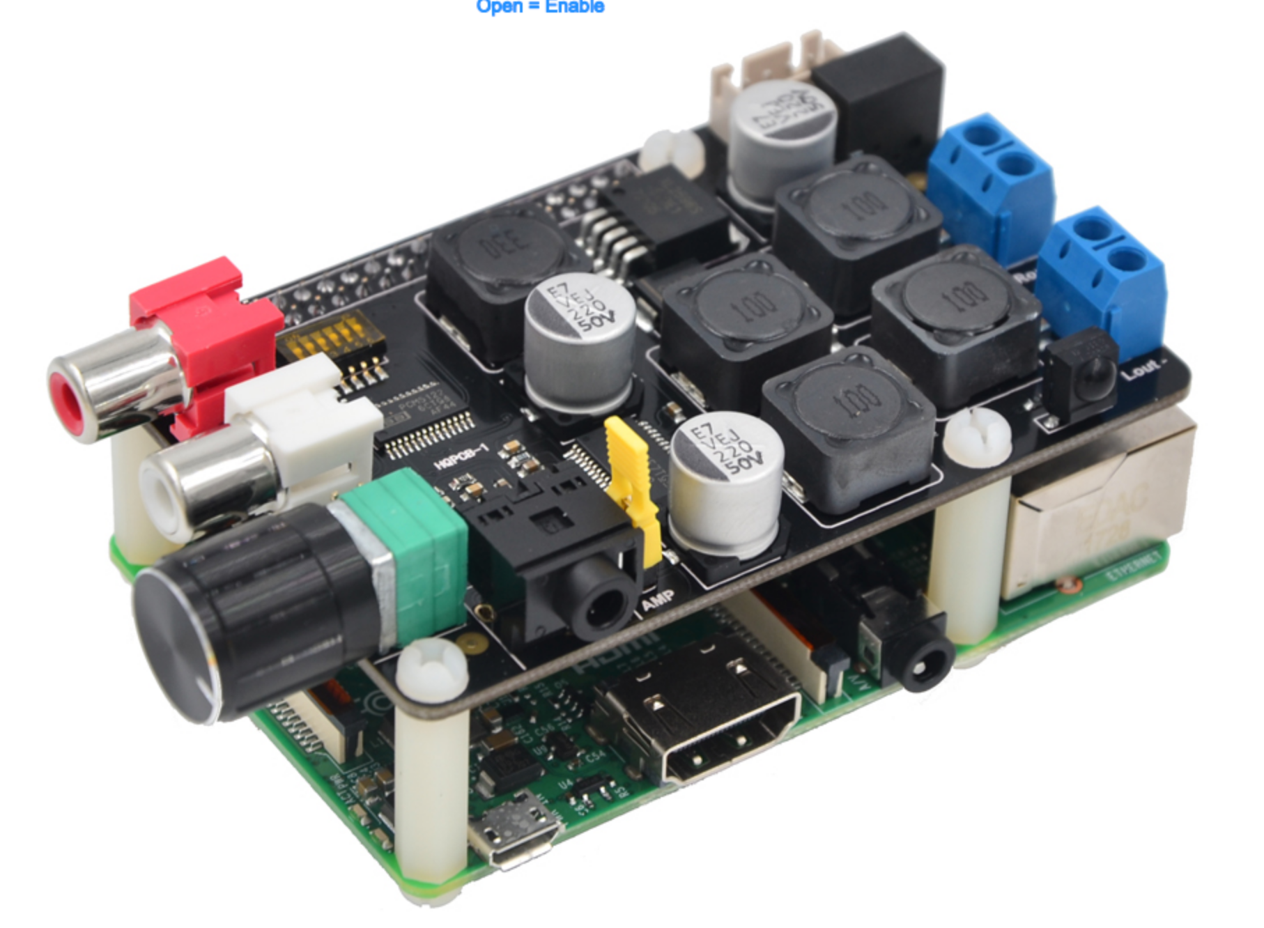
Now for the amp. Since we refuse to use the analog “twist” of the Suptronics X400 board , then you can, as an option, just hide it in the bowels of the case. But the board is large, and because of its size, a couple of problems have appeared that have forced me to look for a replacement for it.
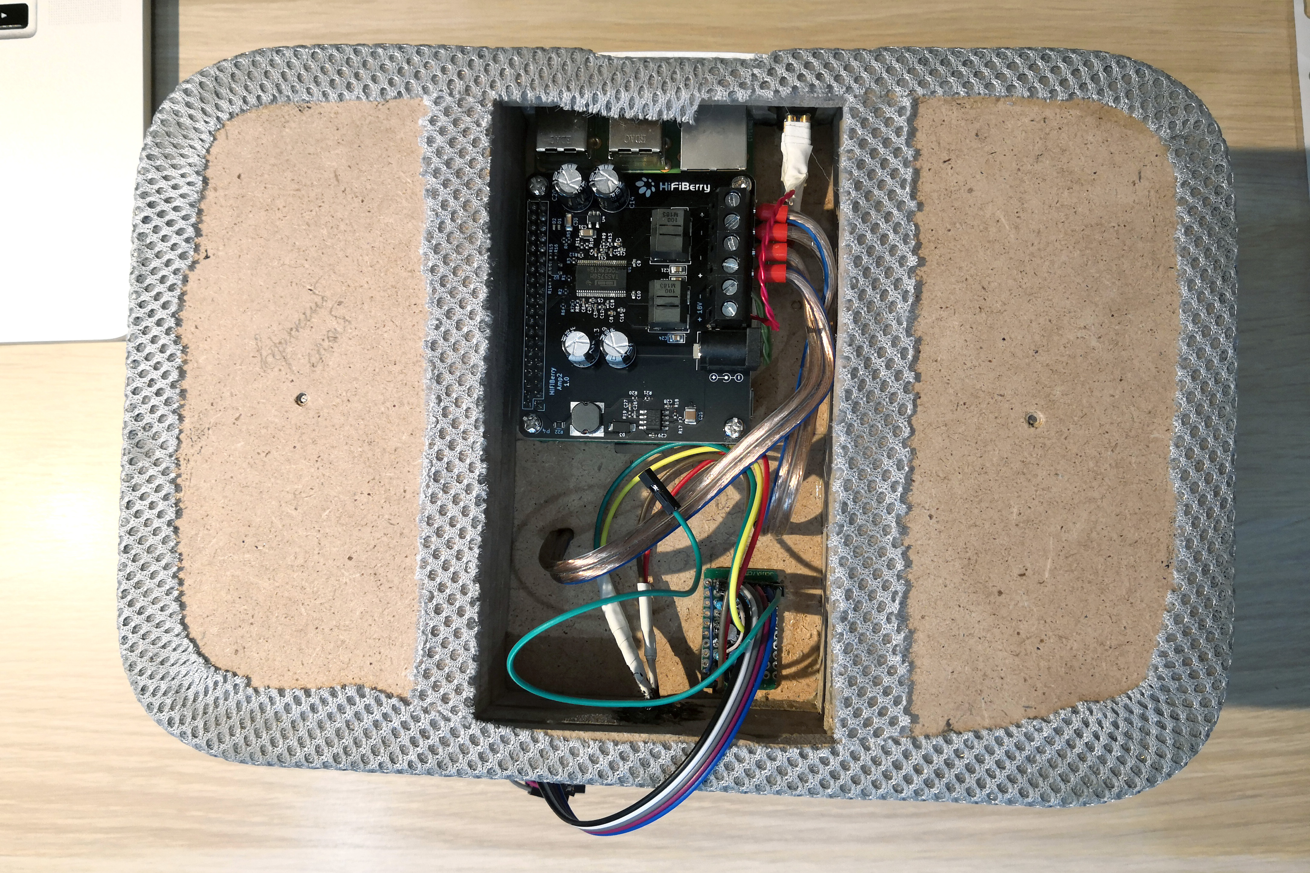
Thanks to IgorKKK , for making me understand Hifiberry products. Once upon a time I thought that their AMP + is only an audio amplifier that should be hung over their DAC + DAC . But AMP + is an all-in-one board, and it could well have replaced the X400, only its performance is worse. But her descendant - AMP2 - with all the characteristics of OK. It is more compact than the X400, and its clamps are moved to a more convenient for mounting side.
For comparison, the sizes of X400 and AMP2 assembled with Raspberry Pi 3
Suptronics X400:
HIFiberry AMP2:
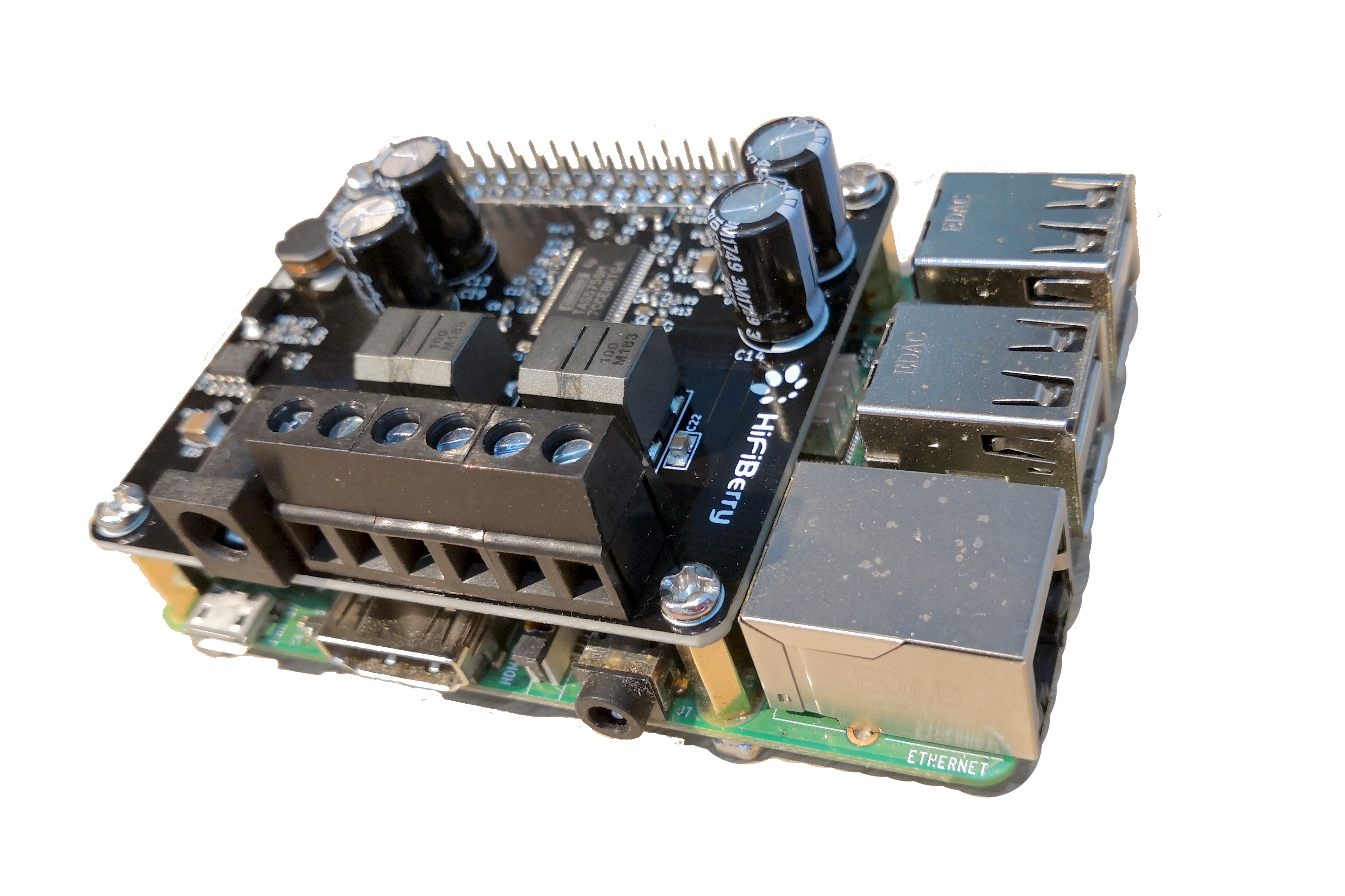
HIFiberry AMP2:
By the way, AMP2 on Aliexpress is not for sale, I ordered it directly from the manufacturer (I highly recommend - an order from Switzerland reached me in just 6 days). But AMP + is quite a buyable for AE.
Component location inside the case
Above - "Malinka", amp and control board:
Below are the speakers and crossovers:
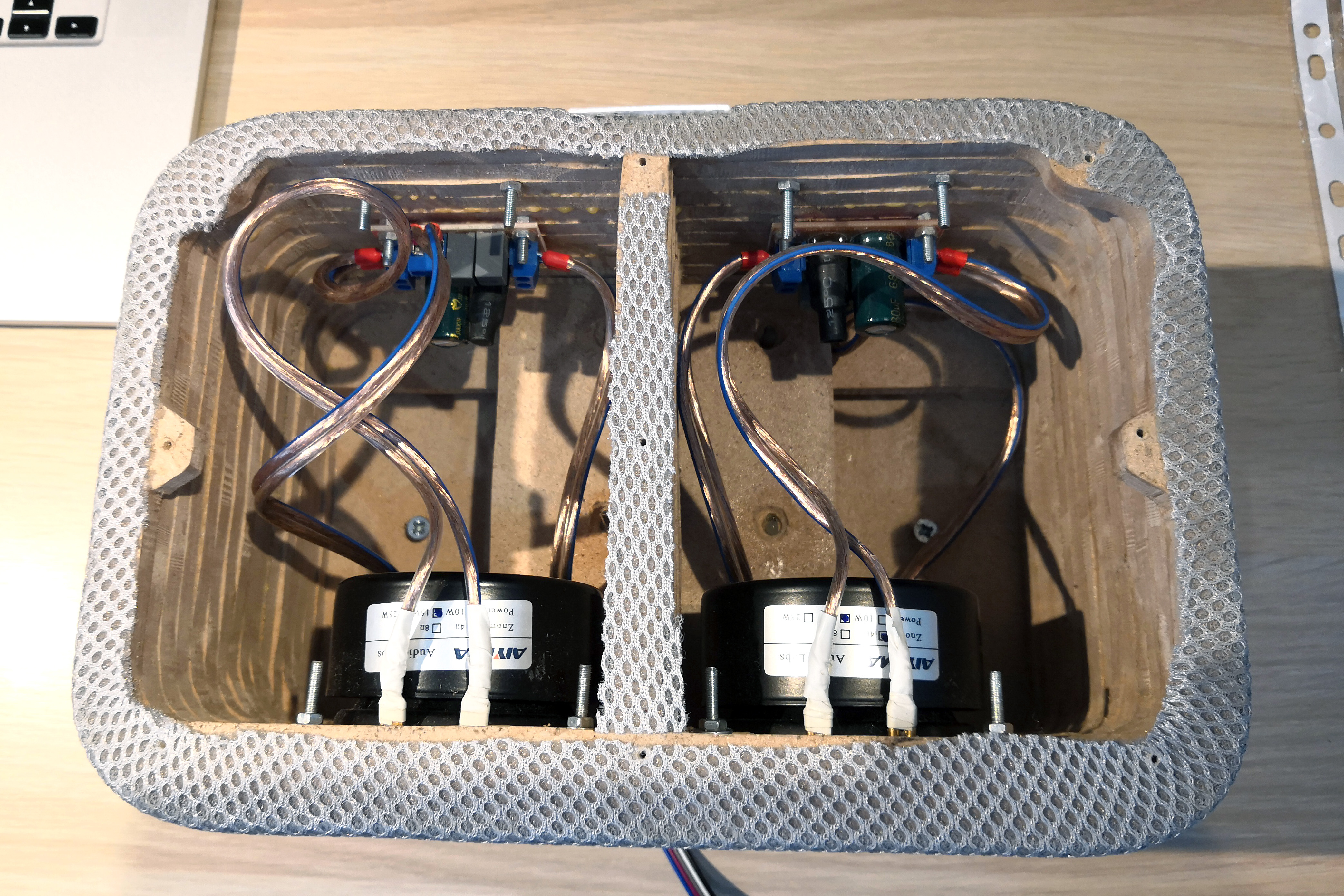
Below are the speakers and crossovers:
Controls
In the previous version, one small board with a button and an LED controlled the playback control. Now the board had to be divided. The first board - with the “play / pause”, “volume -” and “volume +” buttons - is located under the top cover, the second one - which controls the flashing of the LEDs - in the compartment with the “raspberry”.
Circuit board for particularly inquisitive minds
Physical boards are divided by a gray line.

A few comments on the scheme.
On the right, everything is trivial - three buttons with three pairs of protective resistors that protect the input pins from burning out.
Left more interesting. Immediately catches the eye is the inclusion of a blue LED2. The principle of its work is simple, but not obvious. It uses the fact that all common GPIO pins by default work as input. When the power is turned on from the + 3.3V pin, a voltage is applied that drives the current through the limiting resistor R1, the blue LED2 and the pin OUT1 (which is not OUT yet, but IN, therefore you can pass current through it to the input). When the Raspbian is fully loaded, my daemon starts up, which takes the OUT1 pin to output mode and applies + 3.3V (HIGH) to it. The potential difference falling on the section "R1-LED2" becomes equal to 0V, and the LED goes out. So the column signals full readiness for work.
White LED works in three modes:
always on - the speaker plays music;
flashes seldom and smoothly - the column in the pause mode;
flashes often and abruptly - a button is pressed.
The on and off of the white diode is controlled by the pin OUT2, and the smoothness of the flashing - the pin OUT3. When flashing is needed, the logical 1 (HIGH, + 3.3V) is fed to the MOSFET pin Q1 of the OUT3 pin, the transistor opens the “R12-C1-Q1” circuit. And then when installing pin OUT2 to the HIGH level (+ 3.3V), the current starts charging the capacitor C1 and, as it is charged, the LED1 turns on. When the OUT2 pin is set to LOW (0V), the capacitor gradually discharges through the LED, gradually reducing its brightness level to 0. It is easy to calculate that the full charge / discharge time of the capacitor is approximately 3 seconds, the best, in my opinion, blinking.
Finally, software and UX
The web interface has become more functional, more pleasant, and has learned to load the album cover for the current composition. All code is still available to anyone on Github .
Comparison with version 2.0
| It was | It became |
|---|---|
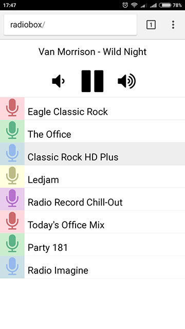 | 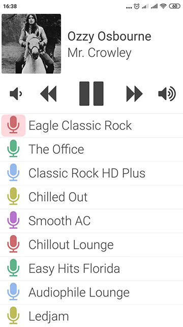 |
In the logic of the physical buttons added processing long press:
play / pause: short press - start / stop playback; long press - switch the station to the next one on the list;
volume: short press - change volume once; long press - continuous volume change.
Well, what's next?
The photo shows that the building was going in the summer, and he had enough time for running in and refinement. At the moment, both appearance and sound quality and usability suit both my home and (most importantly) me. And although so far I see no reason for reworking this body and / or replacing its parts, I don’t intend to stop there. The plans include turning this speaker into a voice assistant, as well as manufacturing a mini-column for a nursery based on the Raspberry Pi Zero in a case printed on a 3D printer. So wait for new articles in the near future!
Source: https://habr.com/ru/post/435128/
All Articles