Non-canon tube amplifier
Good day to all!
Somehow, on a cold, dreary evening, I read an article about a high-quality amplifier class D c Aliexpress . And the thought occurred to me to tell about my DIY-craft. But now they got their hands. Below is a worklog about making the next-how-already-possible tube (and not only) amplifier. The article is replete with frivolity and petrosyanism, but nevertheless you can find a couple of useful schemes here.
Immediately clarify:
')
I repeat: the whole project was started not for the sake of getting a “tube” sound, but because of the special aesthetics of well-made tube amplifiers. It was aesthetics that became the basis for the overwhelming majority of the problems that arose. She also determined the final cost, quite noticeably exceeded the initial budget: piece production (in this case, read prototyping) is always much more expensive than it might seem at first glance. Just right away I want to note that the task was to develop an amplifier from scratch, not reducing everything to the banal “I bought a set on the Internet, I sealed it and put it in a shoe box”. In the end, it’s still a DIY project, there must be a challenge, suffering and a desire to throw everything to hell! However, it is not worth going to extremes either. In theory, everything can be done completely without the use of purchased products, but in this case we need the appropriate tools (read the machines), otherwise the result may, to put it mildly, disappoint.
The only question is the final goal. So, let's begin!
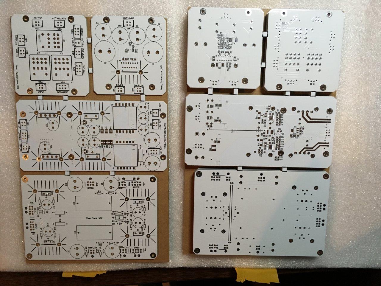
Good planning is a pledge of fewer iterations from “how could I even do such a thing” to “could have been better, but it will come down like that.” The amplifier was originally conceived to replace the standard speakers to the computer. Let's be honest, viewing vidyashek with sweet cats under the rug through a warm tube amplifier, of course, and can complement the picture, but is not rational. Which leads to a completely logical idea to throw an amplifier inside on good old solid-state semiconductors. And by his own mood, Monsieur is free to choose which of the amplifiers to use for listening to Dire Straits, and which for 2Pac. As a result, the circuitry has become somewhat more complicated, but we remember about the challenge, the tests, and all that. The result is 4 printed circuit boards: power supply, tube amplifier, solid-state amplifier and switching board. It seems simple, go further.
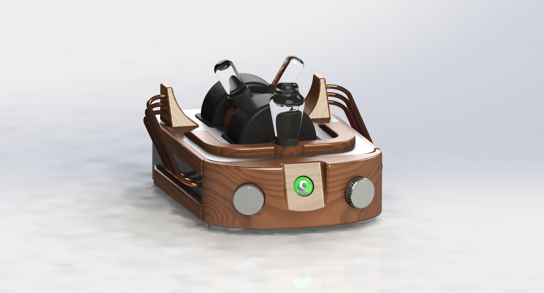
Actually for what all the fuss. My pictorial talents are limited to conditionally straight lines exclusively on squared paper. But there is an engineering education, so having armed with CAD and great patience, slowly and with a creak I visualized what I would like to get in the end. And yes, do not be surprised that first comes the body design, not the circuitry, as usual.
A little about the case itself and the "classic" type of tube amplifier. I never understood the passion to put all the electronics out. Lamps, yes, they are beautiful, hot and putting them outside (even sacrificing a little noise immunity) is not such a bad idea, but screwing huge transformers with a W-shaped core ON the top case cover is a rather dubious decision. Some go even further: and, in addition to all of the above, they put a capacitor bank on top! The finish! It seems that you are not looking at the finished device, but at some kind of breadboard model. Although the taste and color of all the markers are different ...
I settled on using anodized and brushed aluminum enclosures with mahogany (jarrah) decorative overlays. Also, to reduce the size, it was decided to use toroidal transformers. The metal base of the case, the knobs of switches, legs - purchased from Aliexpress, the rest was planned to make on their own. Almost every detail was drawn, after which everything beautifully fell into place ...
And then they sent the case. Needless to say, the dimensions given by the Chinese in the documentation have a rather mediocre relation to the real device. Always wondered: "in China, everything is done by sight?". What is the problem to attach the correct drawings, on which you produce the part? I understand, if they hadn’t been put at all, so no, they were there, but not the right ones! Apparently protection from competitors.
When the approximate dimensions of the case became clear, the turn came in circuitry. Why in this sequence? For the sake of compactness. With a weight of more than 10 kg, dimensions are 40x30x20 cm (with all the decorative elements). Inside it is pretty plump (see photo below). As a result, the size of the components on the boards, as well as the dimensions of the boards themselves, are of great importance. The dimensions of the printed circuit boards, the height of the components, the placement of the elements, everything was selected, drawn in 3D and checked on the assembly. If the details relate to each other - go back two steps back, and so on until victory. The first couple of times it is even entertaining: here I am so well done, checked everything, avoided problems. Somewhere after the third time, the thought comes to drink to the health of developers of parametric CAD systems. I strongly recommend to anyone who has not yet learned the basics of any of the systems, and not to neglect the stage of modeling, even for home crafts. From the large one that I discovered: it turned out that the 90 W mains transformer, which initially stood perfectly, did not fit in the case (hello to Chinese drawings). I had to replace it with two 60 W each (these are the ones inside on the side walls).
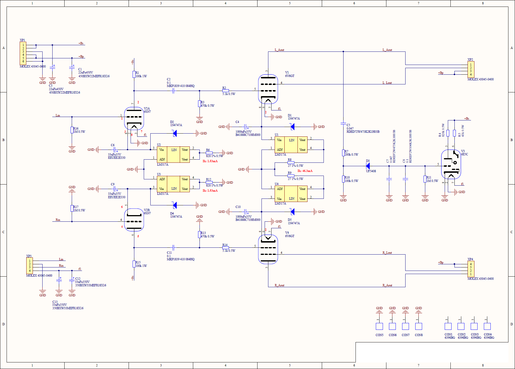
I never had cases with tube technology, and that says it all. Technically, I can draw analogies with transistors and, in general, everything is quite simple, but not without nuances. After spending a few days searching in the open spaces of the network, I settled on a variant using single-ended output stages on 6V6GT lamps. If someone is very interested in comparing different variants of the output stages, as well as in general, different classes of amplifiers, I advise you to read here . I chose what I chose and do not want to overload the text with unnecessary information.
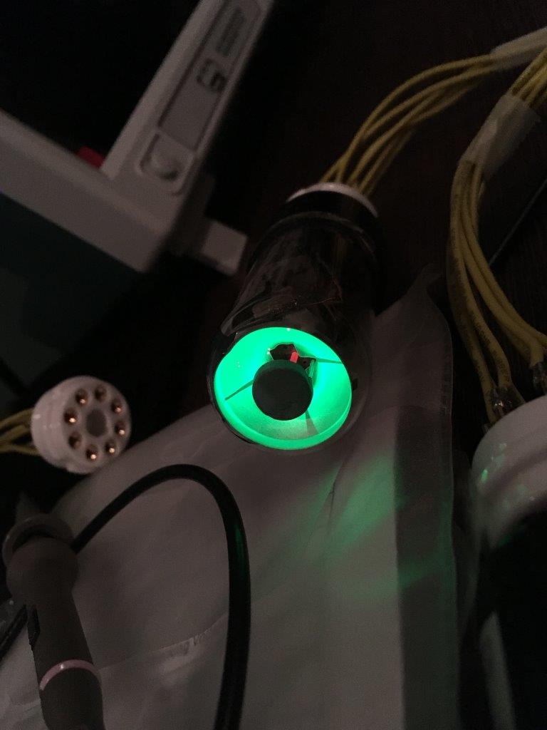
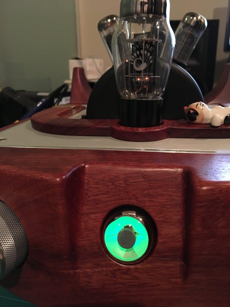
But I can’t help but clarify that Class A single-ended amplifiers have a special warmth and depth of sound, especially on medium often ... tfu, I almost did not believe it! But seriously: in addition to the absence of “step” type distortion at the output stage, they are simply warm. No, they are really very warm, because the efficiency of class A amplifiers does not exceed 10-15%, the rest is spent on heating the room. The estimated power of my amplifier is about 4.5 watts. I used this scheme as a basis, but made some corrections. And, in addition to the lampiness, of course, the luminous indicator of the “magic eye” type. Looks very nice.
From this moment begins the selective heresy, according to the ideas of the true witnesses of the tube sound, I strongly recommend the adherents of this faith to scroll through the text and just pozalipat on the result photo. I warned!
Let's start with the fact that I do not like the classic approach to the construction of tube amplifiers, which involves the use of exclusively passive components (resistors, capacitors, transformers), with the exception of the lamps themselves. Solid-state semiconductor devices have a great advantage (one of) in front of lamps - a much smaller variation of characteristics. Two lamps of the same name, even issued in the same batch, can vary significantly. Because of this, it can often be seen that the output stage lamps are sold in matched pairs with similar characteristics. But where is the guarantee that after warming up they will remain the same? And after a certain operating time by the hour? Too many uncertainties. At the same time, semiconductor devices can be used to level the spread of parameters. For example, instead of the standard resistor that sets the cathode current, you can use a current source on the LM317A. At the same time, this will not affect the sound path, but the current will not depend on the lamp parameters. On the Internet, you can find options for such solutions, so that my particular originality is no different.
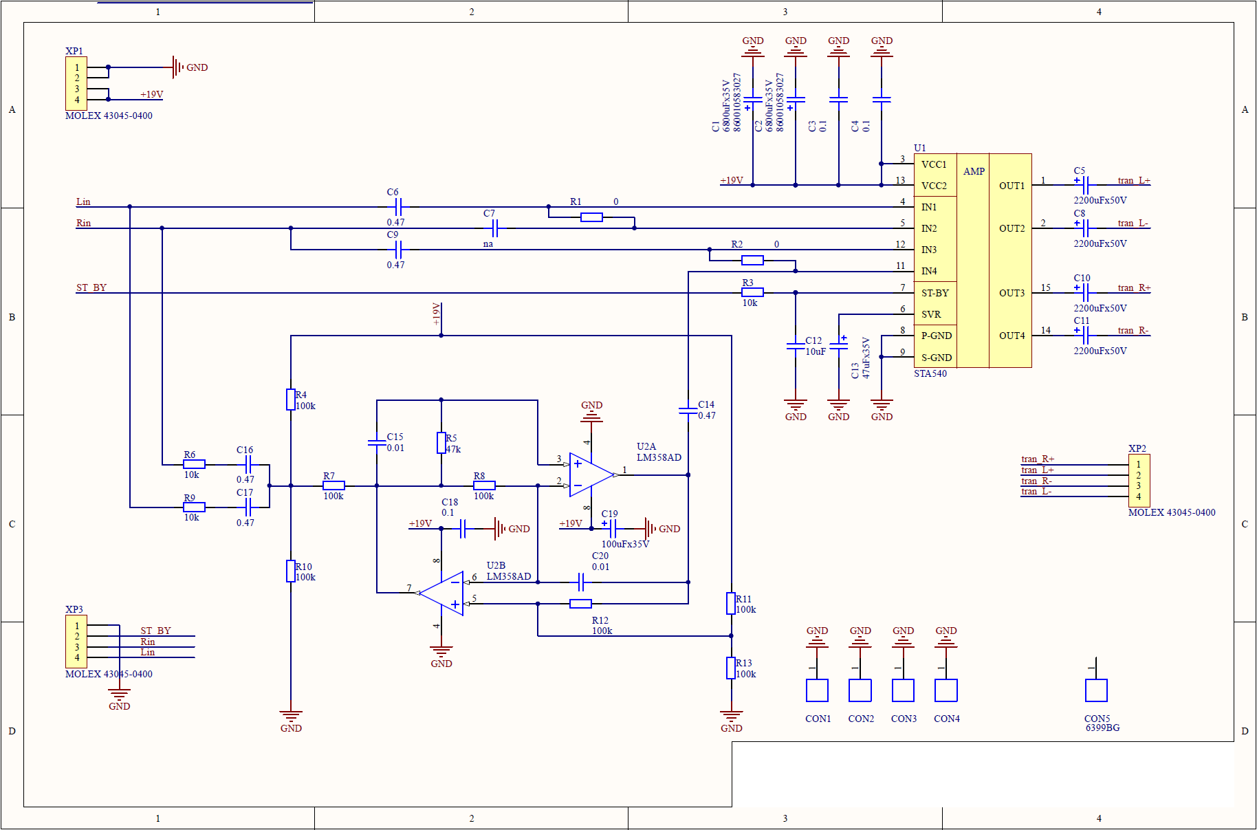
The solid state amplifier is even less remarkable: the standard STA540 chip with minimal strapping. AB class amplifier, for everyday use in conjunction with a computer - the most it. Additionally, it is possible to solder an active filter to the board and use it as a 2.1 system, i.e. with a subwoofer. In this embodiment, is not used.
Finally, the most fun - the power source. Here was a complete hardcore.
Going contrary to dogma, I decided not only not to use the cenoteurs loved by all lampoviki, but also in principle to refuse the linear power source! Pulsed power sources are better, both in terms of efficiency and in terms of size. Then the design went and did the curve track. The choice of the PWM controller chip and the flyback transformer was chosen according to the principle “for free to try, why not?”. The fact is that the controller and transformers specially designed for it can be ordered as samples for free (with registration, but without SMS!). This is not the best option, because there are more standard, proven controllers, and therefore a bunch of time-tested schemes. Below is a diagram of power sources for lamp (+300 V, +285 V, +6 V) and solid-state (+18 V) amplifiers.

The voltage from the step-down network transformers is rectified, and then fed to the pulse converters. An experienced power source developer may ask: why such perversions? Indeed, one could immediately rectify the mains voltage and put it on the converters, but I wanted to make a galvanic isolation from the network. In the above version of the scheme there are no inductive filters on the outputs of the pulse sources (added by volumetric wiring). In the next version, the jamb will be fixed.
Looking ahead, I will say that setting up the power supply was the most problematic of all debugging work. In part, this was due to the fact that the last time he was seriously engaged in circuitry about 6 years ago. But in the end, partly after dancing with a tambourine, partly, after asking stupid questions on the thematic forums, I found a solution to the problems and everything started!
Printed circuit boards ordered from the Chinese on FirstPCB. Quality is acceptable: silk-screen printing has a different thickness, the holes are slightly offset from the center of the contact pads. In general - not bad, considering the cost.
The minimum order is 5 pcs, so I now have several more of them ...
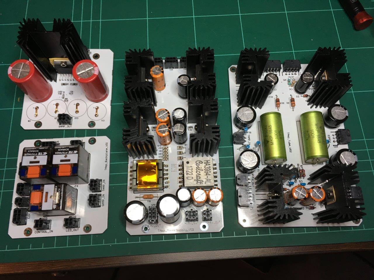
Fees after unpacking:
and soldered:
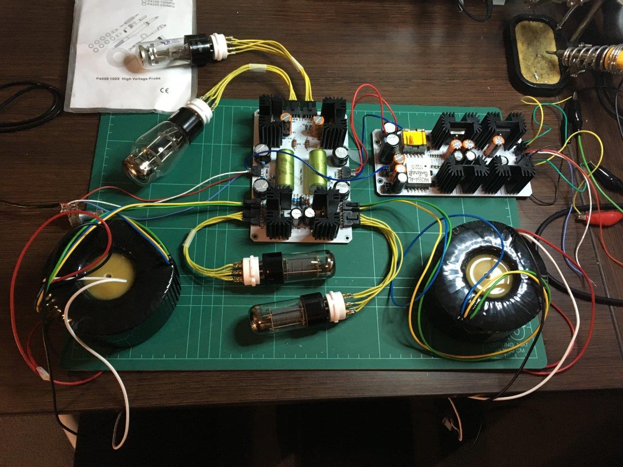
Test amplifier without body:
So where do without the magic eye:
Next, the case. The fact is that in our area, for reasons unknown to me, it is very difficult to order the processing of a piece of wood on a 5-axis CNC machine. They ask either fabulously expensive, or do not do it at all. And this despite the fact that, being a bit in the subject, I designed with minimization of complexity. The Chinese did not help either: having sent a request to 8 companies, I received a positive answer only from two. The rest of the parties less than 10 pieces are not interested, although their sites and talk about the services of prototyping. But the remaining two, too, decided not to limit themselves in price, and besides, they asked for photos and a complete drawing of the device! I wonder why they need it ...
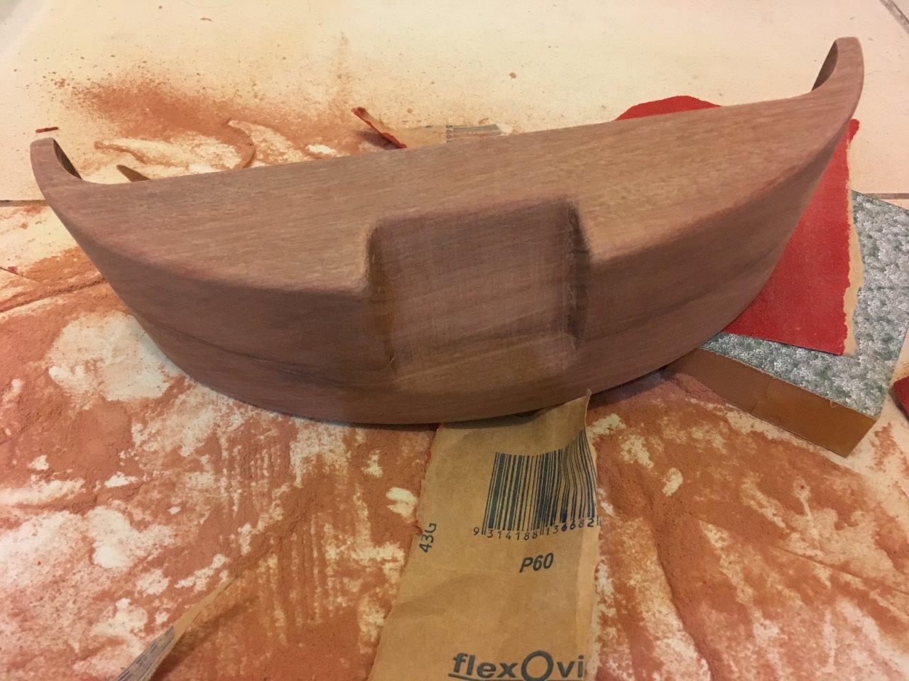
As a result, we had to simplify parts to almost 2.5D and turn them on a local CNC machine. On the one hand, it turned out, relative to the rest, not expensive. On the other hand, if we add to this all those square kilometers of coarse sandpaper that I had to lime, governing what these guys did ... Seriously, the feeling is that they are not familiar with the technology in principle and used standard modes for particleboard, from which they grind out 99% of their orders. But I'm not greedy, I additionally gave them a weighty piece of material for the selection of parameters!

More sandpaper god sandpaper:
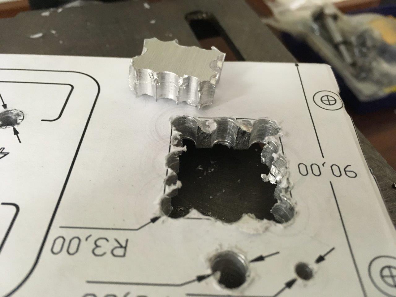
Special thanks to them for having promised at first to make holes in aluminum parts, and then stated that they had never done this before and are afraid to break the machine. Iron logic, even arguing is useless. As a result, the project was transformed from a non-stressed screwdriver assembly of ordered parts into a hardcore DIY, because working with metal, even with soft aluminum, in a small apartment makes you experience existential horror. At first. And then you reach the stage of adoption, you take a hand drill, a hacksaw for metal and move steadily towards your intended goal.
Next, a few pictures with the stages of assembly for fans of gyporno:
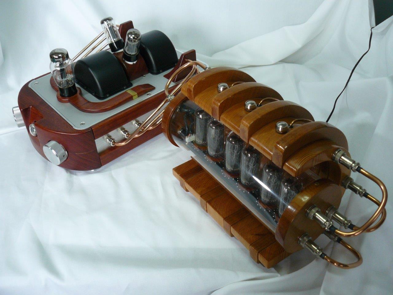
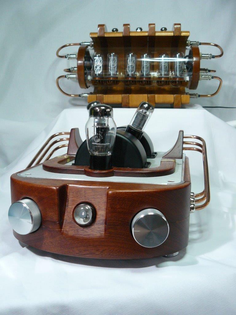
Below is the final photo session of the fully assembled device. There is also a clock on the gas-discharge indicators, which in fact squares the warmth and luminosity of the whole scene!
On the whole project, from idea to implementation, it took about six months. Several analyzes and fees of the amplifier were left behind the frame in order to make changes and improvements, but this can be done endlessly. In general, the result pleased. As planned, in most cases a solid-state amplifier is used and only occasionally a tube is launched, mostly to compare. Nevertheless, the main goal - to revive his old hobby and dig deeper in electronics, was fully achieved! Write in the comments your questions and comments.
Have a great weekend everyone!
Somehow, on a cold, dreary evening, I read an article about a high-quality amplifier class D c Aliexpress . And the thought occurred to me to tell about my DIY-craft. But now they got their hands. Below is a worklog about making the next-how-already-possible tube (and not only) amplifier. The article is replete with frivolity and petrosyanism, but nevertheless you can find a couple of useful schemes here.
Warnings:
- CAUTION traffic! A lot of pictures.
- CAUTION! The circuits presented use life-threatening voltages. Reproducing the above schemes, you do this at your own peril and risk. The author is not responsible for the consequences resulting from the duplication of both the entire device and its individual parts.
Immediately clarify:
')
- The amplifier is not a Hi-End or Hi-Fi, because in its production not a single gram of powder paint was used!
- I am not an adherent of the confession of spiritual, thermal tube sound. But the lamps are so cool glow ...
- To the possible questions of the class “But why bother at all?”, The answer is “Because a hobby.
I repeat: the whole project was started not for the sake of getting a “tube” sound, but because of the special aesthetics of well-made tube amplifiers. It was aesthetics that became the basis for the overwhelming majority of the problems that arose. She also determined the final cost, quite noticeably exceeded the initial budget: piece production (in this case, read prototyping) is always much more expensive than it might seem at first glance. Just right away I want to note that the task was to develop an amplifier from scratch, not reducing everything to the banal “I bought a set on the Internet, I sealed it and put it in a shoe box”. In the end, it’s still a DIY project, there must be a challenge, suffering and a desire to throw everything to hell! However, it is not worth going to extremes either. In theory, everything can be done completely without the use of purchased products, but in this case we need the appropriate tools (read the machines), otherwise the result may, to put it mildly, disappoint.
The only question is the final goal. So, let's begin!
A play in four acts. Heroic Epos
Act the first. Planned
Good planning is a pledge of fewer iterations from “how could I even do such a thing” to “could have been better, but it will come down like that.” The amplifier was originally conceived to replace the standard speakers to the computer. Let's be honest, viewing vidyashek with sweet cats under the rug through a warm tube amplifier, of course, and can complement the picture, but is not rational. Which leads to a completely logical idea to throw an amplifier inside on good old solid-state semiconductors. And by his own mood, Monsieur is free to choose which of the amplifiers to use for listening to Dire Straits, and which for 2Pac. As a result, the circuitry has become somewhat more complicated, but we remember about the challenge, the tests, and all that. The result is 4 printed circuit boards: power supply, tube amplifier, solid-state amplifier and switching board. It seems simple, go further.
Act of the second. Design
Actually for what all the fuss. My pictorial talents are limited to conditionally straight lines exclusively on squared paper. But there is an engineering education, so having armed with CAD and great patience, slowly and with a creak I visualized what I would like to get in the end. And yes, do not be surprised that first comes the body design, not the circuitry, as usual.
A little about the case itself and the "classic" type of tube amplifier. I never understood the passion to put all the electronics out. Lamps, yes, they are beautiful, hot and putting them outside (even sacrificing a little noise immunity) is not such a bad idea, but screwing huge transformers with a W-shaped core ON the top case cover is a rather dubious decision. Some go even further: and, in addition to all of the above, they put a capacitor bank on top! The finish! It seems that you are not looking at the finished device, but at some kind of breadboard model. Although the taste and color of all the markers are different ...
I settled on using anodized and brushed aluminum enclosures with mahogany (jarrah) decorative overlays. Also, to reduce the size, it was decided to use toroidal transformers. The metal base of the case, the knobs of switches, legs - purchased from Aliexpress, the rest was planned to make on their own. Almost every detail was drawn, after which everything beautifully fell into place ...
And then they sent the case. Needless to say, the dimensions given by the Chinese in the documentation have a rather mediocre relation to the real device. Always wondered: "in China, everything is done by sight?". What is the problem to attach the correct drawings, on which you produce the part? I understand, if they hadn’t been put at all, so no, they were there, but not the right ones! Apparently protection from competitors.
When the approximate dimensions of the case became clear, the turn came in circuitry. Why in this sequence? For the sake of compactness. With a weight of more than 10 kg, dimensions are 40x30x20 cm (with all the decorative elements). Inside it is pretty plump (see photo below). As a result, the size of the components on the boards, as well as the dimensions of the boards themselves, are of great importance. The dimensions of the printed circuit boards, the height of the components, the placement of the elements, everything was selected, drawn in 3D and checked on the assembly. If the details relate to each other - go back two steps back, and so on until victory. The first couple of times it is even entertaining: here I am so well done, checked everything, avoided problems. Somewhere after the third time, the thought comes to drink to the health of developers of parametric CAD systems. I strongly recommend to anyone who has not yet learned the basics of any of the systems, and not to neglect the stage of modeling, even for home crafts. From the large one that I discovered: it turned out that the 90 W mains transformer, which initially stood perfectly, did not fit in the case (hello to Chinese drawings). I had to replace it with two 60 W each (these are the ones inside on the side walls).
Act third. Circuitry
I never had cases with tube technology, and that says it all. Technically, I can draw analogies with transistors and, in general, everything is quite simple, but not without nuances. After spending a few days searching in the open spaces of the network, I settled on a variant using single-ended output stages on 6V6GT lamps. If someone is very interested in comparing different variants of the output stages, as well as in general, different classes of amplifiers, I advise you to read here . I chose what I chose and do not want to overload the text with unnecessary information.
But I can’t help but clarify that Class A single-ended amplifiers have a special warmth and depth of sound, especially on medium often ... tfu, I almost did not believe it! But seriously: in addition to the absence of “step” type distortion at the output stage, they are simply warm. No, they are really very warm, because the efficiency of class A amplifiers does not exceed 10-15%, the rest is spent on heating the room. The estimated power of my amplifier is about 4.5 watts. I used this scheme as a basis, but made some corrections. And, in addition to the lampiness, of course, the luminous indicator of the “magic eye” type. Looks very nice.
From this moment begins the selective heresy, according to the ideas of the true witnesses of the tube sound, I strongly recommend the adherents of this faith to scroll through the text and just pozalipat on the result photo. I warned!
Let's start with the fact that I do not like the classic approach to the construction of tube amplifiers, which involves the use of exclusively passive components (resistors, capacitors, transformers), with the exception of the lamps themselves. Solid-state semiconductor devices have a great advantage (one of) in front of lamps - a much smaller variation of characteristics. Two lamps of the same name, even issued in the same batch, can vary significantly. Because of this, it can often be seen that the output stage lamps are sold in matched pairs with similar characteristics. But where is the guarantee that after warming up they will remain the same? And after a certain operating time by the hour? Too many uncertainties. At the same time, semiconductor devices can be used to level the spread of parameters. For example, instead of the standard resistor that sets the cathode current, you can use a current source on the LM317A. At the same time, this will not affect the sound path, but the current will not depend on the lamp parameters. On the Internet, you can find options for such solutions, so that my particular originality is no different.
The solid state amplifier is even less remarkable: the standard STA540 chip with minimal strapping. AB class amplifier, for everyday use in conjunction with a computer - the most it. Additionally, it is possible to solder an active filter to the board and use it as a 2.1 system, i.e. with a subwoofer. In this embodiment, is not used.
Finally, the most fun - the power source. Here was a complete hardcore.
Going contrary to dogma, I decided not only not to use the cenoteurs loved by all lampoviki, but also in principle to refuse the linear power source! Pulsed power sources are better, both in terms of efficiency and in terms of size. Then the design went and did the curve track. The choice of the PWM controller chip and the flyback transformer was chosen according to the principle “for free to try, why not?”. The fact is that the controller and transformers specially designed for it can be ordered as samples for free (with registration, but without SMS!). This is not the best option, because there are more standard, proven controllers, and therefore a bunch of time-tested schemes. Below is a diagram of power sources for lamp (+300 V, +285 V, +6 V) and solid-state (+18 V) amplifiers.
The voltage from the step-down network transformers is rectified, and then fed to the pulse converters. An experienced power source developer may ask: why such perversions? Indeed, one could immediately rectify the mains voltage and put it on the converters, but I wanted to make a galvanic isolation from the network. In the above version of the scheme there are no inductive filters on the outputs of the pulse sources (added by volumetric wiring). In the next version, the jamb will be fixed.
Looking ahead, I will say that setting up the power supply was the most problematic of all debugging work. In part, this was due to the fact that the last time he was seriously engaged in circuitry about 6 years ago. But in the end, partly after dancing with a tambourine, partly, after asking stupid questions on the thematic forums, I found a solution to the problems and everything started!
Act of the fourth, the last. Assembly
Printed circuit boards ordered from the Chinese on FirstPCB. Quality is acceptable: silk-screen printing has a different thickness, the holes are slightly offset from the center of the contact pads. In general - not bad, considering the cost.
The minimum order is 5 pcs, so I now have several more of them ...
Fees after unpacking:
and soldered:
Test amplifier without body:
So where do without the magic eye:
Next, the case. The fact is that in our area, for reasons unknown to me, it is very difficult to order the processing of a piece of wood on a 5-axis CNC machine. They ask either fabulously expensive, or do not do it at all. And this despite the fact that, being a bit in the subject, I designed with minimization of complexity. The Chinese did not help either: having sent a request to 8 companies, I received a positive answer only from two. The rest of the parties less than 10 pieces are not interested, although their sites and talk about the services of prototyping. But the remaining two, too, decided not to limit themselves in price, and besides, they asked for photos and a complete drawing of the device! I wonder why they need it ...
As a result, we had to simplify parts to almost 2.5D and turn them on a local CNC machine. On the one hand, it turned out, relative to the rest, not expensive. On the other hand, if we add to this all those square kilometers of coarse sandpaper that I had to lime, governing what these guys did ... Seriously, the feeling is that they are not familiar with the technology in principle and used standard modes for particleboard, from which they grind out 99% of their orders. But I'm not greedy, I additionally gave them a weighty piece of material for the selection of parameters!
More sandpaper god sandpaper:
Special thanks to them for having promised at first to make holes in aluminum parts, and then stated that they had never done this before and are afraid to break the machine. Iron logic, even arguing is useless. As a result, the project was transformed from a non-stressed screwdriver assembly of ordered parts into a hardcore DIY, because working with metal, even with soft aluminum, in a small apartment makes you experience existential horror. At first. And then you reach the stage of adoption, you take a hand drill, a hacksaw for metal and move steadily towards your intended goal.
Next, a few pictures with the stages of assembly for fans of gyporno:
Fotochki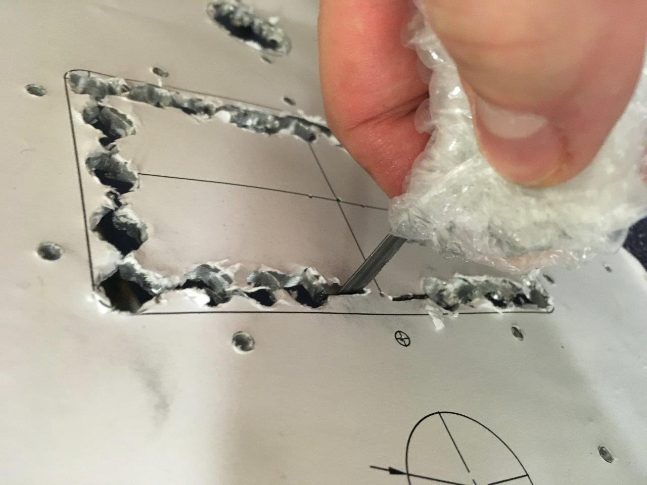
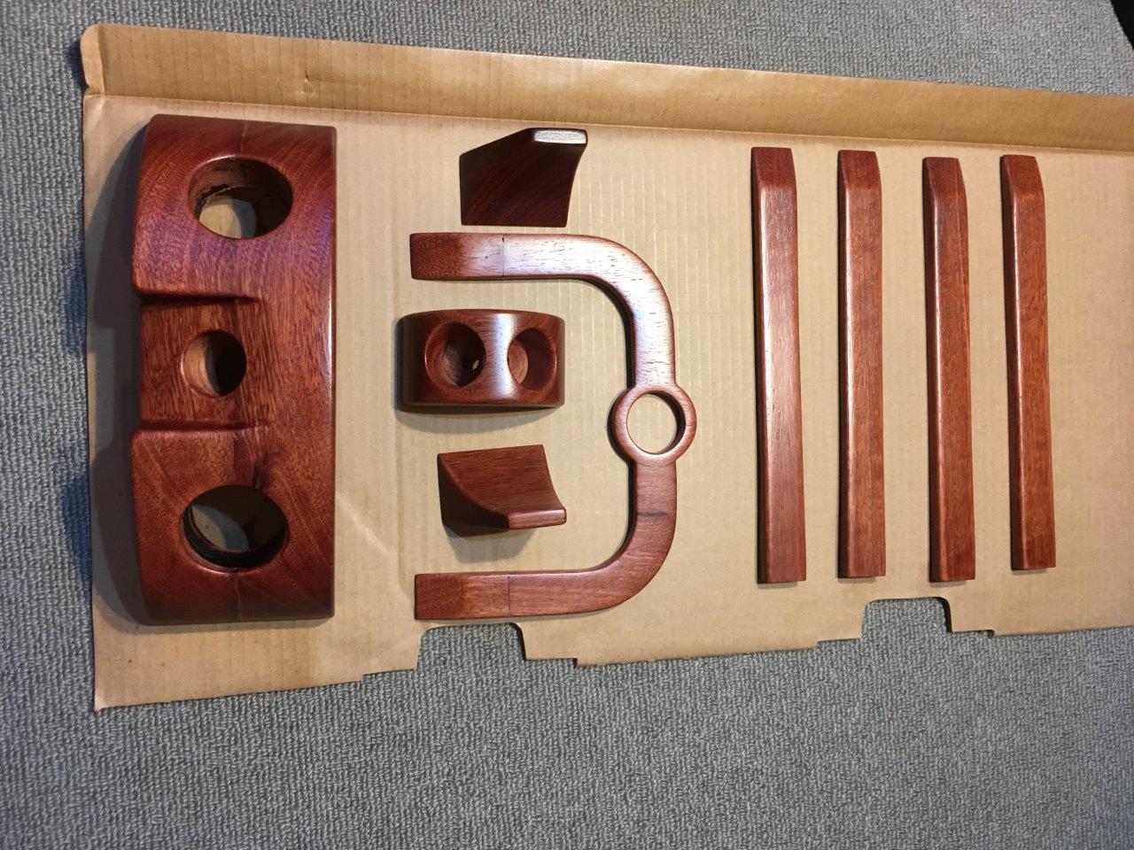
Finally, all the details are ready and sanded up to 400 grains:

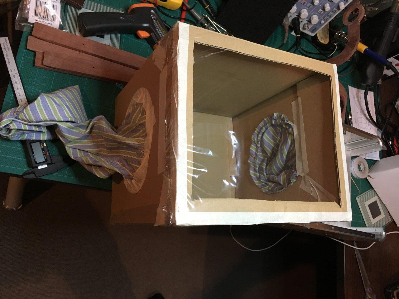
By the way, in the process of skinning, in order to protect the lungs and the carpet from wood dust, a unique tooling from a cardboard box and sleeves from an old shirt was used! A kind of home glovebox.
Then everything was covered with 4 layers of varnish:
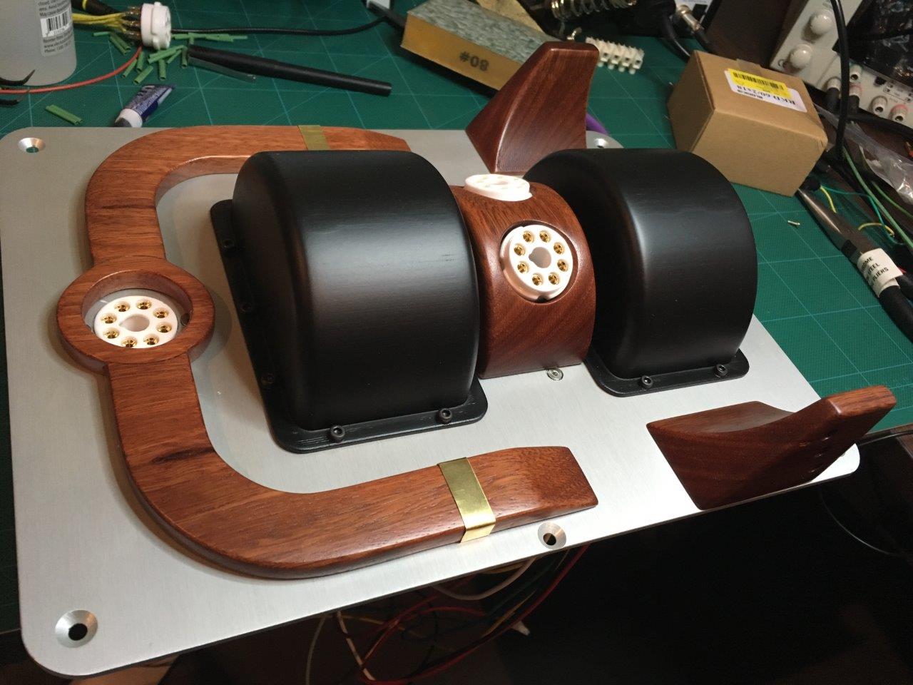
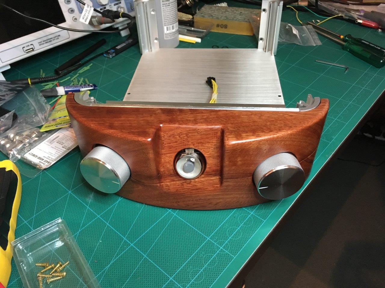
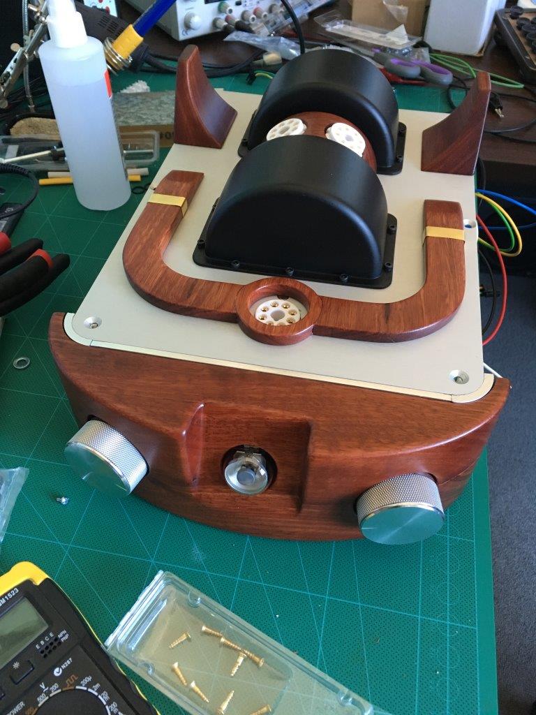
Well, then went to the gradual assembly:
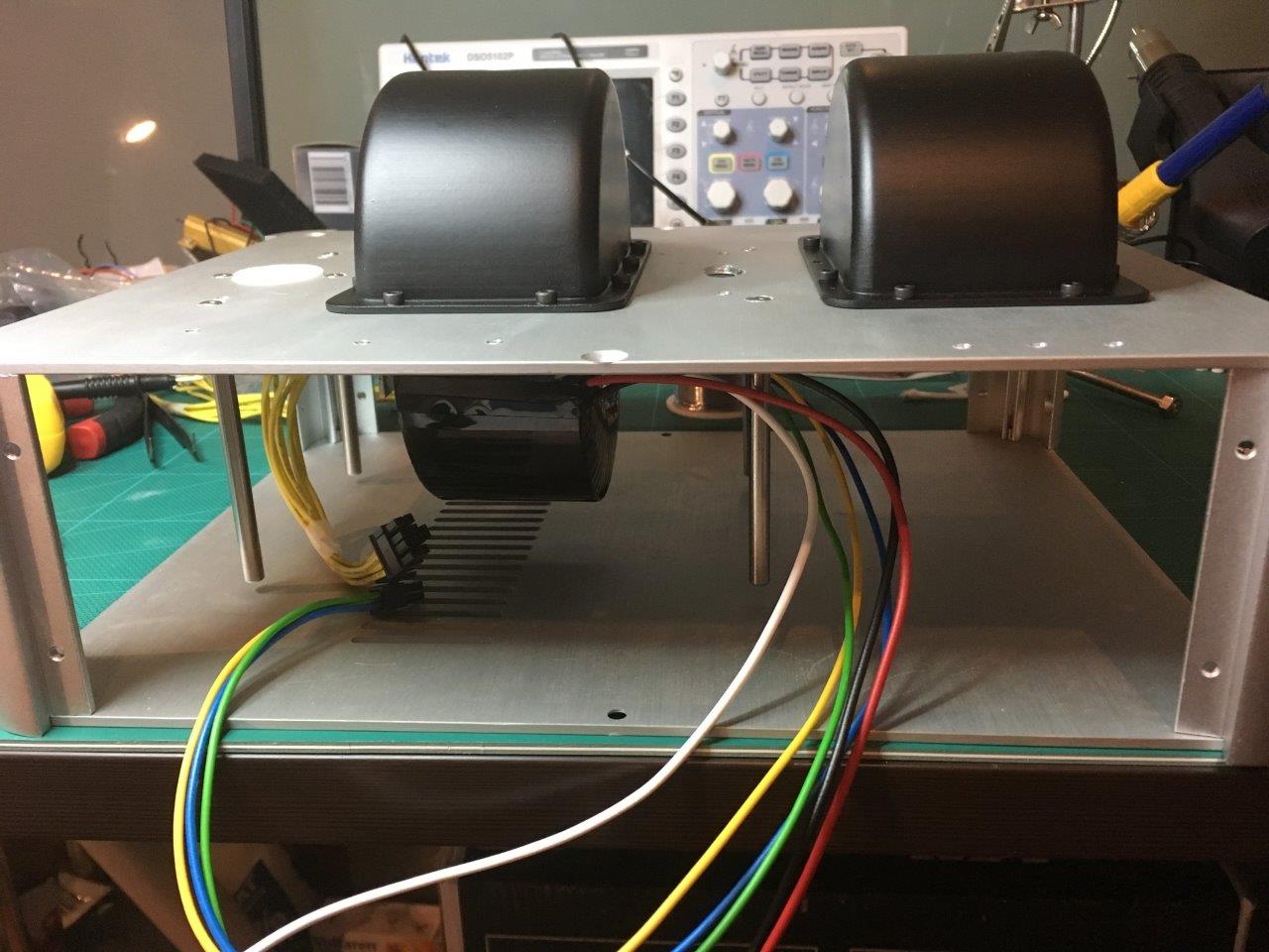
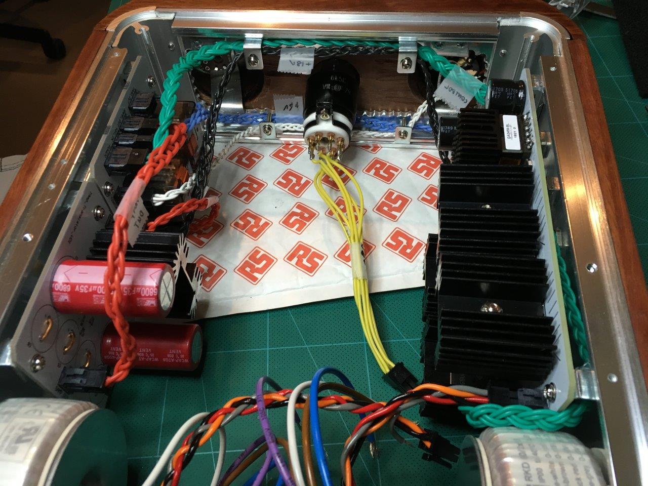
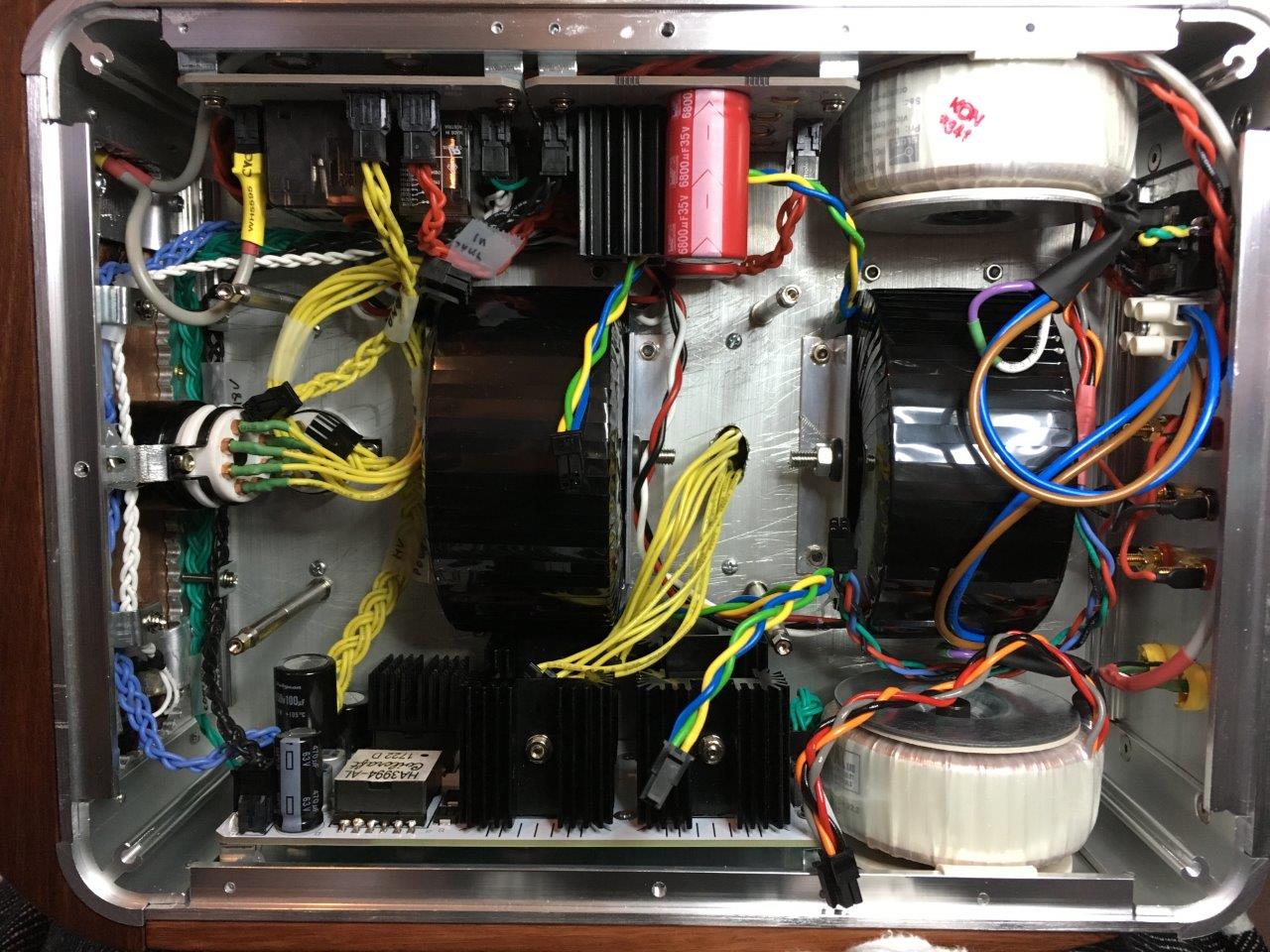
As I mentioned earlier, the boards and network transformers are attached to the side walls:

No jungle of wires, only braids, only beauty (the wires from the lamps were subsequently shortened):

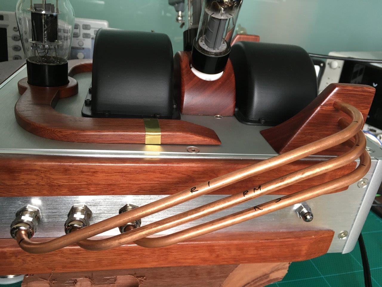
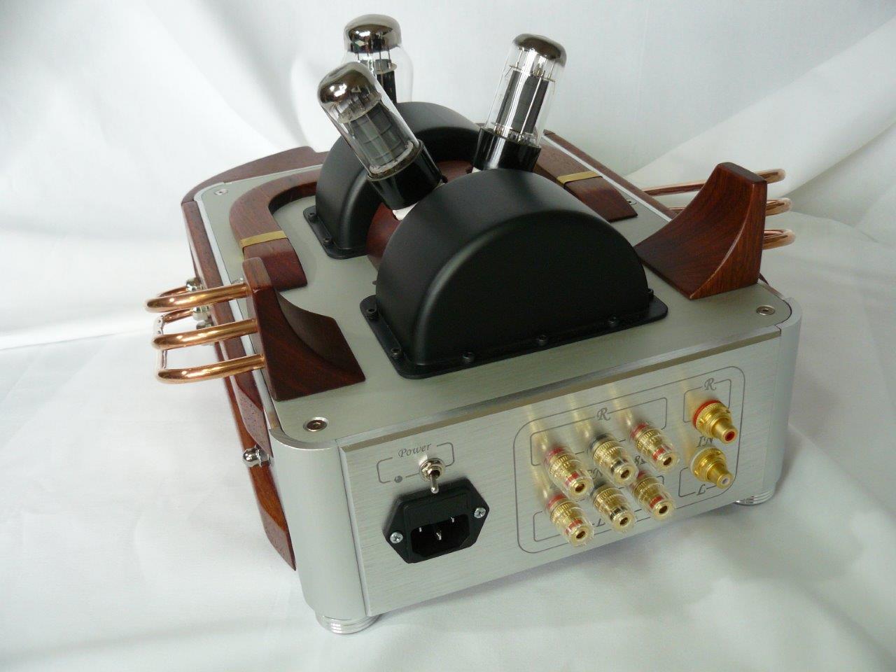
The markings on the rear panel were applied using laser engraving:

Device assembly without and with a tube amplifier board:

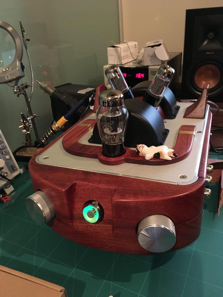
Final testing after assembly (the cat warms up near the lamp, all according to the canon):
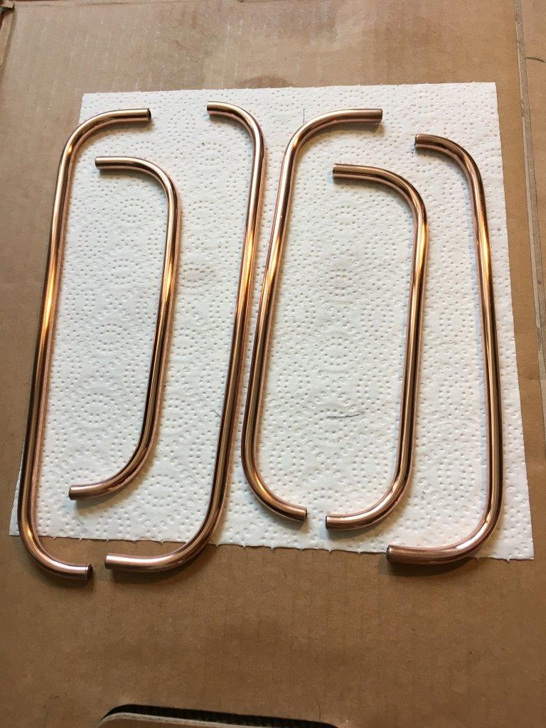
Polished copper pipes, without them:
Finally, all the details are ready and sanded up to 400 grains:
By the way, in the process of skinning, in order to protect the lungs and the carpet from wood dust, a unique tooling from a cardboard box and sleeves from an old shirt was used! A kind of home glovebox.
Then everything was covered with 4 layers of varnish:
Well, then went to the gradual assembly:
As I mentioned earlier, the boards and network transformers are attached to the side walls:
No jungle of wires, only braids, only beauty (the wires from the lamps were subsequently shortened):
The markings on the rear panel were applied using laser engraving:
Device assembly without and with a tube amplifier board:
Final testing after assembly (the cat warms up near the lamp, all according to the canon):
Polished copper pipes, without them:
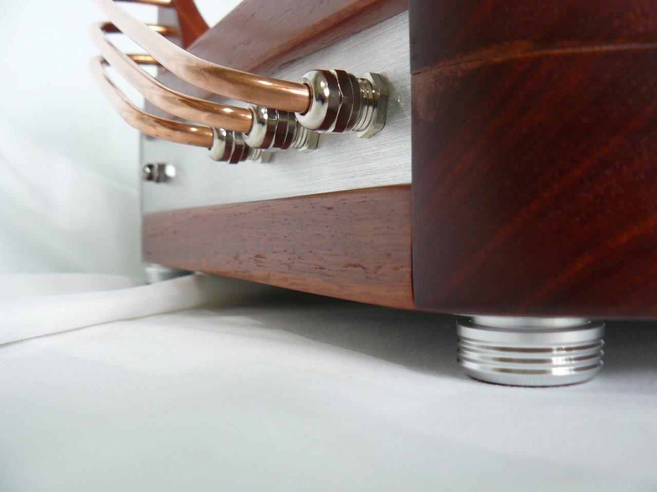
Below is the final photo session of the fully assembled device. There is also a clock on the gas-discharge indicators, which in fact squares the warmth and luminosity of the whole scene!
Final photo shoot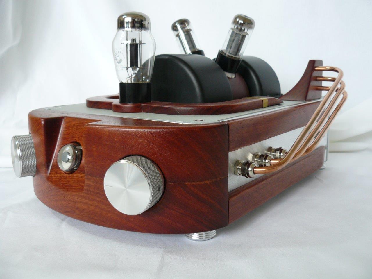
The end
On the whole project, from idea to implementation, it took about six months. Several analyzes and fees of the amplifier were left behind the frame in order to make changes and improvements, but this can be done endlessly. In general, the result pleased. As planned, in most cases a solid-state amplifier is used and only occasionally a tube is launched, mostly to compare. Nevertheless, the main goal - to revive his old hobby and dig deeper in electronics, was fully achieved! Write in the comments your questions and comments.
Have a great weekend everyone!
Source: https://habr.com/ru/post/434932/
All Articles