Part 2: Using Cypress UDB PSoC Controllers to Reduce the Number of Interrupts in a 3D Printer
Last time, we looked at the option of generating pulses for stepper motors, partly moved from the software to the microprogram level. In case of complete success, this promises no need to handle interrupts that come in at frequencies up to 40 KHz. But that option has some obvious flaws. First, accelerations are not supported there. Secondly, the granularity of the permissible frequencies of steps in that decision is hundreds of hertz (for example, generation of frequencies of 40,000 Hz and 3,996 Hz is possible, but generation of frequencies with a value between these two values is impossible).
Implementation of accelerations
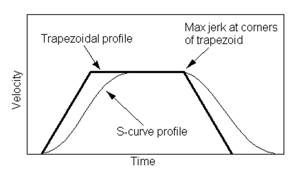
Is it possible to eliminate these shortcomings, using the tools of the same UDB, without complicating the system? Let's figure it out. Let's start with the most difficult - with accelerations. Accelerations are added at the beginning and end of the path. First, if a high frequency pulse is immediately applied to a stepping motor, it will need more current to start work. The high current allowed is heat and noise, so it’s best to limit it. But then the engine can skip steps at the start. So accelerate the engine better smoothly. Secondly, if a heavy head stops abruptly, then transient processes occur due to inertia. Waves are visible on the plastic. Therefore, it is necessary to smoothly not only accelerate, but also stop the head. Classically, the graph of engine speed is represented as a trapezoid. Here is a snippet from the Marlin “firmware” source code:

')
I will not even try to figure out whether it can be implemented using UDB. This is due to the fact that another type of acceleration is now coming into fashion: S-Curve, not trapezoidal. Their schedule looks like this:
This is definitely not for UDB. Give up Not at all! I have already noted that UDB does not implement a hardware interface for me, but simply allows you to transfer a part of the code from the software to the firmware level. Let the profile calculate the CPU, and the formation of step pulses still performs UDB. The central processor has a lot of time for calculations. The task of eliminating frequent interruptions will continue to be quite elegant, and no one has planned to completely remove the process to the firmware level.
Of course, the profile will need to be prepared in memory, and the UDB will take data from there using DMA. But how much memory is required? One millimeter needs 200 steps. Now with 24-bit encoding, this is 600 bytes per 1 mm of head movement! Again, remember about not so frequent, but still constant interruptions to transfer all the fragments? Not really! The fact is that the PSoC DMA mechanism is based on descriptors. After completing the task from one descriptor, the DMA controller proceeds to the next. And so, along the chain, you can use quite a lot of descriptors. We illustrate this with some drawing from the official documentation:
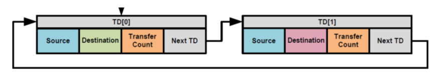
Actually, this mechanism can also be used by building a chain of three descriptors:
| No | Explanation |
|---|---|
| one | From memory in FIFO with address increment. Indicates a section with an acceleration profile. |
| 2 | From memory in FIFO without address increment. Sends all the time to the same word in memory for constant speed. |
| 3 | From memory in FIFO with address increment. Indicates a section with a braking profile. |
It turns out that the main path is described in step 2, and there is physically used the same word that defines a constant speed. Memory consumption is not great. In reality, the second descriptor can be physically represented by two or three descriptors. This is due to the fact that the maximum length of the transfer, according to the statements of TRM, may be 64 kilobytes (the amendment will be lower). That is, 32767 words. That at 200 steps per millimeter will correspond to a path of 163 millimeters. You may have to make a segment of two or three parts, depending on the maximum distance that the engine can go at a time.
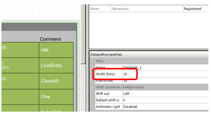
However, to save memory (and the consumption of UDB blocks), I propose to abandon the 24-bit DatapPath blocks by switching to more economical 16-bit ones.
So. The first sentence for revision.
Arrays encoding step lengths are prepared in memory. Further, this information goes to UDB using DMA. The straight-line segment is encoded by an array of one element, the DMA block does not increment the address, all the time choosing the same element. Acceleration, rectilinear movement and braking are connected by means available in the DMA controller.
Fine tuning of the average frequency
Now consider how to overcome the problem of frequency granularity. Of course, it will not be possible to set it. But, in fact, the original "firmware" also can not do this. Instead, they use the Brezenham algorithm. Some steps add a delay of one cycle. As a result, the average frequency becomes intermediate, between a smaller and larger value. By adjusting the ratio of standard and extended periods, you can smoothly change the average frequency. If the speed we now have is not set via the data register, but is transmitted via the FIFO, and the number of pulses is generally set via the number of words transmitted over the DMA, both data registers in the UDB are released. In addition, one of the batteries is released, which counted the number of pulses. Here we build a certain PWM on them.
Usually in the ALU registers are compared and assigned to the same index. When one register has an index of 0, and the other has 1, not any variant of the operation can be implemented. But I managed to add solitaire from the registers, at which PWM can be done. It turned out as shown in the figure.

When the condition A0 <D1 is fulfilled, we will add an extra beat to the given pulse length. When the condition is not met - we will not.
Spherical horse in normal conditions
So, we begin to modify the developed block for UDB, taking into account the new architecture. Replace Datapath bit:
We will need a lot more exits from Datapath than last time.
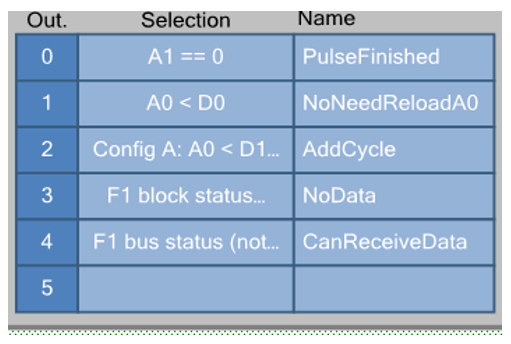
Double-clicking on them, see the details:

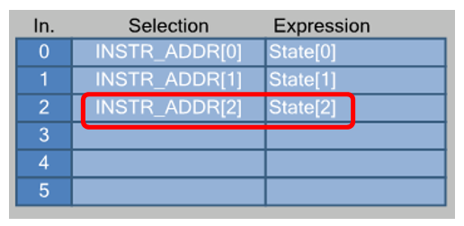
The State variable has more discharges, let's not forget to connect the senior !!! In the old version there was a constant 0.
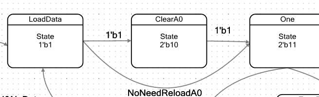
The transition graph of the machine I have turned out like this:

We are in the Idle state while FIFO1 is empty. By the way, working with FIFO1, and not FIFO0, is the result of the very addition of solitaire. Register A0 is used to implement PWM, so the pulse duration is determined by register A1. And I can download it only from FIFO1 (perhaps there are other secret methods, but I don’t know them). Therefore, DMA downloads the data to FIFO1, and it is exactly as “Not Empty” for FIFO1 that the Idle state will exit.
ALU in IDLE state zeros register A0:

This is necessary so that at the beginning of work, PWM always starts work from the beginning.
But here in the FIFO data fell. The machine enters the state LoadData :
In this state, the ALU loads the next word from the FIFO into the register A1. Along the way, in order not to create unnecessary states, the value of the A0 counter, which is used to work with PWM, increases:

If the counter A0 has not yet reached the value D0 (that is, the condition A0 <D0 triggers, setting the flag NoNeedReloadA0 ), we go to the One state. Otherwise, the state ClearA0 .
In the ClearA0 ALU state, the value of A0 simply vanishes , starting a new PWM cycle:

after which the machine also goes into the One state, just one clock later.
State One is familiar to us from the old version of the machine. ALU does not perform any functions in it.
And so - in this state, a unit is generated at the output of Out_Step (here the optimizer worked better when the unit is generated by the condition, it was revealed experimentally).
We are in this state until a seven-bit counter already known to us is reset. But if earlier we came out of this state along the same path, now there can be two paths: a straight line and a delay for a beat.
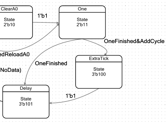
We’ll go to the ExtraTick state if the AddCycle flag is set , which is assigned to the condition A0 <D1. In this state, the ALU performs no useful actions. It's just that the loop is executed 1 clock longer. Then all the ways converge in a state of Delay .
This state measures the pulse duration. Register A1 (loaded while still in the Load state) decreases until it reaches zero.

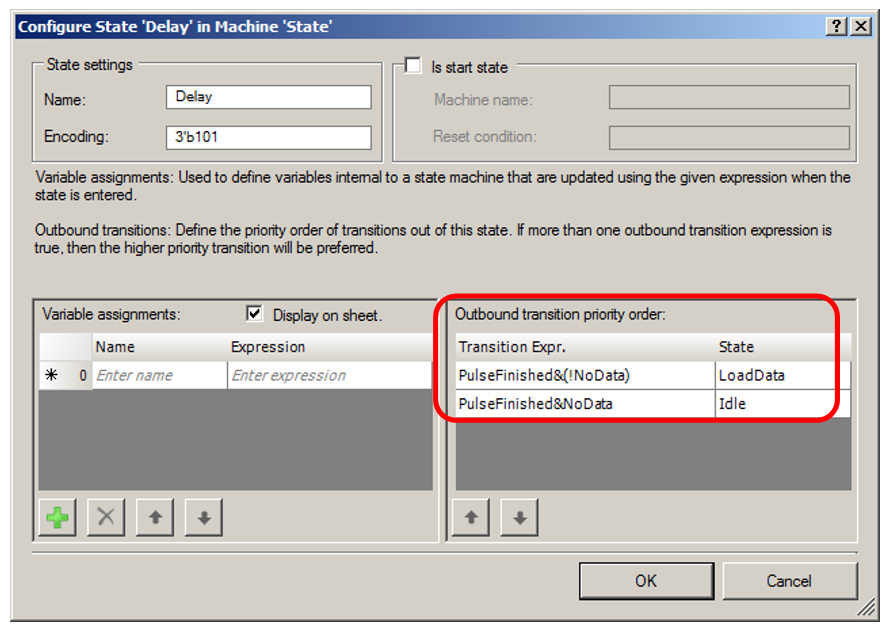
Further, depending on whether there are additional data in the FIFO or not, the machine will go to the next portion of the sample in the Load state or in the Idle state. Let's see it not in the figure (there are long arrows, everything will be fine), but in the form of a table, double clicking on the Delay state:
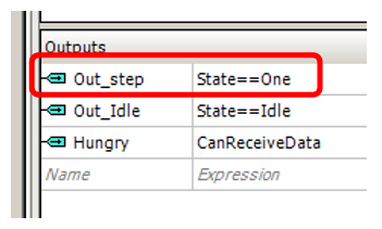
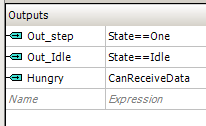
Now exits from UDB. I redid the flag in the Idle state for an asynchronous comparison (in the previous version there was a trigger that was cocked and reset in various states), since for it the optimizer showed the best result. Plus, the Hungry flag was added, signaling the DMA unit to be ready to receive data. He wound up on the flag "FIFO1 not crowded . " Once not full, the DMA can load the next data word there.
On the machine part - everything.
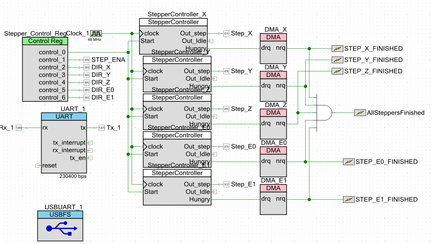
We add DMA blocks to the scheme of the main project. Interrupt, I still started on the end of DMA flags, but not the fact that this is correct. When the process of direct memory access is completed, you can start a new process that belongs to the same segment, but you cannot start filling in information about the new segment. In the FIFO is still from three to four elements. At this time, it is still impossible to reprogram the registers D0 and D1 of the block based on UDB, they are still needed for operation. Therefore, it is possible that interrupts will be added later on the basis of the Out_Idle outputs. But that kitchen will no longer be related to programming UDB blocks, so we will only mention it in passing.
Software experiments
Since everything is not known now, we will not write any special functions. All checks will be carried out "In the forehead." Then, based on successful experiments, the API functions can be written. So. The main () function is minimalistic. It simply configures the system and calls the selected test.
int main(void) { CyGlobalIntEnable; /* Enable global interrupts. */ // isr_1_StartEx(StepperFinished); StepperController_X_Start(); StepperController_Y_Start(); StepperController_Z_Start(); StepperController_E0_Start(); StepperController_E1_Start(); // TestShortSteps(); TestWithPacking (); for(;;) { } Let's try to send a burst of pulses by calling the function, checking the fact of inserting an additional pulse. The function call is simple:
TestShortSteps(); But the body needs clarification.
First I give the whole function.
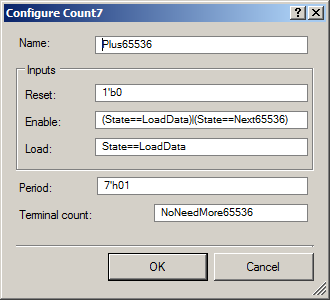
void TestShortSteps() { // , // // , DMA !!! // , !!! StepperController_X_SingleVibrator_WritePeriod (6); // // — CY_SET_REG16(StepperController_X_Datapath_1_D0_PTR, 4); CY_SET_REG16(StepperController_X_Datapath_1_D1_PTR, 2); // . // static const uint16 steps[] = { 0x0001,0x0001,0x0001,0x0001,0x0001,0x0001,0x0001,0x0001,0x0001,0x0001, 0x0001,0x0001,0x0001,0x0001,0x0001,0x0001,0x0001,0x0001,0x0001,0x0001 }; // DMA , uint8 channel = DMA_X_DmaInitialize (sizeof(steps[0]),1,HI16(steps),HI16(StepperController_X_Datapath_1_F1_PTR)); CyDmaChRoundRobin (channel,true); // , uint8 td = CyDmaTdAllocate(); // . , . CyDmaTdSetConfiguration(td, sizeof(steps), CY_DMA_DISABLE_TD, TD_INC_SRC_ADR | TD_AUTO_EXEC_NEXT); // CyDmaTdSetAddress(td, LO16((uint32)steps), LO16((uint32)StepperController_X_Datapath_1_F1_PTR)); // CyDmaChSetInitialTd(channel, td); // CyDmaChEnable(channel, 1); } Now consider the important parts of it.
If the length of the positive part of the pulse is equal to 92 cycles, then the oscilloscope will not see if there is a single-stroke inset in the negative part or not. The scale will not be the same. It is necessary to make the positive part as short as possible so that the total impulse would be comparable in scale with the inserted beat. Therefore, I forcibly change the period of the counter, which sets the duration of the positive part of the pulse:
// , // // , DMA !!! // , !!! StepperController_X_SingleVibrator_WritePeriod (6); But why as much as six cycles? Why not three? Why not two? Why, in the end, not one? It is a sad story. If the positive impulse is shorter than 6 clocks, then the system does not work. A long debugging on the oscilloscope with the output of test lines outward showed that DMA is not a quick thing. If an automaton works less than a certain duration, then by the time it exits the Delay state, the FIFO is most often empty. No new data word can be placed in it yet! And only when the positive part of the pulse has a duration of 6 cycles, the FIFO is guaranteed to have time to boot ...
Lyrical digression about latency
Another fix idea that sits in my head is hardware acceleration of certain functions of the core of our MAXROS. But alas, all my best ideas are broken about those same latencies.
It was the case, I studied the development of Bare Metal applications for Cyclone V SoC. But it turned out that working with single FPGA registers (when alternately writing into them, then reading from them) reduces the work of the core hundreds of (!!!) times. You heard right. It is in the hundreds. And all this is poorly documented, but I first smelled it, and then I proved from fragments of phrases from the documentation that the latency was at fault when requests passed through a bunch of bridges. If you need to drive a large array, there will also be latency, but in terms of one pumped word, it will not be significant. When requests are single (and hardware acceleration of the OS kernel implies them), the slowdown is exactly hundreds of times. It will be much faster to do everything in a purely program way when the program works with the main memory through the cache at a breakneck speed.
I also had some plans for PSoC. In appearance, you can wonderfully search for data in an array using DMA and UDB. What is really there! Due to the DMA descriptor structure of these controllers, it would be possible to conduct a complete hardware search in the linked lists! But having received the plug described above, I realized that it is also associated with latency. Here this latency is beautifully described in the documentation. Both in TRM on the family, and in a separate document AN84810 - PSoC 3 and PSoC 5LP Advanced DMA Topics . Section 3.2 is devoted to this. So the next hardware acceleration is canceled. A pity. But, as Semen Semenovich Gorbunkov said: "We will search."
We continue program experiments
Next, I set the parameters of the Brezenham algorithm:
// // — CY_SET_REG16(StepperController_X_Datapath_1_D0_PTR, 4); CY_SET_REG16(StepperController_X_Datapath_1_D1_PTR, 2); Well, the regular code goes further, transmitting an array of words via DMA to FIFO1 of the engine control unit X.
The result requires some explanation. Here he is:

Red shows the value of the counter A0, when the machine is in the state One . Green asterisk shows the cases when the delay is inserted due to finding the automaton in the ExtraTick state. There are still cycles where the delay is due to being in the ClearA0 state, they are marked with a blue grid.
As you can see, at the first entry, the very first delay is lost. This is due to the fact that A0 is cleared while in Idle , but increases when entering LoadData . Therefore, to the analysis point (exit from the One state) it is already equal to one. The score starts with her. But in general, it will not affect the average frequency. It just needs to be kept in mind. How to keep in mind that when A0 is reset, the beat will also be inserted. It must be taken into account when calculating the average frequency.
But in general, the number of pulses is correct. Their duration is also believable.
Let's try to program a more real chain of handles,
consisting of a plot of acceleration, linear motion and braking.
void TestWithPacking(int countOnLinearStage) { // , // . // , DMA !!! // , !!! StepperController_X_SingleVibrator_WritePeriod (6); // // — CY_SET_REG16(StepperController_X_Datapath_1_D0_PTR, 4); CY_SET_REG16(StepperController_X_Datapath_1_D1_PTR, 2); // static const uint16 accelerate[] = {0x0010,0x0008,0x0004}; // static const uint16 deccelerate[] = {0x004,0x0008,0x0010}; // . . static const uint16 steps[] = {0x0001}; // DMA , uint8 channel = DMA_X_DmaInitialize (sizeof(steps[0]),1,HI16(steps),HI16(StepperController_X_Datapath_1_F1_PTR)); CyDmaChRoundRobin (channel,true); // uint8 tdDeccelerate = CyDmaTdAllocate(); CyDmaTdSetConfiguration(tdDeccelerate, sizeof(deccelerate), CY_DMA_DISABLE_TD, TD_INC_SRC_ADR | TD_AUTO_EXEC_NEXT); CyDmaTdSetAddress(tdDeccelerate, LO16((uint32)deccelerate), LO16((uint32)StepperController_X_Datapath_1_F1_PTR)); // uint8 tdSteps = CyDmaTdAllocate(); // !!! // !!! CyDmaTdSetConfiguration(tdSteps, countOnLinearStage, tdDeccelerate, /*TD_INC_SRC_ADR |*/ TD_AUTO_EXEC_NEXT); CyDmaTdSetAddress(tdSteps, LO16((uint32)steps), LO16((uint32)StepperController_X_Datapath_1_F1_PTR)); // // !!! uint8 tdAccelerate = CyDmaTdAllocate(); CyDmaTdSetConfiguration(tdAccelerate, sizeof(accelerate), tdSteps, TD_INC_SRC_ADR | TD_AUTO_EXEC_NEXT); CyDmaTdSetAddress(tdAccelerate, LO16((uint32)accelerate), LO16((uint32)StepperController_X_Datapath_1_F1_PTR)); // CyDmaChSetInitialTd(channel, tdAccelerate); // CyDmaChEnable(channel, 1); } First, let's call for the same ten steps (in fact, 20 bytes go to DMA):
TestWithPacking (20); The result corresponds to the expectation. At the beginning is visible acceleration. And the exit to IDLE (blue ray) occurs with a large delay from the last pulse, it was then that the last step was completely completed, its value is approximately equal to the first one.
Real horse in normal conditions
When reworking the equipment, I somehow famously jumped from a 24-bit pulse width setting to a 16-bit one. But we found out that it is impossible to do this: the minimum frequency of the pulses will be too high. I did it intentionally. The fact is that the technique of expanding the 16-bit counter bit was so complicated that if I began to describe it with the main automaton, it would divert all attention to myself. Therefore, we consider it separately.
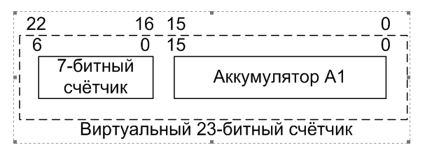
The battery is 16-bit. I decided to add to it the “seven-bit counter” entity in the older bits. What is this seven-bit counter? This is a design that exists in each UDB block (the UDB base block has a bit width of all 8-bit registers, the increase in bit depth is determined by the combination of the blocks into groups). From the same resources the Control / Status registers can be implemented. Now we have one counter for 16 data bits and not a single Control / Status pair. So, adding one more counter to the system, we will not pull off extra resources. We just take what is already allocated to us. Well, fine! We make the high byte of the pulse width counter through this mechanism and obtain the total bit width of the pulse width counter, equal to 23 bits.
First I will talk about what I was thinking. I thought that after leaving the Delay state, I would check the fact of the completion of the account of this additional counter. If he has not yet finished counting, I will decrease its value and again switch to the Delay state. If I counted, the logic will remain the same, without adding extra clock cycles.
Moreover, the documentation on this counter says that I am right. Literally it says:
PeriodLife has shown that everything is different. I brought the state of the terminal count line to the oscilloscope and observed its value with the preloaded zero in the Period and during software loading. Alas and ah. There was no constant high state !
Defines the initial period register value. For a period of N clocks, it should be set to the value of N-1. N-1 down to 0. The terminal count output is not supported at this constant high state.
Through trial and error, I managed to make the system work correctly, but for this, at least one subtraction from the counter should happen! The new state of "subtraction" is not the side. He had to wedge in the required path. It is located in front of the Delay state and is called Next65536 .
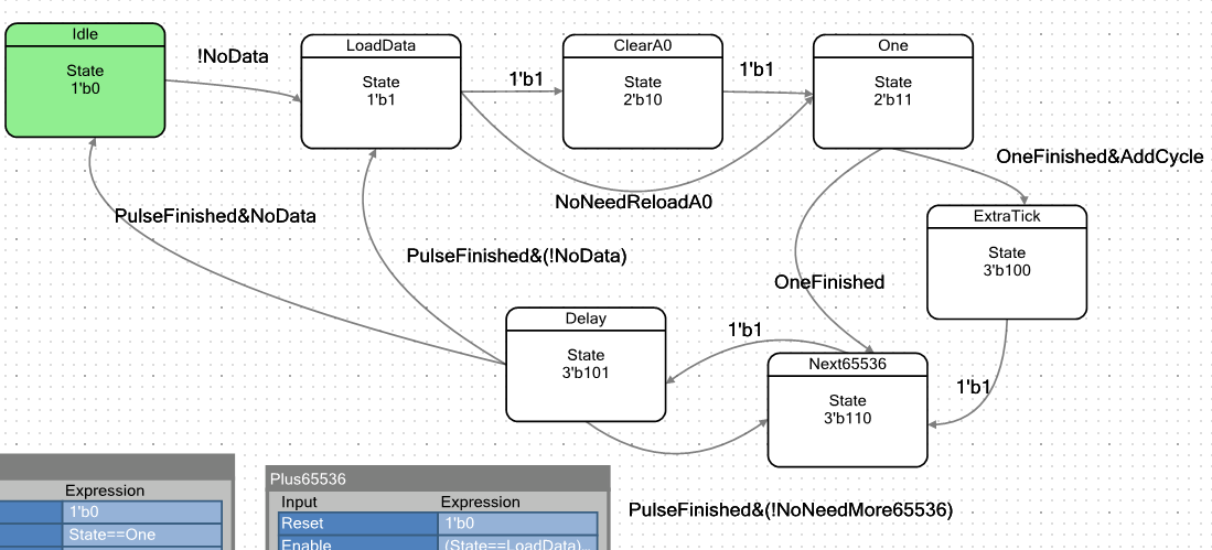
The ALU in this state does not perform any useful actions. Actually, only a new counter responds to the fact of being in this state. Here it is on the diagram:
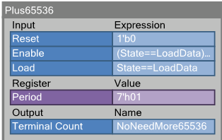
Here are its properties in more detail:
In general, taking into account the previous articles, the essence of this counter is clear. Only the string Enable has been gained. Again, I do not fully understand why it should be turned on when the machine is in the LoadData state (then the counter reloads the period value). I borrowed this trick from the properties of the meter that controls the LEDs, taken from the English author of the control unit for those LEDs. Without it, the zero period does not work. She works with her.
In the API code, we add initialization of the new counter. Now the start function looks like this:
void `$INSTANCE_NAME`_Start() { `$INSTANCE_NAME`_SingleVibrator_Start(); //"One" Generator start `$INSTANCE_NAME`_Plus65536_Start(); } Let's check the new system. Here is the function code for testing.
(only the first line differs from the already known one):
void JustTest(int extra65536s) { // 65536 StepperController_X_Plus65536_WritePeriod((uint8) extra65536s); // // — CY_SET_REG16(StepperController_X_Datapath_1_D0_PTR, 4); CY_SET_REG16(StepperController_X_Datapath_1_D1_PTR, 2); // . // static const uint16 steps[] = { 0x1000,0x1000,0x1000,0x1000 }; // DMA , uint8 channel = DMA_X_DmaInitialize (sizeof(steps[0]),1,HI16(steps),HI16(StepperController_X_Datapath_1_F1_PTR)); CyDmaChRoundRobin (channel,true); // , uint8 td = CyDmaTdAllocate(); // . , . CyDmaTdSetConfiguration(td, sizeof(steps), CY_DMA_DISABLE_TD, TD_INC_SRC_ADR | TD_AUTO_EXEC_NEXT); // CyDmaTdSetAddress(td, LO16((uint32)steps), LO16((uint32)StepperController_X_Datapath_1_F1_PTR)); // CyDmaChSetInitialTd(channel, td); // CyDmaChEnable(channel, 1); } Call it like this:
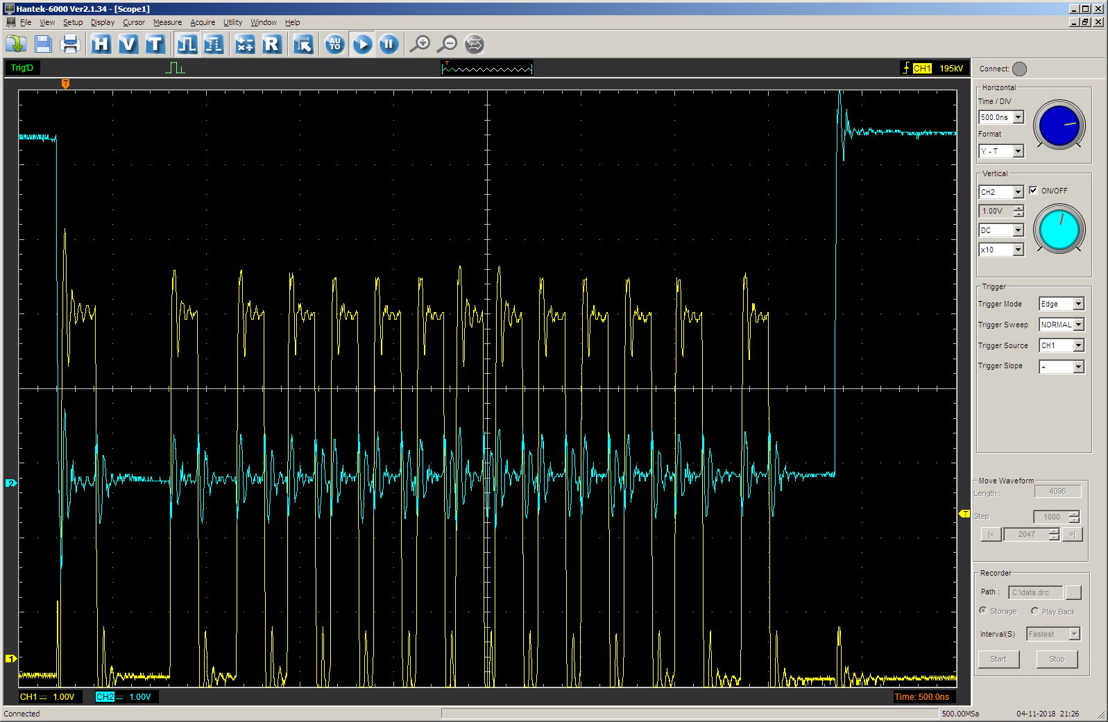
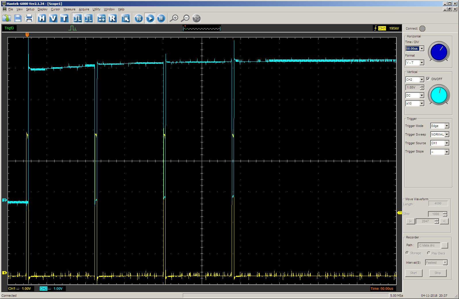
JustTest(0); On the oscilloscope we see the following (yellow beam - STEP output, blue - the value of the TC output of the counter for controlling the process). The pulse duration is specified in the steps array. At each step, the duration is 0x1000 cycles.
Switch to another development so that there is compatibility between different results:
Change the function call to this:
JustTest(1); The result corresponds to the expectation. First, the TC output is zero for 0x1000 cycles, then - one for 0x10000 (65536d) cycles. The frequency is approximately 700 Hertz, we found out in the last part of the article, so that's right.

Well, let's try a deuce:
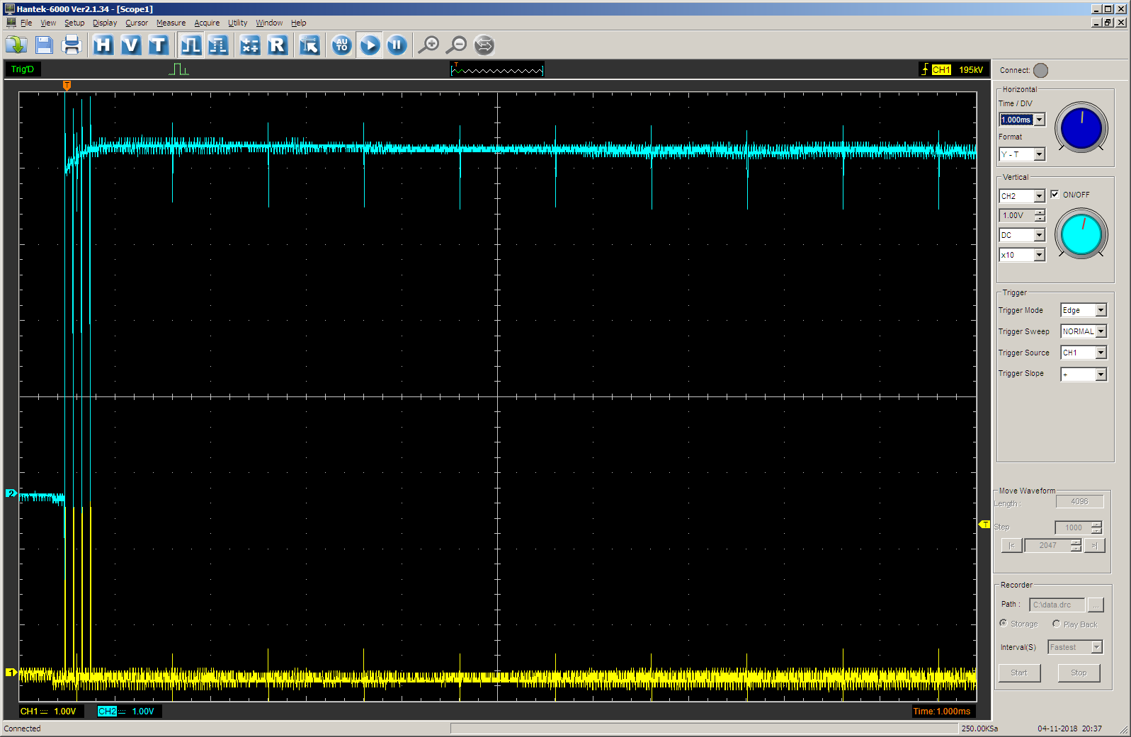
JustTest(2); We get:
That's right. The TC output is thrown to the unit at the last 65,536 cycles. Before that, it is at zero for 0x1000 + 0x10000 cycles.
Of course, with this approach, all the impulses must go at the same value of the new counter. It is impossible to make one pulse with a high byte, say, 3, then - 1, then - 0. But in fact, at such low frequencies (less than seven hundred hertz), the accelerations have no physical meaning, so this problem can be neglected. At this frequency, you can work with the engine linearly.
A spoon of tar
The TRM document for the PSoC5LP family reads:
Each transaction can be from 1 to 64 KBBut in the already mentioned AN84810 there is such a phrase:
1. How can you buffer more than 4095 bytes using DMA?Who is right? If experiments are conducted, the results will tend to favor the worst of the statements, but the behavior will be completely incomprehensible. All the fault of this check in the API:
The TDD is limited to 4095 bytes. If you need to use the DMA channel by 4095 bytes, it is shown in Example 5.
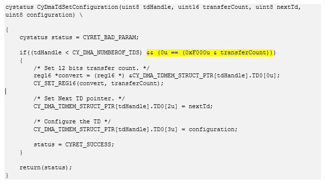
The same text.
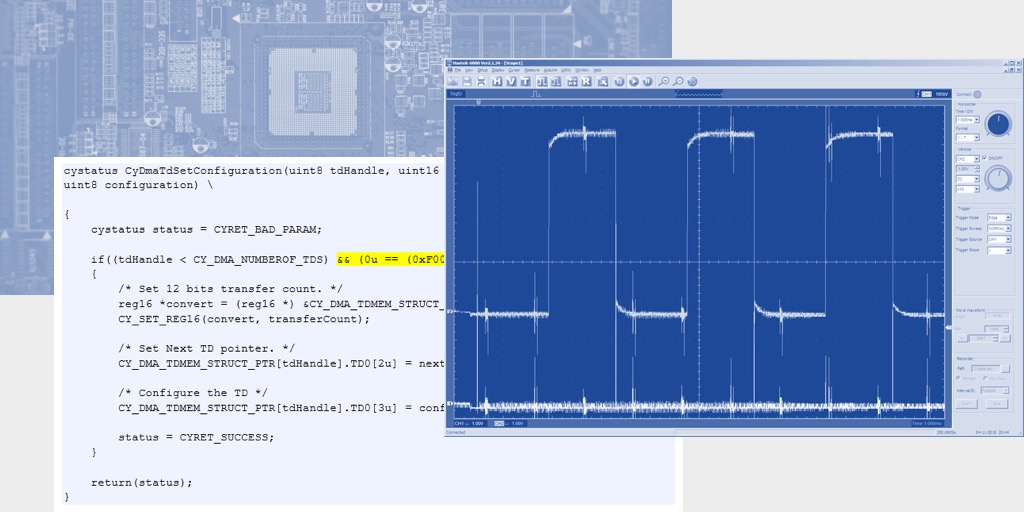
cystatus CyDmaTdSetConfiguration(uint8 tdHandle, uint16 transferCount, uint8 nextTd, uint8 configuration) \ { cystatus status = CYRET_BAD_PARAM; if((tdHandle < CY_DMA_NUMBEROF_TDS) && (0u == (0xF000u & transferCount))) { /* Set 12 bits transfer count. */ reg16 *convert = (reg16 *) &CY_DMA_TDMEM_STRUCT_PTR[tdHandle].TD0[0u]; CY_SET_REG16(convert, transferCount); /* Set Next TD pointer. */ CY_DMA_TDMEM_STRUCT_PTR[tdHandle].TD0[2u] = nextTd; /* Configure the TD */ CY_DMA_TDMEM_STRUCT_PTR[tdHandle].TD0[3u] = configuration; status = CYRET_SUCCESS; } return(status); } If a transaction is specified that is longer than 4095 bytes, the previous setting will be used. Yes, I did not think to check the error codes ...
Experiments have shown that if you remove this check, the actual length will be cut off using the 0xfff mask (4096D = 0x1000). Alas and ah. All hopes for a pleasant job collapsed. You can, of course, make chains of related 4K descriptors. But let's say, 64K is 16 chains. Three active engines (for extruders steps will be less) - 48 chains. Exactly so much must be filled in the worst case before each segment. Perhaps it is acceptable in time. At a minimum, 127 descriptors are available, so the memory will definitely suffice.
You can also send the missing data as needed. An interruption has come that the DMA channel has completed its work, we are transferring another segment to it. In this case, no calculations are required, the segment is already formed, everything will be fast. And there are no speed requirements: when an interrupt request is issued, there will be 4 more elements in the FIFO that will be serviced each for several hundred or even thousands of cycles. That is, everything is real. The specific strategy will be easier to choose during the actual work. But an error in the documentation (TRM) ruined the whole mood. If it were known in advance, maybe I would not even check the methodology.
Conclusion
In appearance, the developed auxiliary firmware tool became acceptable so that on its basis it was possible to make a version of the “Firmware”, say, Marlin, which is not permanently in the interrupt handler for stepper motors. As far as I know, this is especially true for Delta printers, where computing resources are quite high. Perhaps this will eliminate the influxes that occur on my Delta in places where the head stops. On MZ3D in the same places there are no flows. Like it or not, time will tell, and the report on this will need to be placed in a completely different branch.
In the meantime, we have seen that on the UDB block, for all its simplicity, it is quite possible to implement a coprocessor working in tandem with the main processor and allowing it to be unloaded. And when there are a lot of these blocks, coprocessors can work in parallel.
An error in the documentation for the DMA controller smeared the result. Interruptions are nevertheless required, but not at all at that frequency and with the time criticality that was in the original version. So the mood is spoiled, but the use of a "coprocessor" based on UDB still gives a considerable gain compared to purely software work.
Along the way, it was revealed that DMA is operating at a fairly low speed. Based on the results of this, some measurements were made on both the PSoC5LP and the STM32. The results pull on another article. Maybe I'll ever do it if the topic turns out to be interesting.
As a result of the experiments, two test projects turned out at once. The first is easier to understand. It can be taken here . The second is inherited from the first one, but it is confused when adding a seven-bit counter and its associated logic. It can be taken here . Of course, these examples are only test. There is no free time for embedding into real “firmware”. But within the framework of these articles, it is more important to practice working with UDB.
Source: https://habr.com/ru/post/434742/
All Articles