Minimalistic online simulator of linear DC and AC circuits
I'll tell you about my share that I used in my former job. Teaching theoretical electrical engineering involves solving many problems and performing experiments in the course of laboratory work. The results of solving a task or performing an experiment, naturally, it is advisable to check - what if an error occurred?
I decided to create a minimalistic simulator of linear electric circuits of constant and sinusoidal current FoxySim with text input of the description of the circuit, which requires using a device with a browser and the ability to enter text + Internet access.
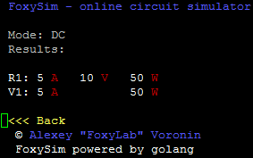
The browser can be any, even text - for example, the simulation in Lynx :
')
The circuit of the calculated circuit is described by a netlist consisting of directives, component descriptions and comments:
I made the format of the description in the spirit of SPICE with additions aimed precisely at the use in teaching theoretical electrical engineering (measuring instruments, complex values, etc.).
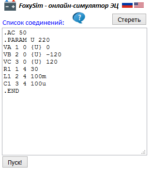
Enter the list of connections in the text field, for example, this one ( most of the lines have a fairly simple structure - for elements: name, initial node, final node, denomination; for ammeters and voltmeters: name, winding start node, winding end node, with wattmeter a little more complicated - he has two integral windings :-); You can also notice the value of the EMF, given as a parameter - so as not to repeat the same number three times )
Press the "Start!" button and get the result :-)

The entered description of the scheme is saved in cookies , you can switch the interface language.
The simulator is implemented on Go without any extras (I am delighted with this language) as a Web application.
For modeling electrical circuits, I used the MNA method.
The simulator is available at http://foxylab.com:7777
The project code is posted on GitHub .
Here are some examples:
DC circuit simulation
Scheme:
Connection list:
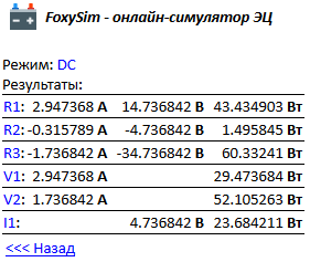
Result:
simulation of a linear sinusoidal current circuit
Scheme:
Connection list:
Result:

simulation of a complex asymmetric three-phase circuit with complex resistances
Scheme:
Connection list:
Result:
A brief description of the format of directives and descriptions of elements is available here (button )
)
A detailed description of the simulator can be found here .
A small video illustrating the process of modeling a sinusoidal current circuit -
Hidden text
The balance of electrical power is certainly a good thing, but you can make a mistake in it. Modeling comes to the rescue. Electric circuit simulators have a rich history, and to assemble a model of a DC circuit, for example, in LTspice will have no problems. But this is if the student has a laptop or an adequate computer park in the classroom. And this happens not always and not everywhere :-) There are simulators with a graphical interface and for smartphones, but the convenience of their use is a moot point. But even if the simulator is available, there is a peculiar problem with the simulation of the steady state of sinusoidal current circuits. If they are modeled in the " transient " mode, the question arises in view of the duration of the transition process that occurs when the circuit is turned on - the problem of " steady state detection ". But, you say, there is the " AC analysis " mode. This, of course, is true, but the convenience of using it and interpreting its results in solving the training problem of calculating a sinusoidal current circuit is a big fan. And the simulator also knows nothing about the reactive and full powers, and the definition of the wattmeter readings is far from trivial.
I decided to create a minimalistic simulator of linear electric circuits of constant and sinusoidal current FoxySim with text input of the description of the circuit, which requires using a device with a browser and the ability to enter text + Internet access.
The browser can be any, even text - for example, the simulation in Lynx :
')
The circuit of the calculated circuit is described by a netlist consisting of directives, component descriptions and comments:
I made the format of the description in the spirit of SPICE with additions aimed precisely at the use in teaching theoretical electrical engineering (measuring instruments, complex values, etc.).
Enter the list of connections in the text field, for example, this one ( most of the lines have a fairly simple structure - for elements: name, initial node, final node, denomination; for ammeters and voltmeters: name, winding start node, winding end node, with wattmeter a little more complicated - he has two integral windings :-); You can also notice the value of the EMF, given as a parameter - so as not to repeat the same number three times )
.AC 50 VA 1 0 {E} 0 VB 2 0 {E} -120 VC 3 0 {E} 120 .PARAM E 220 PW1 1 4 1 3 PW2 2 5 2 3 PAA 4 6 PAB 5 7 PAC 3 8 R1 6 9 500 L1 7 9 300m C1 8 9 50u PVA 6 9 PVB 7 9 PVC 8 9 PVN 9 0 .END Press the "Start!" button and get the result :-)
The entered description of the scheme is saved in cookies , you can switch the interface language.
The simulator is implemented on Go without any extras (I am delighted with this language) as a Web application.
For modeling electrical circuits, I used the MNA method.
The simulator is available at http://foxylab.com:7777
The project code is posted on GitHub .
Here are some examples:
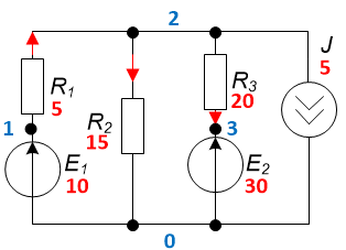
DC circuit simulation
Scheme:
Connection list:
.DC V1 1 0 10 R1 1 2 5 R2 2 0 15 R3 2 3 20 V2 3 0 30 I1 2 0 5 .END Result:
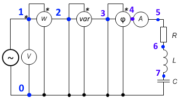
simulation of a linear sinusoidal current circuit
Scheme:
Connection list:
.AC 50 V1 1 0 100 0 PW1 1 2 1 0 PQ1 2 3 2 0 PF1 3 4 3 0 PA1 4 5 PV1 1 0 R1 5 6 50 L1 6 7 100m C1 7 0 80u .END Result:
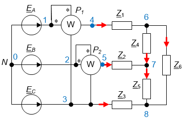
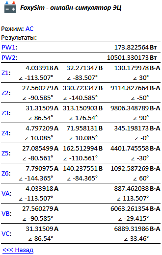
simulation of a complex asymmetric three-phase circuit with complex resistances
Scheme:
Connection list:
.AC 50 VA 1 0 {E} 0 VB 2 0 {E} -120 VC 3 0 {E} 120 .PARAM E 220 PW1 1 4 1 3 PW2 2 5 2 3 Z1 4 6 8 30 Z2 5 7 12 -50 Z3 3 8 10 90 Z4 6 7 15 0 Z5 7 8 6 -30 Z6 6 8 18 60 .END Result:
A brief description of the format of directives and descriptions of elements is available here (button
)A detailed description of the simulator can be found here .
A small video illustrating the process of modeling a sinusoidal current circuit -
Source: https://habr.com/ru/post/434570/
All Articles