GLSL: Center or centroid? Or when shaders attack
While modifying the shader for the upcoming game, I ran into an unpleasant artifact that manifests itself only when the MSAA hardware is turned on. In the screenshot of the landscape you can see several overly bright pixels. The color values in several of them were so great that after the bloom was applied they turned into multi-colored “ghosts”.

I offer you a translation of the article, which explains in detail the reason for this phenomenon and the way to combat it.

Figure 1 - Correct (left) and incorrect (right) images. Pay attention to the yellow bar at the left edge of the “incorrect” image. Although the variable myMixer varies from 0 to 1, it somehow falls outside this range in the “incorrect” image.
Consider a simple fragmentary shader with a simple non-linear transformation:
')
Where did the yellow bar on the left of the incorrect image come from? To better understand what went wrong, let's first consider the case in which everything works correctly (almost) always.
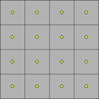
This is a classic rasterization with one sample. Gray squares are pixels, and yellow dots are pixel centers located in half-integer window coordinates (by default, the coordinates of the lower left pixel in gl_FragCoord are (0.5, 0.5) - transl. ).

In the picture above, the secant line separates the half-space of the primitive. Above and to the left of this line, the variable myMixer is positive, and below it and to the right is negative.
Classical single-sample rasterization classifies pixels according to their belonging to the primitive, and creates fragments only for pixels whose centers lie inside the primitive. In this example, six fragments will be produced, shown at the top left. Pixels marked with muted color do not fall into the primitive. Fragments will not be generated for them.

The green points mark the fragment shader to be calculated. The myMixer value will be calculated for the center of each pixel. Note that the green dots are above and to the left of the line, so the values of myMixer in them will be positive. All input data associated with vertices (varying or in / out variables) will also be interpolated at these points.
Our simple shader does not use derivatives (explicit or implicit, for example, when sampling from a texture with mip levels), but the arrows mark the derivatives dFdx (horizontal) and dFdy (vertical). Inside the primitive, they are quite well defined and regular.
To summarize: in a single sample, fragments are generated only if the center of the pixel falls inside the primitive, the fragment data is calculated for the center of the pixel, the interpolation of the vertex data and the shader calculation are performed only inside the primitive. Everything is good and "correct." (Almost always. For now, we omit the inaccuracies of some derivatives on pixels along the border of the primitive).
So, everything is (almost) excellent in rasterization with one sample. But what can go wrong when you turn on multisampling?
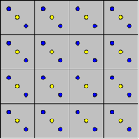
This is a classic rasterization with multisampling. Gray squares are pixels. Yellow dots - pixel centers in half-integer coordinates. Sampling occurs at blue points. This example shows a simple two-sample diagram with rotation. All reasoning can be generalized for an arbitrary number of samples.

The line still separates the half-space of the primitive. Above and to the left of it, the value of myMixer is positive. Below and to the right - negative.
When rasterizing with multisampling, the pixel classifier will generate a fragment if at least one pixel sample falls inside the primitive.
In this example, 10 fragments will be generated, shown in the upper left half-plane. Pay attention to the added four fragments along the face, in which one sample falls inside the primitive, although the center is outside. Pixels outside the primitive are still marked dim.

What will happen when calculating in the center of a pixel?
The shader will be calculated in green and red points for each of the fragments. The associated myMixer data is calculated at the center of each pixel. In the green points, these values will be positive, as they are higher and to the left of the border. Red points are outside the primitive, because the values of myMixer in them are negative. At red points, associated data is extrapolated instead of interpolating.
In our shader, the sqrt values (myMixer) are undefined with a negative myMixer. Even when the myMixer values, written by the vertex shader, lie in the segment from zero to one, in the fragment, the myMixer shader may go beyond this segment due to extrapolation. Thus, with a negative myMixer, the result of the fragment shader operation is not defined.
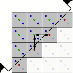
We still consider the calculation of the shader in the centers of pixels, the arrows in the figure show dFdx and dFdy. On the internal fragments of the polygon, they are quite well defined because all the calculations are done in the centers of pixels located at regular intervals.

What will happen when calculating at points other than pixel centers?
The green points are the points at which the shader will be calculated. The associated myMixer value is calculated at the centroid of each pixel.
A pixel centroid is the center of gravity of the intersection of the pixel square and the inside of the primitive. For a fully covered pixel, the centroid coincides with the center. For a partially covered pixel, the centroid is usually different from the center.
The OpenGL standard allows the implementation to choose an arbitrary point at the intersection of the primitive and the pixel instead of the ideal centroid. For example, it may be a sampling point.
In this example, if the center lies inside the primitive, the vertex data is calculated for the center. Otherwise, they are calculated at any of the sample points lying inside the primitive. This happens for four pixels along the border. All green dots lie above and to the left of the border, so the values in them are always interpolated and never extrapolated.
Why not calculate the shader in the centroid always? In general, it is more expensive than the calculation in the center. However, this is not a major factor.
It's all about calculating derivatives. Note the arrows between the green dots. The distance between them is not the same for different pairs of points. In addition, y is not a constant for dFdx, and x is not constant for dFdy. Derivatives are less accurate when calculated in centroids .
This is a compromise, and therefore OpenGL, starting with GLSL 1.20, offers the shader developer the choice between the center and the centroid with the help of the centroid qualifier:
When should centroid be used?
When should you not use a centroid?
I offer you a translation of the article, which explains in detail the reason for this phenomenon and the way to combat it.
Figure 1 - Correct (left) and incorrect (right) images. Pay attention to the yellow bar at the left edge of the “incorrect” image. Although the variable myMixer varies from 0 to 1, it somehow falls outside this range in the “incorrect” image.
Consider a simple fragmentary shader with a simple non-linear transformation:
')
smooth in float myMixer; // . // sqrt . void main( void ) { const vec3 blue = vec3( 0.0, 0.0, 1.0 ); const vec3 yellow = vec3( 1.0, 1.0, 0.0 ); float a = sqrt( myMixer ); // myMixer < 0.0 vec3 color = mix( blue, yellow, a ); // gl_FragColor = vec4( color, 1.0 ); } Where did the yellow bar on the left of the incorrect image come from? To better understand what went wrong, let's first consider the case in which everything works correctly (almost) always.
This is a classic rasterization with one sample. Gray squares are pixels, and yellow dots are pixel centers located in half-integer window coordinates (by default, the coordinates of the lower left pixel in gl_FragCoord are (0.5, 0.5) - transl. ).
In the picture above, the secant line separates the half-space of the primitive. Above and to the left of this line, the variable myMixer is positive, and below it and to the right is negative.
Classical single-sample rasterization classifies pixels according to their belonging to the primitive, and creates fragments only for pixels whose centers lie inside the primitive. In this example, six fragments will be produced, shown at the top left. Pixels marked with muted color do not fall into the primitive. Fragments will not be generated for them.
The green points mark the fragment shader to be calculated. The myMixer value will be calculated for the center of each pixel. Note that the green dots are above and to the left of the line, so the values of myMixer in them will be positive. All input data associated with vertices (varying or in / out variables) will also be interpolated at these points.
Our simple shader does not use derivatives (explicit or implicit, for example, when sampling from a texture with mip levels), but the arrows mark the derivatives dFdx (horizontal) and dFdy (vertical). Inside the primitive, they are quite well defined and regular.
To summarize: in a single sample, fragments are generated only if the center of the pixel falls inside the primitive, the fragment data is calculated for the center of the pixel, the interpolation of the vertex data and the shader calculation are performed only inside the primitive. Everything is good and "correct." (Almost always. For now, we omit the inaccuracies of some derivatives on pixels along the border of the primitive).
So, everything is (almost) excellent in rasterization with one sample. But what can go wrong when you turn on multisampling?
This is a classic rasterization with multisampling. Gray squares are pixels. Yellow dots - pixel centers in half-integer coordinates. Sampling occurs at blue points. This example shows a simple two-sample diagram with rotation. All reasoning can be generalized for an arbitrary number of samples.
The line still separates the half-space of the primitive. Above and to the left of it, the value of myMixer is positive. Below and to the right - negative.
When rasterizing with multisampling, the pixel classifier will generate a fragment if at least one pixel sample falls inside the primitive.
In this example, 10 fragments will be generated, shown in the upper left half-plane. Pay attention to the added four fragments along the face, in which one sample falls inside the primitive, although the center is outside. Pixels outside the primitive are still marked dim.
What will happen when calculating in the center of a pixel?
The shader will be calculated in green and red points for each of the fragments. The associated myMixer data is calculated at the center of each pixel. In the green points, these values will be positive, as they are higher and to the left of the border. Red points are outside the primitive, because the values of myMixer in them are negative. At red points, associated data is extrapolated instead of interpolating.
In our shader, the sqrt values (myMixer) are undefined with a negative myMixer. Even when the myMixer values, written by the vertex shader, lie in the segment from zero to one, in the fragment, the myMixer shader may go beyond this segment due to extrapolation. Thus, with a negative myMixer, the result of the fragment shader operation is not defined.
We still consider the calculation of the shader in the centers of pixels, the arrows in the figure show dFdx and dFdy. On the internal fragments of the polygon, they are quite well defined because all the calculations are done in the centers of pixels located at regular intervals.
What will happen when calculating at points other than pixel centers?
The green points are the points at which the shader will be calculated. The associated myMixer value is calculated at the centroid of each pixel.
A pixel centroid is the center of gravity of the intersection of the pixel square and the inside of the primitive. For a fully covered pixel, the centroid coincides with the center. For a partially covered pixel, the centroid is usually different from the center.
The OpenGL standard allows the implementation to choose an arbitrary point at the intersection of the primitive and the pixel instead of the ideal centroid. For example, it may be a sampling point.
In this example, if the center lies inside the primitive, the vertex data is calculated for the center. Otherwise, they are calculated at any of the sample points lying inside the primitive. This happens for four pixels along the border. All green dots lie above and to the left of the border, so the values in them are always interpolated and never extrapolated.
Why not calculate the shader in the centroid always? In general, it is more expensive than the calculation in the center. However, this is not a major factor.
It's all about calculating derivatives. Note the arrows between the green dots. The distance between them is not the same for different pairs of points. In addition, y is not a constant for dFdx, and x is not constant for dFdy. Derivatives are less accurate when calculated in centroids .
This is a compromise, and therefore OpenGL, starting with GLSL 1.20, offers the shader developer the choice between the center and the centroid with the help of the centroid qualifier:
centroid in float myMixer; // centroid smooth // . // sqrt . void main( void ) { const vec3 blue = vec3( 0.0, 0.0, 1.0 ); const vec3 yellow = vec3( 1.0, 1.0, 0.0 ); float a = sqrt( myMixer ); // myMixer < 0.0 vec3 color = mix( blue, yellow, a ); // gl_FragColor = vec4( color, 1.0 ); } When should centroid be used?
- When an extrapolated value can lead to undefined results. Pay special attention to the built-in functions, the description of which says "the result is not defined if ..."
- When the extrapolated value is used with a very non-linear or discontinuous function. These include the step function or the flare calculation, especially when the exponent is large enough.
When should you not use a centroid?
- If you need accurate derivatives. Derivatives can be either explicit (calling dFdx) or implicit, for example, samples from textures with mip levels or with anisotropic filtering. In the GLSL specification, the derivatives in the centroids are considered so unusable that they were declared undefined. In such cases, try to write:
centroid in float myMixer; // ! smooth in float myCenterMixer; // . - If a grid is rendered, in which most of the primitive boundaries are internal and always well defined. The simplest example is a strip of 100 triangles (TRIANGLE_STRIP), in which only the first and last triangles are extrapolated. The centroid qualifier will interpolate on these two triangles at the cost of loss of accuracy and continuity on the other 98 triangles.
- If you know that artifacts from an indefinite, nonlinear or discontinuous function may appear, but in practice these artifacts are almost invisible. If the shader does not attack - do not fix it!
Source: https://habr.com/ru/post/434046/
All Articles