Using QML Map to Build Airways - Part 1
I’ve been using QML for building graphical interfaces for quite a while, but the opportunity to work in a real project with the Qt Location API and QML Map hasn’t been until now.
Therefore, it became interesting to try this component to build airways.
Under the cut description of the implementation of the editor, to create such trajectories on the map:

To simplify the implementation, our planes fly in a 2D plane at the same height. Speed and permissible overload are fixed - 920 km / h and 3g, which gives a turning radius
The trajectory consists of segments of the following form:

where S is the beginning of the maneuver (it is the exit point from the previous one), M is the start of the turn, E is the exit from it, and F is the final point (M for the next).
For calculating the point of entry and exit from the trajectory, I used the equation of the tangent to the circle, the calculations were rather cumbersome, I am sure, it can be made easier.
')
Having completed the calculation of the mathematical model of our trajectory, let's get to work directly with the map. The natural choice for building broken lines on a QML map is to add a MapPolyline directly to the map.
Initially, I wanted to give the user the opportunity to model each next section of the route “on the fly” - to create an effect of movement of the trajectory behind the cursor.
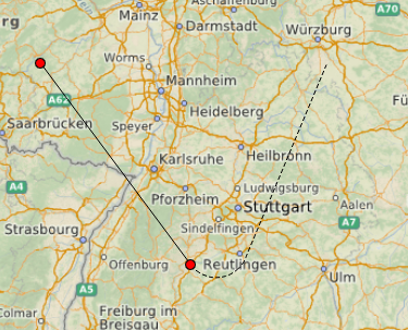
Changing the path when the cursor moves is quite a costly operation, so I tried to use preliminary “pixel” trajectories that are displayed until the user finally saves the route.
FlightItem is a QQuickItem , and QAbstractListModel flightModel allows you to update the necessary sections of the trajectory when changing data for maneuver.
Such a live update allows you to warn the user about unrealizable maneuvers.
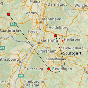
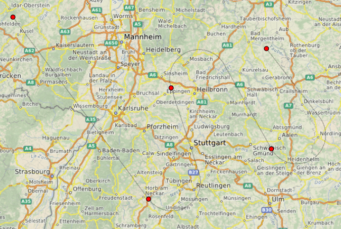
Only after the creation of the airway is completed (for example, when right mouse click), the route will finally be added to the QML Map as GeoPath with the possibility of geo-referencing (you cannot move and zoom the map until this moment, the pixels know nothing about longitude and latitude).
In order to convert the pixel segment into a geo-coordinate, we first need for each maneuver to use a coordinate system local relative to the point of entry into the maneuver (our point S).
After we recalculate the maneuver already meters, it is necessary to do the reverse operation and knowing the geo-referencing of the point S to convert meters to latitude-longitude.
From a formal point of view, of course, we cannot consider our “pixel” and “in meters” trajectory to be identical, but it seemed to me very tasty that I could look into the future and show the user what will happen (or not if the plane does not fly like this) when he will click next time. After finalizing the trajectory (it is slightly different from the pixel in color and transparency, since even static broken lines do not look very smooth on the map).
Sources are available here , used Qt 5.11.2 for compilation.
In the next part, we will teach our editor to move the reference points of the trajectory, as well as preserve / open existing tracks for subsequent imitation of the movement of aircraft.
Therefore, it became interesting to try this component to build airways.
Under the cut description of the implementation of the editor, to create such trajectories on the map:
To simplify the implementation, our planes fly in a 2D plane at the same height. Speed and permissible overload are fixed - 920 km / h and 3g, which gives a turning radius
The trajectory consists of segments of the following form:
where S is the beginning of the maneuver (it is the exit point from the previous one), M is the start of the turn, E is the exit from it, and F is the final point (M for the next).
For calculating the point of entry and exit from the trajectory, I used the equation of the tangent to the circle, the calculations were rather cumbersome, I am sure, it can be made easier.
')
void Manoeuvre::calculate() { // General equation of line between first and middle points auto A = mStart.y() - mMiddle.y(); auto B = mMiddle.x() - mStart.x(); // Check cross product sign whether final point lies on left side auto crossProduct = (B*(mFinal.y() - mStart.y()) + A*(mFinal.x() - mStart.x())); // All three points lie on the same line if (isEqualToZero(crossProduct)) { mIsValid = true; mCircle = mExit = mMiddle; return; } mIsLeftTurn = crossProduct > 0; auto lineNorm = A*A + B*B; auto exitSign = mIsLeftTurn ? 1 : -1; auto projection = exitSign*mRadius * qSqrt(lineNorm); // Center lies on perpendicular to middle point if (!isEqualToZero(A) && !isEqualToZero(B)) { auto C = -B*mStart.y() - A*mStart.x(); auto right = (projection - C)/A - (mMiddle.x()*lineNorm + A*C) / (B*B); mCircle.ry() = right / (A/B + B/A); mCircle.rx() = (projection - B*mCircle.y() - C) / A; } else { // Entering line is perpendicular to either x- or y-axis auto deltaY = isEqualToZero(A) ? 0 : exitSign*mRadius; auto deltaX = isEqualToZero(B) ? 0 : exitSign*mRadius; mCircle.ry() = mMiddle.y() + deltaY; mCircle.rx() = mMiddle.x() + deltaX; } // Check if final point is outside manouevre circle auto circleDiffX = mFinal.x() - mCircle.x(); auto circleDiffY = mFinal.y() - mCircle.y(); auto distance = qSqrt(circleDiffX*circleDiffX + circleDiffY*circleDiffY); mIsValid = distance > mRadius; // Does not make sence to calculate futher if (!mIsValid) return; // Length of hypotenuse from final point to exit point auto beta = qAtan2(mCircle.y() - mFinal.y(), mCircle.x() - mFinal.x()); auto alpha = qAsin(mRadius / distance); auto length = qSqrt(distance*distance - mRadius*mRadius); // Depends on position of final point find exit point mExit.rx() = mFinal.x() + length*qCos(beta + exitSign*alpha); mExit.ry() = mFinal.y() + length*qSin(beta + exitSign*alpha); // Finally calculate start/span angles auto startAngle = qAtan2(mCircle.y() - mMiddle.y(), mMiddle.x() - mCircle.x()); auto endAngle = qAtan2(mCircle.y() - mExit.y(), mExit.x() - mCircle.x()); mStartAngle = startAngle < 0 ? startAngle + 2*M_PI : startAngle; endAngle = endAngle < 0 ? endAngle + 2*M_PI : endAngle; auto smallSpan = qFabs(endAngle - mStartAngle); auto bigSpan = 2*M_PI - qFabs(mStartAngle - endAngle); bool isZeroCrossed = mStartAngle > endAngle; if (!mIsLeftTurn) { mSpanAngle = isZeroCrossed ? bigSpan : smallSpan; } else { mSpanAngle = isZeroCrossed ? smallSpan : bigSpan; } } Having completed the calculation of the mathematical model of our trajectory, let's get to work directly with the map. The natural choice for building broken lines on a QML map is to add a MapPolyline directly to the map.
Map { id: map plugin: Plugin { name: "osm" } MapPolyline { path: [ { latitude: -27, longitude: 153.0 }, ... ] } } Initially, I wanted to give the user the opportunity to model each next section of the route “on the fly” - to create an effect of movement of the trajectory behind the cursor.
Changing the path when the cursor moves is quite a costly operation, so I tried to use preliminary “pixel” trajectories that are displayed until the user finally saves the route.
Repeater { id: trajectoryView model: flightRegistry.hasActiveFlight ? flightRegistry.flightModel : [] FlightItem { anchors.fill: parent startPoint: start endPoint: end manoeuvreRect: rect manoeuvreStartAngle: startAngle manoeuvreSpanAngle: spanAngle isVirtualLink: isVirtual } } FlightItem is a QQuickItem , and QAbstractListModel flightModel allows you to update the necessary sections of the trajectory when changing data for maneuver.
QVariant FlightModel::data(const QModelIndex &index, int role) const { if (!index.isValid()) { return QVariant(); } switch (role) { case FlightRoles::StartPoint: return mFlight->flightSegment(index.row()).line().p1(); case FlightRoles::EndPoint: return mFlight->flightSegment(index.row()).line().p2(); ... } Such a live update allows you to warn the user about unrealizable maneuvers.
Only after the creation of the airway is completed (for example, when right mouse click), the route will finally be added to the QML Map as GeoPath with the possibility of geo-referencing (you cannot move and zoom the map until this moment, the pixels know nothing about longitude and latitude).
In order to convert the pixel segment into a geo-coordinate, we first need for each maneuver to use a coordinate system local relative to the point of entry into the maneuver (our point S).
QPointF FlightGeoRoute::toPlaneCoordinate(const QGeoCoordinate &origin, const QGeoCoordinate &point) { auto distance = origin.distanceTo(point); auto azimuth = origin.azimuthTo(point); auto x = qSin(qDegreesToRadians(azimuth)) * distance; auto y = qCos(qDegreesToRadians(azimuth)) * distance; return QPointF(x, y); } After we recalculate the maneuver already meters, it is necessary to do the reverse operation and knowing the geo-referencing of the point S to convert meters to latitude-longitude.
QGeoCoordinate FlightGeoRoute::toGeoCoordinate(const QGeoCoordinate &origin, const QPointF &point) { auto distance = qSqrt(point.x()*point.x() + point.y()*point.y()); auto radianAngle = qAtan2(point.x(), point.y()); auto azimuth = qRadiansToDegrees(radianAngle < 0 ? radianAngle + 2*M_PI : radianAngle); return origin.atDistanceAndAzimuth(distance, azimuth); } From a formal point of view, of course, we cannot consider our “pixel” and “in meters” trajectory to be identical, but it seemed to me very tasty that I could look into the future and show the user what will happen (or not if the plane does not fly like this) when he will click next time. After finalizing the trajectory (it is slightly different from the pixel in color and transparency, since even static broken lines do not look very smooth on the map).
Sources are available here , used Qt 5.11.2 for compilation.
In the next part, we will teach our editor to move the reference points of the trajectory, as well as preserve / open existing tracks for subsequent imitation of the movement of aircraft.
Source: https://habr.com/ru/post/433828/
All Articles