Font rendering with cover masks, part 1
When we started developing our performance profiler , we knew that we would perform almost the entire UI rendering on our own. Soon we had to decide which approach to use for font rendering. We had the following requirements:
- We need to be able to render any font of any size in real time in order to adapt to the system fonts and their sizes chosen by Windows users.
- Font rendering should be very fast, no braking is required when rendering fonts.
- In our UI, a lot of smooth animations, so the text should be able to smoothly move around the screen.
- It should be readable with small font sizes.
Not being at that time a great specialist in this matter, I searched the information on the Internet and found many techniques used to render fonts. I also talked to the technical director of Guerrilla Games Michiel van der Leu. This company experimented with a variety of font rendering methods and their rendering engine was one of the best in the world. Michil briefly outlined to me his idea of a new font rendering technique. Although the existing techniques would be quite enough for us, I was intrigued by this idea and I started to implement it, not paying attention to the wonderful world of font rendering that opened to me.
In this series of articles, I will describe in detail the technique we use, dividing the description into three parts:
- In the first part, we will learn how to render glyphs in real time using 16xAA sampled from a uniform grid.
- In the second part, we will move to a rotated grid, in order to beautifully perform anti-aliasing of horizontal and vertical edges. We will also see how the finished shader is almost completely reduced to one texture and lookup table.
- In the third part, we learn how to rasterize glyphs in real time using Compute and CPU.
You can see the finished results in the profiler, but here is an example of a screen with a Segoe UI font rendered using our font renderer:
')

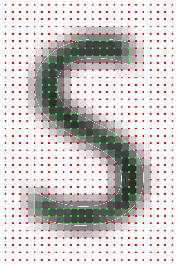
Here is an increase in the letter S, rasterized sizes of just 6 × 9 texels. The original vector data is rendered as a contour, and the rotated sampling pattern is rendered from green and red rectangles. Since it is rendered with a resolution much larger than 6 × 9, the shades of gray are not represented in the final pixel hue, it displays the subpixel hue. This is a very useful debug visualization, making it possible to make sure that all calculations at the subpixel level work correctly.
Idea: storing cover instead of shade
The main problem that font renderers need to deal with is the display of scalable font vector data in a fixed grid of pixels. The way to move from the vector space to the finished pixels in different techniques is very different. In most of these techniques, the curves before rendering are rasterized into temporary storage (for example, texture) to get a certain size in pixels. Temporary storage is used as the glyph cache: when the same glyph is rendered several times, the glyphs are taken from the cache and reused to avoid re-rasterization.
The difference technician is well marked in how data is stored in an intermediate data format. For example, the Windows font system rasterizes glyphs to a specific pixel size. Data is stored as a hue per pixel. The shade describes the best approximation of the coverage of this pixel glyph. When rendering, pixels are simply copied from the glyph cache to the target pixel grid. When converting data to a pixel format, they do not scale well, so when zooming out, fuzzy glyphs appear, and when zooming in, glyphs in which blocks are clearly visible. Therefore, for each finite size, the glyphs are rendered into the glyph cache.
The Signed Distanced Fields technique takes a different approach. Instead of a hue for a pixel, the distance to the nearest edge of the glyph is maintained. The advantage of this method is that for curved edges, the data is scaled much better than hues. As the glyph scale increases, the curves remain smooth. The disadvantage of this approach is that straight and sharp edges are smoothed out. Far better quality than SDF, are enhanced solutions like FreeType , which store hue data.
In cases where a hue is preserved for a pixel, it is necessary to first calculate its coverage. For example, in stb_truetype there are good examples of how to calculate the coverage and shade. Another popular way to approximate coverage is to sample the glyph with greater frequency than the final resolution. This counts the number of samples that fall into the glyph in the target pixel domain. The number of hits divided by the maximum number of possible samples determines shade. Since the coverage has already been converted to tint for a certain resolution of the pixel grid and alignment , it is impossible to place glyphs between the target pixels: the tint will not correctly reflect the true coverage with samples of the target pixel window. For this, as well as some other reasons that we will discuss later, such systems do not support sub-pixel movement.
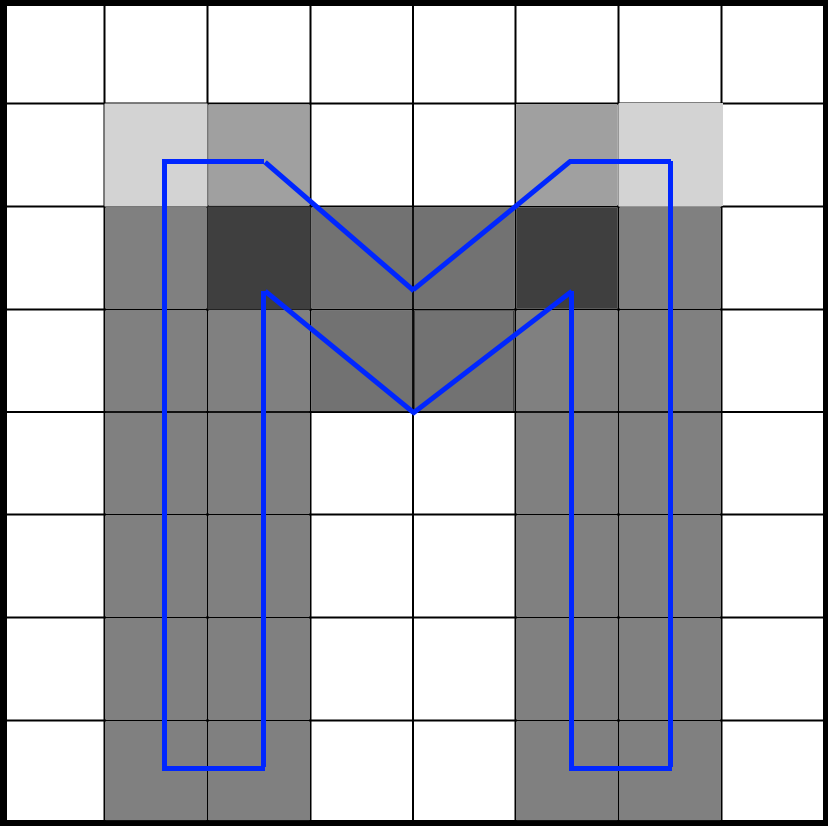
But what if we need to freely move the glyph between pixels? If the hue is calculated in advance, we cannot find out what the hue should be when moving between pixels in the target pixel region. However, we can postpone the conversion from coverage to tint at the time of rendering. To do this, we will not store the shade, but the coating . We sample a glyph with a frequency of 16 target resolution, and for each sample we save a single bit. When sampling on a 4 × 4 grid, it is enough to store only 16 bits per pixel. This will be our cover mask . During rendering, we need to consider how many bits fall into the target pixel window, which has the same resolution as the texel storage, but is not physically attached to it. The animation below shows a portion of the glyph (blue) rasterized into four texels. Each texel is divided into a grid of 4 × 4 cells. The gray rectangle indicates a pixel window dynamically moving along the glyph. At run time, the number of samples that fall into the pixel window is counted to determine the hue.
Briefly about the basic techniques of font rendering
Before discussing the implementation of our font rendering system, I want to briefly describe the main techniques used in this process: font hinting and subpixel rendering (in Windows this technique is called ClearType). You can skip this section if you are only interested in anti-aliasing technique.
During the implementation of the renderer, I learned more and more about the long history of font rendering development. Research is fully focused on the only aspect of font rendering - readability with small sizes. Creating an excellent renderer for large fonts is quite simple, but it is incredibly difficult to write a system that retains readability at small sizes. The study of font rendering has a long history, striking in its depth. Read, for example, about raster tragedy . It is logical that this was a major problem for computer specialists, because at the early stages of computers, the resolution of the screens was rather low. It must have become one of the first tasks that OS developers needed to cope with: how to make the text readable on devices with a low screen resolution? To my surprise, high-quality font rendering systems are very pixel-oriented. For example, the glyph is constructed in such a way that it starts at the border of a pixel, its width is a multiple of the number of pixels, and the content adjusts to the pixels. This technique is called grid binding. I am used to working with computer games and 3D graphics, where the world is built from units of measurement and projected into pixels, so I was a little surprised. I found out that in the field of font rendering it is a very important choice.
To show the importance of snapping to a grid, let's look at a possible scenario of rasterizing a glyph. Imagine that the glyph is rasterized on a pixel grid, but the shape of the glyph imperfectly coincides with the grid structure:
Antialiasing will make the pixels to the right and left of the glyph equally gray. If the glyph is slightly shifted so that it matches the edges of the pixels better, then only one pixel will be painted, and it will become completely black:
Now that the glyph matches the pixels well, the colors are not so blurry. The difference in sharpness is very large. Western fonts have a lot of glyphs with horizontal and vertical lines, and if they do not match well with the pixel grid, then shades of gray make the font blurry. Even the best antialiasing technique cannot cope with this problem.
Hinting of fonts was proposed as a solution. Font authors should add to their fonts information about how glyphs should snap to pixels if they do not match perfectly. The font rendering system distorts these curves to bind them to the pixel grid. This greatly increases the clarity of the font, but has its price:
- Fonts become slightly distorted . Fonts do not look exactly as intended.
- All glyphs must be tied to the pixel grid: the beginning of the glyph and the width of the glyph. Therefore, it is impossible to animate them between pixels.
Interestingly, in solving this problem, Apple and Microsoft went different ways. Microsoft adheres to absolute clarity, and Apple is committed to a more accurate display of fonts. On the Internet, you can find people's complaints about the blurring of fonts on Apple machines, but many people like what they see on Apple. That is partly a matter of taste. Here is the post of Joel on Software, and here is Peter Bilak 's post about this topic, but if you search on the Internet, you can find much more information.
Since the DPI resolution in modern screens is rapidly increasing, the question arises as to whether hinting fonts will be needed in the future, like today. In the current state, I consider font hinting to be a very valuable technique for accurate font rendering. However, the technique described in my article may in the future become an interesting alternative, because the glyphs can be freely placed on the canvas without distortion. And since this is essentially an antialiasing technique, it can be used for any purpose, and not just for font rendering.
Finally, I will tell you briefly about subpixel rendering . In the past, people have realized that you can triple the horizontal resolution of a screen using the individual red, green, and blue rays of a computer monitor. Each pixel is built from these rays, which are physically separated. Our eye blends their values, creating a single pixel color. When a glyph covers only part of a pixel, only the ray that overlaps the glyph is included, which triples the horizontal resolution. If you increase the screen image when using a technique like ClearType, you can see the colors around the edges of the glyph:

Interestingly, the approach, which I will discuss in the article, can be extended to sub-pixel rendering. I have already implemented its prototype. Its only drawback is that due to the addition of filtering in techniques like ClearType, we need to take more texture samples. Perhaps I will consider this in the future.
Glyph rendering using a uniform grid
Suppose we sampled a glyph with a resolution of 16 times the target and saved it into a texture. How this is done, I will tell in the third part of the article. The sampling pattern is a uniform grid, that is, 16 sampling points are evenly distributed over the texel. Each glyph is rendered with the same resolution as the target resolution, we store 16 bits per texel, and each bit corresponds to a sample. As we will see in the process of calculating the coverage mask, the order in which samples are stored is important. In general, the sampling points and their positions for a single texel look like this:

Getting texels
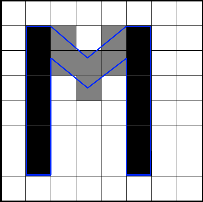
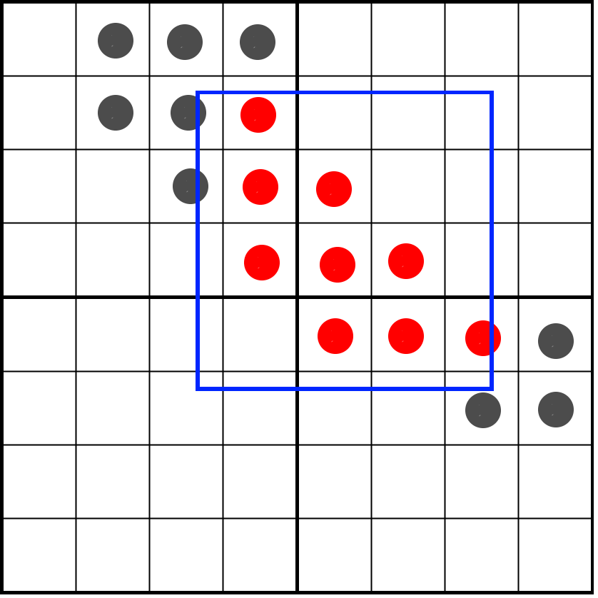
We will shift the pixel window over the bits of the coverage stored in texels. We need to answer the following question: how many samples will fall into our pixel window? It is illustrated by the following image:

Here we see four texels, on which the glyph is partially superimposed. One pixel (indicated in blue) covers part of the texels. We need to determine how many samples cross our pixel window. First we need the following:
- Calculate the relative position of the pixel window compared to 4 texels.
- Get the texels with which our pixel window intersects.
Our implementation is based on OpenGL, so the origin point of the texture space begins in the lower left corner. Let's start by calculating the relative position of a pixel window. The UV coordinate transmitted to the pixel shader is the UV coordinate of the pixel center. Assuming that UV is normalized, we can first convert UV into texel space by multiplying it by the size of the texture. Subtracting 0.5 from the center of the pixel, we get the lower left corner of the pixel window. By rounding this value down (floor), we calculate the bottom left position of the left bottom texel. The image shows an example of these three points in the texel space:
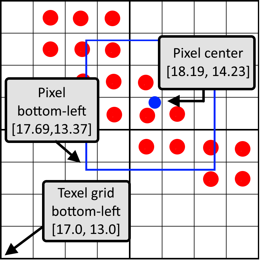
The difference between the lower left corner of the pixel and the lower left corner of the texel grid is the relative position of the pixel window in normalized coordinates. In this image, the position of the pixel window will be [0.69, 0.37]. In the code:
vec2 bottomLeftPixelPos = uv * size -0.5;
vec2 bottomLeftTexelPos = floor(bottomLeftPixelPos);
vec2 weigth = bottomLeftPixelPos - bottomLeftTexelPos;
Using the textureGather instruction, we can get four texels at a time. It is only available in OpenGL 4.0 and higher, so four texelFetch can be executed instead. If we just pass the textureGather UV coordinates, then if there is a perfect match between the pixel window and the texel, there will be a problem:
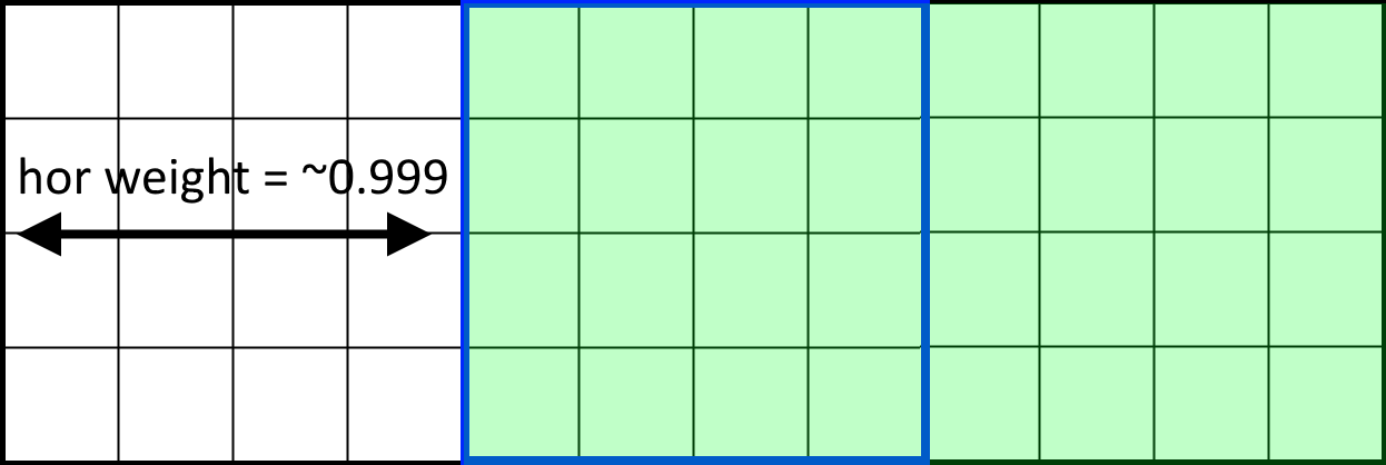
Here we see three horizontal texels with a pixel window (shown in blue) that exactly coincides with the central texel. The calculated weight is close to 1.0, but instead of textureGather, the center and right texels are selected. The reason is that calculations performed by textureGather may differ slightly from floating-point weight calculations. The difference in the rounding of the calculations performed in the GPU, and the calculations of the weight with a floating comma lead to glitches around the centers of the pixels.
To solve this problem, you need to make sure that the weight calculations are guaranteed to coincide with the textureGather sampling. To do this, we will never sample the pixel centers, and instead we will always perform sampling at the center of the 2 × 2 grid. From the computed and already rounded down left bottom position of the texel, we add the full texel to get to the center of the texel grid.
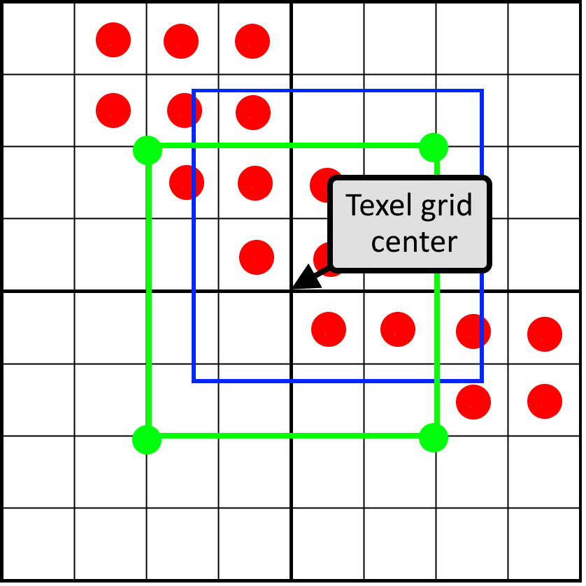
This image shows that using the center of the texel grid, the four sampling points taken by textureGather will always be in the center of texels. In the code:
vec2 centerTexelPos = (bottomLeftTexelPos + vec2(1.0, 1.0)) / size;
uvec4 result = textureGather(fontSampler, centerTexelPos, 0);
Horizontal pixel window mask
We got four texels and, together, they form a grid of 8 × 8 coverage bits. To count the bits in a pixel window, we first need to zero the bits that are outside the pixel window. To do this, we will create a pixel window mask and perform a bitwise AND between the pixel mask and texel cover masks. Horizontal and vertical masking are performed separately.
The horizontal pixel mask should move with the horizontal weight, as shown in this animation:
The image shows an 8-bit mask with the value 0x0F0 shifting to the right (zeros are inserted on the left). In animation, a mask is linearly animated with weight, but in reality, a bit shift is a step by step operation. The mask changes value when the pixel window crosses the border of the sample. In the next animation, this is shown in red and green columns, animated step by step. The value changes only at the intersection of the sample centers:

For the mask to move only in the center of the cell, but not at its edges, simple rounding will suffice:
unsigned int pixelMask = 0x0F0 >> int(round(weight.x * 4.0));Now we have a pixel mask of a full 8-bit string occupying two texels. If we choose the correct storage type in our 16-bit coverage mask, then there are ways to combine the left and right texel and perform horizontal pixel masking for the full 8-bit line at a time. However, this becomes problematic with vertical masking when we move to rotated grids. Therefore, instead of this, we will combine two left texels and two right texels separately to create two 32-bit coverage masks. We mask the left and right results separately.
Masks for left texels use the top 4 bits of the pixel mask, and masks for the right texels use the bottom 4 bits. In a uniform grid, each row has the same horizontal mask, so we can simply copy the mask for each row, after which the horizontal mask will be ready:
unsigned int leftRowMask = pixelMask >> 4;
unsigned int rightRowMask = pixelMask & 0xF;
unsigned int leftMask = (leftRowMask << 12) | (leftRowMask << 8) | (leftRowMask << 4) | leftRowMask;
unsigned int rightMask = (rightRowMask << 12) | (rightRowMask << 8) | (rightRowMask << 4) | rightRowMask;
To do the masking, we combine the two left texels and the two right texels, and then we mask the horizontal lines:
unsigned int left = ((topLeft & leftMask) << 16) | (bottomLeft & leftMask);
unsigned int right = ((topRight & rightMask) << 16) | (bottomRight & rightMask);
Now the result might look like this:

We can already calculate the bits of this result using the bitCount instruction. We should divide not by 16, but by 32, because after vertical masking we can still have 32 potential bits, not 16. Here is the full render of the glyph at this stage:

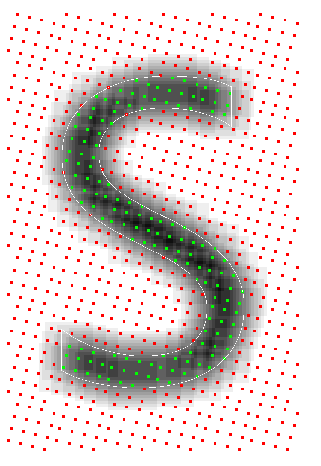
Here we see an enlarged letter S, rendered on the basis of the initial vector data (white contour), and the visualization of the sampling points. If the point is green, then it is inside the glyph; if it is red, then no. Grayscale displays the shades calculated at this stage. In the process of font rendering, there are many possibilities for errors, ranging from rasterization, the method of storing data in a texture atlas, to calculating the final hue. Such visualizations are incredibly useful for validating calculations. They are especially important for debugging artifacts at the sub-pixel level.
Vertical masking
Now we are ready to perform the masking of the vertical bits. For vertical masking, we use a slightly different method. In order to deal with the vertical shift, it is important to remember how we saved the bits: in a row order. The bottom line is the four least significant bits, and the top line is the four most significant bits. We can simply clear one by one, shifting them based on the vertical position of the pixel window.
We will create a single mask covering the entire height of the two texels. As a result, we want to save four full lines of texels and mask all the others, that is, the mask will be 4 × 4 bits, which is equal to the value 0xFFFF. Based on the position of the pixel window, we shift the bottom lines and clear the top lines.
int shiftDown = int(round(weightY * 4.0)) * 4;
left = (left >> shiftDown) & 0xFFFF;
right = (right >> shiftDown) & 0xFFFF;
As a result, we also masked vertical bits outside the pixel window:
Now it’s enough for us to count the bits remaining in texels, which can be done with the bitCount operation, then divide the result by 16 and get the desired shade!
float shade = (bitCount(left) + bitCount(right)) / 16.0;Now the full render of the letter looks like this:
In continuation of ...
In the second part, we will take the next step and see how this technique can be applied to rotated grids. We will calculate the following scheme:

And we will see that almost all of this can be reduced to several tables.
Thanks to Sebastian Aaltonen ( @SebAaltonen ) for his help in solving the textureGather problem and, of course, Michael van der Leu ( @MvdleeuwGG ) for his ideas and interesting conversations in the evenings.
Source: https://habr.com/ru/post/433670/
All Articles