Another simple processor on verilog
 The article describes another primitive processor and assembler for it.
Instead of the usual RISC / ISC, the processor does not have a set of instructions as such, there is only a single copy instruction.
Similar processors are at Maxim series MAXQ .
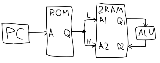
To begin, we describe the ROM, program memory
module rom1r(addr_r, data_r); parameter ADDR_WIDTH = 8; parameter DATA_WIDTH = 8; input [ADDR_WIDTH - 1 : 0] addr_r; output [DATA_WIDTH - 1 : 0] data_r; reg [DATA_WIDTH - 1 : 0] mem [0 : (1<<ADDR_WIDTH) - 1]; initial $readmemh("rom.txt", mem, 0, (1<<ADDR_WIDTH) - 1); assign data_r = mem[addr_r]; endmodule dual port RAM for data memory
module ram1r1w(clk_wr, addr_w, data_w, addr_r, data_r); parameter ADDR_WIDTH = 8; parameter DATA_WIDTH = 8; input clk_wr; input [ADDR_WIDTH - 1 : 0] addr_r, addr_w; output [DATA_WIDTH - 1 : 0] data_r; input [DATA_WIDTH - 1 : 0] data_w; reg [DATA_WIDTH - 1 : 0] mem [0 : (1<<ADDR_WIDTH) - 1]; assign data_r = mem[addr_r]; always @ (posedge clk_wr) mem[addr_w] <= data_w; endmodule and the processor itself
module cpu(clk, reset, port); parameter WIDTH = 8; parameter RAM_SIZE = WIDTH; parameter ROM_SIZE = WIDTH; input clk, reset; output [WIDTH-1 : 0] port; He, at a minimum, needs a command counter register, as well as one auxiliary register, and the IO port register, in order to have something to show outside our processor.
reg [WIDTH-1 : 0] reg_pc; reg [WIDTH-1 : 0] reg_reg; reg [WIDTH-1 : 0] reg_port; assign port = reg_port; The program counter will be the address for the program memory.
wire [WIDTH-1 : 0] addr_w, addr_r, data_r, data_w, data; rom1r rom (reg_pc, {addr_w, addr_r}); defparam rom.ADDR_WIDTH = ROM_SIZE; defparam rom.DATA_WIDTH = RAM_SIZE * 2; The double-width program memory contains two addresses: where and from where to copy data in a two-port data memory.
ram1r1w ram (clk, addr_w, data_w, addr_r, data_r); defparam ram.ADDR_WIDTH = RAM_SIZE; defparam ram.DATA_WIDTH = WIDTH; We denote special addresses: command counter, constant generator, check for 0 (for conditional jumps), addition / subtraction operations, and input / output port, in this case, for the time being, only output.
parameter PC = 0; parameter CG = 1; parameter TST = 2; parameter ADD = 3; parameter SUB = 4; parameter PORT = 5; The data buses of the two memory ports are not simply interconnected, but through multiplexers, which will at the same time fulfill the role of an ALU.
One multiplexer is on the data port of the reading port in order to read the command counter (for relative transitions), IO, etc., instead of the memory at certain addresses.
The second is on the write port data bus to not only transfer the data in memory, but also to change them when writing to certain addresses.
assign data = (addr_r == PC) ? reg_pc : (addr_r == PORT) ? reg_port : data_r; assign data_w = (addr_w == CG) ? addr_r : (addr_w == TST) ? |data : (addr_w == ADD) ? data + reg_reg : (addr_w == SUB) ? data - reg_reg : data; The auxiliary reg_reg register, which is used for arithmetic operations, is not directly accessible, but the result of each instruction is copied into it.
Thus, to add two values from the memory, one of them must first be read anywhere, for example, copy itself into itself (and at the same time in reg_reg), and the next recording command at the address of the adder will write there the sum with the previous value.
The constant generator writes the address itself, not the memory value at that address.
For unconditional jumps, simply copy the desired address to reg_pc, and for conditional jumps, reserve another TST address, which turns any non-zero value into 1, and at the same time increases the command counter by 2 instead of 1 to skip the command following it, if the result is not 0.
always @ (posedge clk) begin if (reset) begin reg_pc <= 0; end else begin reg_reg <= data_w; if (addr_w == PC) begin reg_pc <= data_w; end else begin reg_pc <= reg_pc + (((addr_w == TST) && data_w[0]) ? 2 : 1); case (addr_w) PORT: reg_port <= data_w; endcase end end end endmodule module rom1r(addr_r, data_r); parameter ADDR_WIDTH = 8; parameter DATA_WIDTH = 8; input [ADDR_WIDTH - 1 : 0] addr_r; output [DATA_WIDTH - 1 : 0] data_r; reg [DATA_WIDTH - 1 : 0] mem [0 : (1<<ADDR_WIDTH) - 1]; initial $readmemh("rom.txt", mem, 0, (1<<ADDR_WIDTH) - 1); assign data_r = mem[addr_r]; endmodule module ram1r1w(write, addr_w, data_w, addr_r, data_r); parameter ADDR_WIDTH = 8; parameter DATA_WIDTH = 8; input write; input [ADDR_WIDTH - 1 : 0] addr_r, addr_w; output [DATA_WIDTH - 1 : 0] data_r; input [DATA_WIDTH - 1 : 0] data_w; reg [DATA_WIDTH - 1 : 0] mem [0 : (1<<ADDR_WIDTH) - 1]; assign data_r = mem[addr_r]; always @ (posedge write) mem[addr_w] <= data_w; endmodule module cpu(clk, reset, port); parameter WIDTH = 8; parameter RAM_SIZE = 8; parameter ROM_SIZE = 8; parameter PC = 0; parameter CG = 1; parameter TST = 2; parameter ADD = 3; parameter SUB = 4; parameter PORT = 5; input clk, reset; output [WIDTH-1 : 0] port; wire [WIDTH-1 : 0] addr_r, addr_w, data_r, data_w, data; reg [WIDTH-1 : 0] reg_pc; reg [WIDTH-1 : 0] reg_reg; reg [WIDTH-1 : 0] reg_port; assign port = reg_port; rom1r rom(reg_pc, {addr_w, addr_r}); defparam rom.ADDR_WIDTH = ROM_SIZE; defparam rom.DATA_WIDTH = RAM_SIZE * 2; ram1r1w ram (clk, addr_w, data_w, addr_r, data_r); defparam ram.ADDR_WIDTH = RAM_SIZE; defparam ram.DATA_WIDTH = WIDTH; assign data = (addr_r == PC) ? reg_pc : (addr_r == PORT) ? reg_port : data_r; assign data_w = (addr_w == CG) ? addr_r : (addr_w == TST) ? |data : (addr_w == ADD) ? data + reg_reg : (addr_w == SUB) ? data - reg_reg : data; always @ (posedge clk) begin if (reset) begin reg_pc <= 0; end else begin reg_reg <= data_w; if (addr_w == PC) begin reg_pc <= data_w; end else begin reg_pc <= reg_pc + (((addr_w == TST) && data_w[0]) ? 2 : 1); case (addr_w) PORT: reg_port <= data_w; endcase end end end endmodule That's actually the whole processor.
Assembler
Now we will write for it a simple program that simply outputs the values to the port in sequence, and stops at 5.
Writing the assembler itself, even so simple (all the syntax is A = B), was lazy, so instead the basis was taken ready language Lua, which is very well suited for building various Domain Specific Language based on it, at the same time we get a ready Lua preprocessor .
First, the declaration of special addresses, the entry in which changes the data and variable of the counter at address 7
require ("asm") PC = mem(0) CG = mem(1) TST = mem(2) ADD = mem(3) SUB = mem(4) PORT = mem(5) cnt = mem(7) Instead of macros, you can use the usual Lua functions, though due to the fact that the _G metatable was changed to catch assignments (see below), global variables also fell off: declaring a non-local variable some_variable = 0xAA, our assembler will consider it “its” and try to parse it, instead, for declarations of the global preprocessor variable, you will have to use rawset (_G, some_variable, 0xAA), which does not touch the metamethods.
function jmp(l) CG = l PC = CG end Labels will be denoted by the word label and string constants; in Lua, in the case of a single string argument, the function of the bracket can be omitted.
label "start" Reset the port counter and register:
CG = 0 cnt = CG PORT = CG In the loop, load the constant 1, add it to the counter variable and show it to the port:
label "loop" CG = 1 ADD = cnt -- add = cnt + 1 cnt = ADD PORT = ADD We add the missing before overflow to 0 and, if there is not zero, go to the beginning, skipping CG = "exit", otherwise we end up in an infinite "exit" cycle.
CG = -5 ADD = ADD --add = add + 251 CG = "loop" TST = ADD --skip "exit" if not 0 CG = "exit" PC = CG label "exit" jmp "exit" require ("asm") PC = mem(0) CG = mem(1) TST = mem(2) ADD = mem(3) SUB = mem(4) PORT = mem(5) cnt = mem(7) function jmp(l) CG = l PC = CG end label "start" CG = 0 cnt = CG PORT = CG label "loop" CG = 1 ADD = cnt -- add = cnt + 1 cnt = ADD PORT = ADD CG = -5 ADD = ADD --add = add + 256 - 5 CG = "loop" TST = ADD --skip "exit" if not 0 CG = "exit" PC = CG label "exit" jmp "exit" And now the assembler asm.lua itself, as it should be in 20 lines:
In the mem function (for the declaration of special addresses), it would also be necessary to add an automatic assignment of the next free address, if it is not specified as an argument.
And for tags, you should check for redeclaration of an existing tag.
local output = {} local labels = {} function mem(addr) return addr end function label(name) labels[name] = #output end In Lua, there is no metamethod for assignment, but there are metamethods for indexing existing values and for adding new ones, including the _G global environment table.
Since __newindex works only for values that do not exist in the table, instead of adding new elements to _G, you have to hide them somewhere, without adding them to _G, and, accordingly, get them out when they are addressed through __index.
If the name already exists, then add this instruction to the others.
local g = {} setmetatable(_G, { __index = function(t, k, v) return g[k] end, __newindex = function(t, k, v) if g[k] then table.insert(output, {g[k], v}) else g[k]=v end end }) Well, after the execution of the assembler program, when the garbage collector finally comes for an array with our output program, we simply print it, at the same time replacing text labels with the correct addresses.
setmetatable(output, { __gc = function(o) for i,v in ipairs(o) do if type(v[2]) == "string" then v[2] = labels[v[2]] or print("error: ", v[2]) end print(string.format("%02X%02X", v[1] & 0xFF, v[2] & 0xFF)) end end }) local output = {} local labels = {} function mem(addr) return addr end function label(name) labels[name] = #output end local g = {} setmetatable(_G, { __index = function(t, k, v) return g[k] end, __newindex = function(t, k, v) if g[k] then table.insert(output, {g[k], v}) else g[k]=v end end }) setmetatable(output, { __gc = function(o) for i,v in ipairs(o) do if type(v[2]) == "string" then v[2] = labels[v[2]] or print("error: ", v[2]) end print(string.format("%02X%02X", v[1] & 0xFF, v[2] & 0xFF)) --FIX for WIDTH > 8 end end }) Running lua53 test.lua> rom.txt ( or online ) will get a program for the processor in machine codes.
0100 0701 0501 0101 0307 0703 0503 01FB 0303 0103 0203 010D 0001 010D 0001 For the simulation, we will make a simple testbench that only releases the reset and pulls the clocks.
`include "cpu.v" module test(); reg clk; reg reset; wire [7:0] port; cpu c(clk, reset, port); initial begin $dumpfile("test.vcd"); reset <= 1; clk <= 0; #4 reset <= 0; #150 $finish; end always #1 clk <= !clk; endmodule Using iverilog -o test.vvp test.v, open the resulting test.vcd in GTKWave: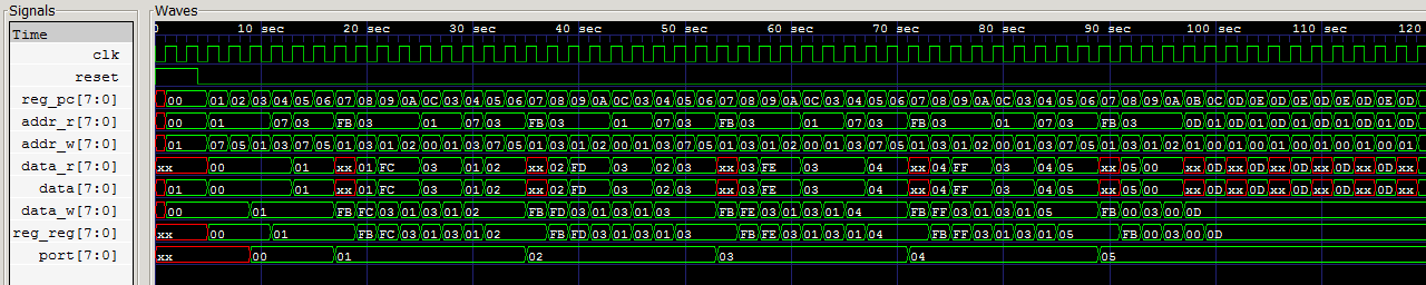
the port counts to five, and then the processor loops.
Now, when there is a minimal working processor, you can add the rest of arithmetic, logical operations, multiplication, division, floating point, trigonometry, registers for indirect memory access, stacks, hardware cycles, various peripherals, as needed, ... and start sawing backend for llvm.
')
Source: https://habr.com/ru/post/433342/
All Articles