Definition of numbers at the hearing: implementation on the Arduino
In this article I will continue to embody my inspiration with laboratory work No. 3 already in the gland. It will be about detecting the digit of the sound in the tone mode dialing on the Arduino using the algorithm of Goertzel.
To implement my plans, I used the Arduino UNO, an electret microphone ( adafruit ) and an 8x8 display with the MAX7219 driver.
Before embarking on an implementation, let's answer the question - will we have enough Arduino UNO performance?
Clock frequency: 16MHz
One sample cycle takes 13 cycles
The most accurate prescaler value: 128
')
It turns out 16 MHz / 13/128 ~ 9615 Hz - the desired sampling frequency, which means you can work with frequencies up to 4.8 kHz.
There are several modes of operation of the ADC, below are the most interesting (full list in the datasheet for the keyword ADCSRB)
ADC setup code, for simplicity, I used free-run mode.
As soon as the full array of samples is typed, turn off the ADC interrupt and calculate the amplitudes of the spectrum using the Goertzel algorithm. I will not compete in the description of the algorithm with this exhaustive resource , but I will give my implementation:
Sines and cosines were pre-calculated for the samples corresponding to the desired frequencies. The full version of the code is here .
The most important thing that turned out and resources Arduino UNO enough for easy sound processing.
The main lesson I learned was that the ADC is sensitive, after successfully recognizing and sending the symbol to the console, I spent a week debugging everything to work with the display, because I connected the microphone ground and max7219 and all the samples immediately turned into noise.
Could it have been made even better? Yes, it would be more correct to choose the sampling frequency and the number of samples so that the desired frequencies coincide with the sampling lattice, this would prevent the spreading of the spectrum. Such parameters are already f = 8 kHz, N = 205, in this case, you need to start the ADC not in the free-run mode, but the timer overflow, and the difference would be obvious.
The course comes to an end, but there are still a lot of ideas.
Thanks for attention.
To implement my plans, I used the Arduino UNO, an electret microphone ( adafruit ) and an 8x8 display with the MAX7219 driver.
Action plan
- To digitize a sufficient number of samples (using the program from the previous article, I made sure that 256 is enough).
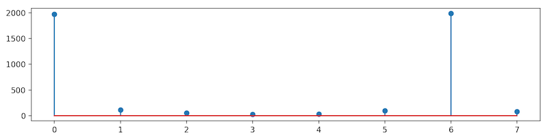
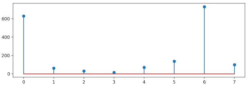
- Find the amplitude of the frequency response corresponding to the desired frequencies that encode the characters.
- The two maximum amplitude values will give the row and column indices of the character being searched for, for example, the number 3 looks like.
Implementation
Before embarking on an implementation, let's answer the question - will we have enough Arduino UNO performance?
Clock frequency: 16MHz
One sample cycle takes 13 cycles
The most accurate prescaler value: 128
')
It turns out 16 MHz / 13/128 ~ 9615 Hz - the desired sampling frequency, which means you can work with frequencies up to 4.8 kHz.
ADC setting
There are several modes of operation of the ADC, below are the most interesting (full list in the datasheet for the keyword ADCSRB)
- single read - using the analogRead () method, but this is a blocking call that takes 100µs, and using it cannot provide a constant sampling rate
- free-run mode - in this mode, the next sampling cycle begins immediately after the end of the previous one and provides the maximum sampling rate
- timer overflow - sampling starts when the timer overflows, this allows you to fine tune the sampling rate
ADC setup code, for simplicity, I used free-run mode.
ADMUX = 0; // Channel sel, right-adj, use AREF pin ADCSRA = _BV(ADEN) | // ADC enable _BV(ADSC) | // ADC start _BV(ADATE) | // Auto trigger _BV(ADIE) | // Interrupt enable _BV(ADPS2) | _BV(ADPS1) | _BV(ADPS0); // 128:1 / 13 = 9615 Hz ADCSRB = 0; // Free-run mode DIDR0 = _BV(0); // Turn off digital input for ADC pin TIMSK0 = 0; // Timer0 off Signal processing
As soon as the full array of samples is typed, turn off the ADC interrupt and calculate the amplitudes of the spectrum using the Goertzel algorithm. I will not compete in the description of the algorithm with this exhaustive resource , but I will give my implementation:
void goertzel(uint8_t *samples, float *spectrum) { float v_0, v_1, v_2; float re, im, amp; for (uint8_t k = 0; k < IX_LEN; k++) { float cos = pgm_read_float(&(cos_t[k])); float sin = pgm_read_float(&(sin_t[k])); float a = 2. * cos; v_0 = v_1 = v_2 = 0; for (uint16_t i = 0; i < N; i++) { v_0 = v_1; v_1 = v_2; v_2 = (float)(samples[i]) + a * v_1 - v_0; } re = cos * v_2 - v_1; im = sin * v_2; amp = sqrt(re * re + im * im); spectrum[k] = amp; } } Sines and cosines were pre-calculated for the samples corresponding to the desired frequencies. The full version of the code is here .
findings
The most important thing that turned out and resources Arduino UNO enough for easy sound processing.
The main lesson I learned was that the ADC is sensitive, after successfully recognizing and sending the symbol to the console, I spent a week debugging everything to work with the display, because I connected the microphone ground and max7219 and all the samples immediately turned into noise.
Could it have been made even better? Yes, it would be more correct to choose the sampling frequency and the number of samples so that the desired frequencies coincide with the sampling lattice, this would prevent the spreading of the spectrum. Such parameters are already f = 8 kHz, N = 205, in this case, you need to start the ADC not in the free-run mode, but the timer overflow, and the difference would be obvious.
The course comes to an end, but there are still a lot of ideas.
Thanks for attention.
Source: https://habr.com/ru/post/432498/
All Articles