STM32 bootloader DFU mode using CubeMX. Instructions step by step, step by step
So, the essay of this mandala was driven by the almost complete absence of step-by-step instructions using the usual tools offered by STMicroelectronics.
The great number of bootloaders found in the network, sometimes quite entertaining, are unfortunately “sharpened” for any particular crystal.
The proposed material contains the procedure for using the CubeMX package, the DfuSeDemo “downloads” and the Dfu file manager firmware preparation utilities, i.e., we abstract our hot hardware from the hardware, forgive me the macro assembler and datasheet.
Cooking environment ...
')
We need the actual CubeMX itself, the download of the DfuSeDemo + Dfu file manager, are in one package, the STM32 ST-LINK Utility, we are looking for everything on the STMicroelectronics website for free.
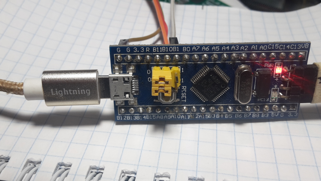
Our guinea pig with a STM32F103C8T6 chip from Uncle Liao
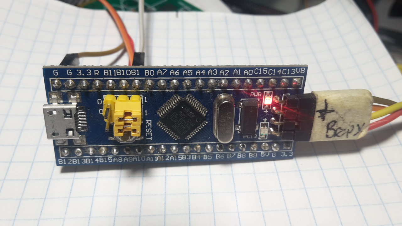
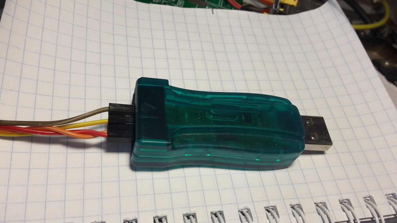
and the ST-Link programmer from there.
Well, your favorite IDE, in this particular presentation, we use KEIL, the compilation settings in other IDEs are not very different.
So let's go ...
Launch CubeMX and choose your crystal ...

We mark our Wishlist ...
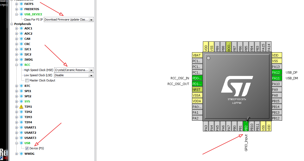
In this particular task, we activate the USB device → Device FS and, accordingly, the USB Device → DownLoad Update Firmware class, and the RCC → High Speed Clock → Cristal / Ceramic Resonator is unforgettable on board.
Next, you need to select the bootloader mode switch, in this example, simply use the available jumper boot1.

We look at the scheme and, in accordance with it, boot1 is attached to the leg of PB2, so we will use it in the GPIO_Input mode.
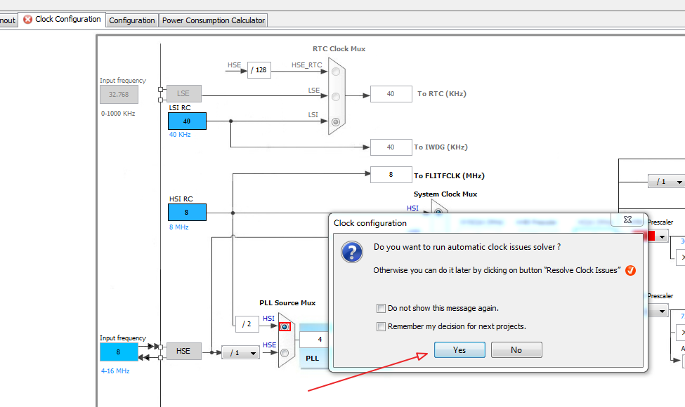
Done, activate the Clock Configuration tab and start the configuration selection machine.
Jump to the Cofiguration tab ...
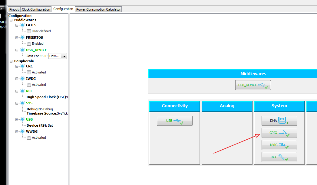
Choosing the GPIO button ...

And in the field ...
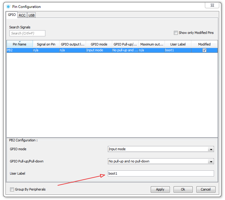
write a custom label, let it be boot1.
Next, set up the project ...

Choose Project → Setting ...
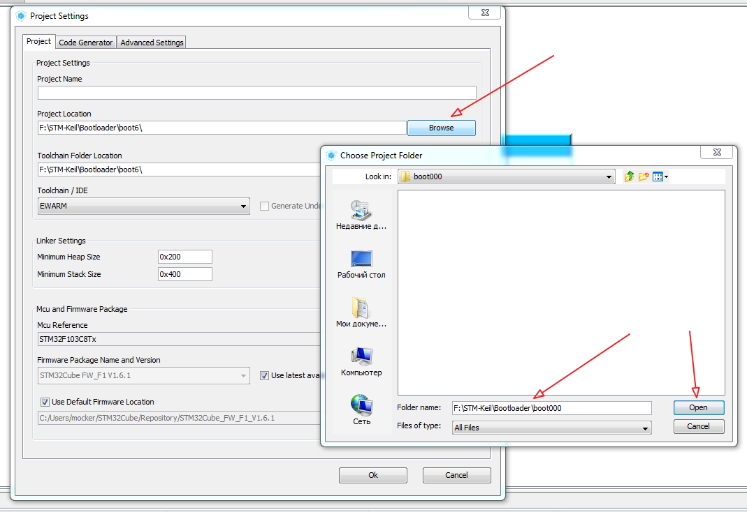
Choose and fill ...
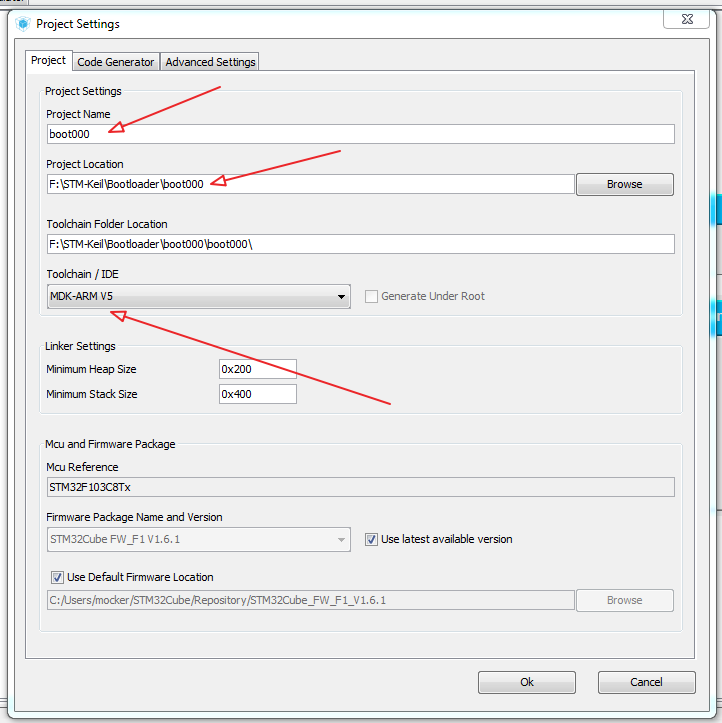
Accordingly, we choose for which IDE a Cub to us will generate a project, in our case, MDK-ARM V5.
Bookmark the Code Generator in this embodiment will remain unchanged ...
Well, that's all, run the generation of the project Project → Generate Code
When finished, Cub will offer to immediately launch your IDE ... how to proceed to choose you.

We start compilation and assembly and loading into a crystal ... F7, F8 ...
The end result ...
Switch the pins on our board to the operation mode and connect the USB cable ...
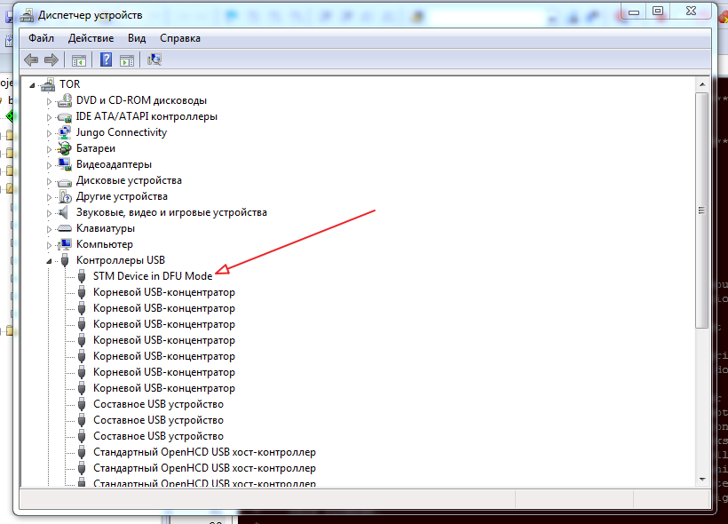
Open the control panel in Windows → system → device manager → USB controller. And we look at the list of devices, Windows silently rustles and installs the STM Device driver in DFU Mode (if it was not already installed).
So, the driver got up and decided, run the DfuSeDemo “bootloader” ...
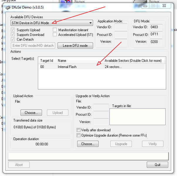
We look at what a DFU Device has caught and click on the Select Target field ...
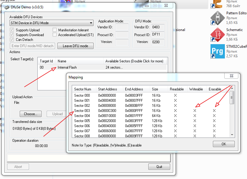
Carefully we look and we marvel that the flash down to the address 0x0800C000 is closed for recording and we write down this address, we will need it ...
By the way, I tried on the STM32F407VE, the memory is open for writing there with 0x08000000, i.e. From the very beginning ... why, in our version is not so, it is unclear, and did not dig, it was buried somewhere, but clearly not spelled out, is not comme il faut, because a large piece disappears without use ... maybe someone can tell where to dig ...
So, "haircut just started" ...
We need only two source files ...
We open them in the IDE and we rule ...
We take into account that CubeMX DOES NOT TOGETHER when the insert is regenerated between USER CODE BEGIN and USER CODE END ... there we will enter our add-ons ...
Let's start with main.c
on this with main.c all ...
go to usbd_conf.h and in
we bring to mind ...
go to usbd_dfu_it.c, then more ...
Actually, that's all ...
We connect the programmer, throw the jumpers into the programming mode, F7, F8 and botloader are recorded ...
You can use ...
Now we will prepare our application for boot through bootloder ...
Favorite application will blink LED ...
We are preparing and debugging the application, and changing certain places in the compiler and the program body to change the program launch address and interrupt vectors ...
Namely, in KEIL → Configure → Flash Tools

We change the address of the beginning of the program ...
We speak to generate HEX file

and changing the address of the vector table ...
collect the program F7 ...
the resulting HEX is converted into a dfo file by the Dfu file manager utility ...
specify our HEX file with the S19 or HEX button ... and click Generate ...
get the dfu file.
Actually, everything is ready.
Loading to controller ...
We connect our experimental card with the botloader already loaded to USB by setting the jumpers to DFU Mode.
You can control the appearance of STM Device in DFU Mode in the device list ...
run the "boot".

we point her our dfu file ...
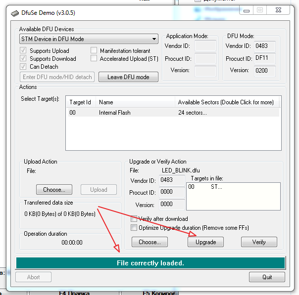
Click Upgrade and see the download result ... for sure, click verification.

all is well ... you can run ...
if the error got out, then the joint is somewhere ...
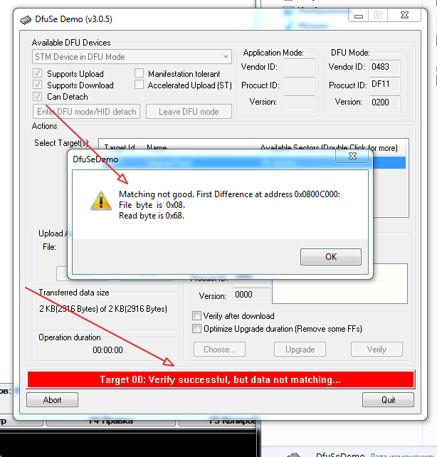
eg…
So, we will consider that everything is successful ... we switch the jumper to the application mode

and enjoy the blinking of the diode ...
...
Ufff. So much bukoffff. Tired copy-paste pictures :-)
Thank you for your attention ...
The great number of bootloaders found in the network, sometimes quite entertaining, are unfortunately “sharpened” for any particular crystal.
The proposed material contains the procedure for using the CubeMX package, the DfuSeDemo “downloads” and the Dfu file manager firmware preparation utilities, i.e., we abstract our hot hardware from the hardware, forgive me the macro assembler and datasheet.
Cooking environment ...
')
We need the actual CubeMX itself, the download of the DfuSeDemo + Dfu file manager, are in one package, the STM32 ST-LINK Utility, we are looking for everything on the STMicroelectronics website for free.
Our guinea pig with a STM32F103C8T6 chip from Uncle Liao
and the ST-Link programmer from there.
Well, your favorite IDE, in this particular presentation, we use KEIL, the compilation settings in other IDEs are not very different.
So let's go ...
Launch CubeMX and choose your crystal ...
We mark our Wishlist ...
In this particular task, we activate the USB device → Device FS and, accordingly, the USB Device → DownLoad Update Firmware class, and the RCC → High Speed Clock → Cristal / Ceramic Resonator is unforgettable on board.
Next, you need to select the bootloader mode switch, in this example, simply use the available jumper boot1.
We look at the scheme and, in accordance with it, boot1 is attached to the leg of PB2, so we will use it in the GPIO_Input mode.
Done, activate the Clock Configuration tab and start the configuration selection machine.
Jump to the Cofiguration tab ...
Choosing the GPIO button ...
And in the field ...
write a custom label, let it be boot1.
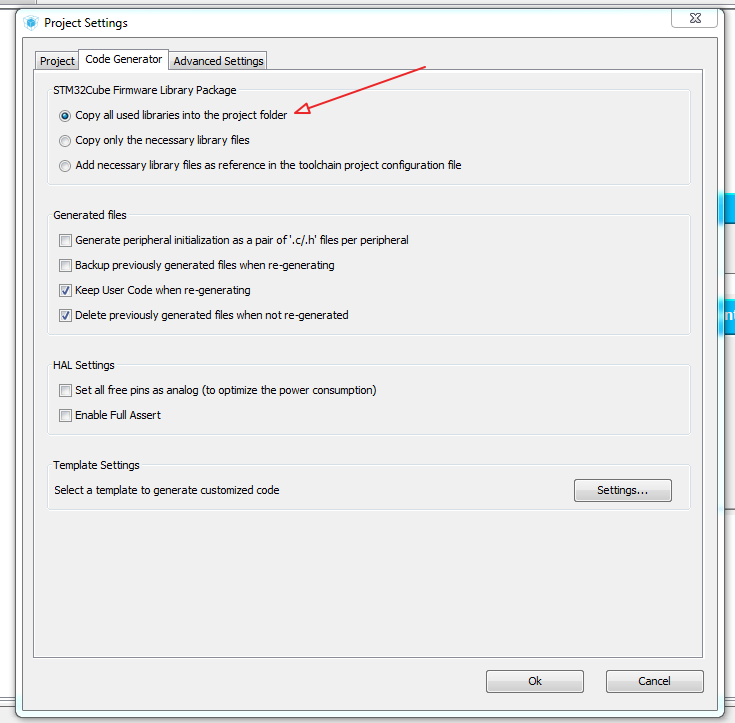
Next, set up the project ...
Choose Project → Setting ...
Choose and fill ...
Accordingly, we choose for which IDE a Cub to us will generate a project, in our case, MDK-ARM V5.
Bookmark the Code Generator in this embodiment will remain unchanged ...
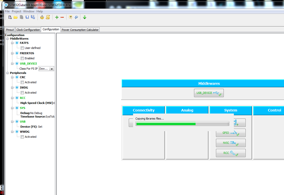
Well, that's all, run the generation of the project Project → Generate Code
When finished, Cub will offer to immediately launch your IDE ... how to proceed to choose you.
We start compilation and assembly and loading into a crystal ... F7, F8 ...
The end result ...
Switch the pins on our board to the operation mode and connect the USB cable ...
Open the control panel in Windows → system → device manager → USB controller. And we look at the list of devices, Windows silently rustles and installs the STM Device driver in DFU Mode (if it was not already installed).
So, the driver got up and decided, run the DfuSeDemo “bootloader” ...
We look at what a DFU Device has caught and click on the Select Target field ...
Carefully we look and we marvel that the flash down to the address 0x0800C000 is closed for recording and we write down this address, we will need it ...
By the way, I tried on the STM32F407VE, the memory is open for writing there with 0x08000000, i.e. From the very beginning ... why, in our version is not so, it is unclear, and did not dig, it was buried somewhere, but clearly not spelled out, is not comme il faut, because a large piece disappears without use ... maybe someone can tell where to dig ...
So, "haircut just started" ...
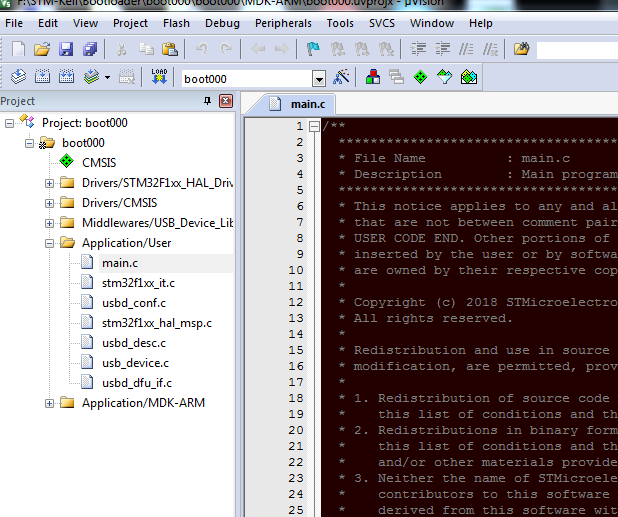
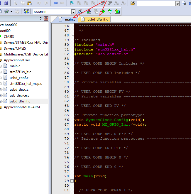
We need only two source files ...
We open them in the IDE and we rule ...
We take into account that CubeMX DOES NOT TOGETHER when the insert is regenerated between USER CODE BEGIN and USER CODE END ... there we will enter our add-ons ...
Let's start with main.c
/* USER CODE BEGIN PV */ /* Private variables ---------------------------------------------------------*/ typedef void (*pFunction)(void); pFunction JumpToApplication; uint32_t JumpAddress; /* USER CODE END PV */ . . . /* USER CODE BEGIN 0 */ uint32_t AddressMyApplicationBegin = 0x0800C000; uint32_t AddressMyApplicationEnd = 0x0800FBFC; /* USER CODE END 0 */ . . . /* USER CODE BEGIN 2 */ /* Check if the KEY Button is pressed */ if(HAL_GPIO_ReadPin(boot1_GPIO_Port, boot1_Pin ) == GPIO_PIN_SET) { /* Test if user code is programmed starting from address 0x0800C000 */ if (((*(__IO uint32_t *) USBD_DFU_APP_DEFAULT_ADD) & 0x2FFE0000) == 0x20000000) { /* Jump to user application */ JumpAddress = *(__IO uint32_t *) (USBD_DFU_APP_DEFAULT_ADD + 4); JumpToApplication = (pFunction) JumpAddress; /* Initialize user application's Stack Pointer */ __set_MSP(*(__IO uint32_t *) USBD_DFU_APP_DEFAULT_ADD); JumpToApplication(); } } MX_USB_DEVICE_Init(); /* */ /* USER CODE END 2 */ . . . on this with main.c all ...
go to usbd_conf.h and in
#define USBD_DFU_APP_DEFAULT_ADD 0x0800000 we bring to mind ...
#define USBD_DFU_APP_DEFAULT_ADD 0x080C000 // … go to usbd_dfu_it.c, then more ...
. . . /* USER CODE BEGIN PRIVATE_TYPES */ extern uint32_t AddressMyApplicationBegin; extern uint32_t AddressMyApplicationEnd; /* USER CODE END PRIVATE_TYPES */ . . . /* USER CODE BEGIN PRIVATE_DEFINES */ #define FLASH_ERASE_TIME (uint16_t)50 #define FLASH_PROGRAM_TIME (uint16_t)50 /* USER CODE END PRIVATE_DEFINES */ . . . , «» … uint16_t MEM_If_Init_FS(void) { /* USER CODE BEGIN 0 */ HAL_StatusTypeDef flash_ok = HAL_ERROR; // while(flash_ok != HAL_OK){ flash_ok = HAL_FLASH_Unlock(); } return (USBD_OK); /* USER CODE END 0 */ } . . . uint16_t MEM_If_DeInit_FS(void) { /* USER CODE BEGIN 1 */ HAL_StatusTypeDef flash_ok = HAL_ERROR; // flash_ok = HAL_ERROR; while(flash_ok != HAL_OK){ flash_ok = HAL_FLASH_Lock(); } return (USBD_OK); /* USER CODE END 1 */ } . . . uint16_t MEM_If_Erase_FS(uint32_t Add) { /* USER CODE BEGIN 2 */ uint32_t NbOfPages = 0; uint32_t PageError = 0; /* Variable contains Flash operation status */ HAL_StatusTypeDef status; FLASH_EraseInitTypeDef eraseinitstruct; /* Get the number of sector to erase from 1st sector*/ NbOfPages = ((AddressMyApplicationEnd - AddressMyApplicationBegin) / FLASH_PAGE_SIZE) + 1; eraseinitstruct.TypeErase = FLASH_TYPEERASE_PAGES; eraseinitstruct.PageAddress = AddressMyApplicationBegin; eraseinitstruct.NbPages = NbOfPages; status = HAL_FLASHEx_Erase(&eraseinitstruct, &PageError); if (status != HAL_OK) { return (!USBD_OK); } return (USBD_OK); /* USER CODE END 2 */ } . . . uint16_t MEM_If_Write_FS(uint8_t *src, uint8_t *dest, uint32_t Len) { /* USER CODE BEGIN 3 */ uint32_t i = 0; for(i = 0; i < Len; i+=4) { /* Device voltage range supposed to be [2.7V to 3.6V], the operation will be done by byte */ if(HAL_FLASH_Program(FLASH_TYPEPROGRAM_WORD, (uint32_t)(dest+i), *(uint32_t*)(src+i)) == HAL_OK) { // Usart1_Send_String("MEM_If_Write_FS OK!"); /* Check the written value */ if(*(uint32_t *)(src + i) != *(uint32_t*)(dest+i)) { /* Flash content doesn't match SRAM content */ return 2; } } else { /* Error occurred while writing data in Flash memory */ return (!USBD_OK); } } return (USBD_OK); /* USER CODE END 3 */ } . . . uint8_t *MEM_If_Read_FS (uint8_t *src, uint8_t *dest, uint32_t Len) { /* Return a valid address to avoid HardFault */ /* USER CODE BEGIN 4 */ uint32_t i = 0; uint8_t *psrc = src; for (i = 0; i < Len; i++) { dest[i] = *psrc++; } return (uint8_t*)(dest); /* , */ /* USER CODE END 4 */ } . . . uint16_t MEM_If_GetStatus_FS (uint32_t Add, uint8_t Cmd, uint8_t *buffer) { /* USER CODE BEGIN 5 */ switch (Cmd) { case DFU_MEDIA_PROGRAM: buffer[1] = (uint8_t)FLASH_PROGRAM_TIME; buffer[2] = (uint8_t)(FLASH_PROGRAM_TIME << 8); buffer[3] = 0; break; case DFU_MEDIA_ERASE: default: buffer[1] = (uint8_t)FLASH_ERASE_TIME; buffer[2] = (uint8_t)(FLASH_ERASE_TIME << 8); buffer[3] = 0; break; } return (USBD_OK); /* USER CODE END 5 */ } Actually, that's all ...
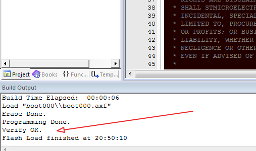
We connect the programmer, throw the jumpers into the programming mode, F7, F8 and botloader are recorded ...
You can use ...
Now we will prepare our application for boot through bootloder ...
Favorite application will blink LED ...
We are preparing and debugging the application, and changing certain places in the compiler and the program body to change the program launch address and interrupt vectors ...
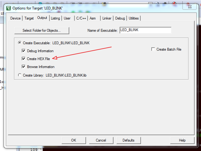
Namely, in KEIL → Configure → Flash Tools
We change the address of the beginning of the program ...
We speak to generate HEX file
and changing the address of the vector table ...
collect the program F7 ...
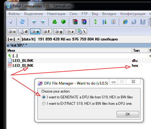
the resulting HEX is converted into a dfo file by the Dfu file manager utility ...
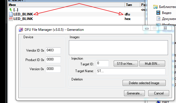
specify our HEX file with the S19 or HEX button ... and click Generate ...
get the dfu file.
Actually, everything is ready.
Loading to controller ...
We connect our experimental card with the botloader already loaded to USB by setting the jumpers to DFU Mode.
You can control the appearance of STM Device in DFU Mode in the device list ...
run the "boot".
we point her our dfu file ...
Click Upgrade and see the download result ... for sure, click verification.
all is well ... you can run ...
if the error got out, then the joint is somewhere ...
eg…
So, we will consider that everything is successful ... we switch the jumper to the application mode
and enjoy the blinking of the diode ...
...
Ufff. So much bukoffff. Tired copy-paste pictures :-)
Thank you for your attention ...
Source: https://habr.com/ru/post/432398/
All Articles