Implementation of a Simple Ternary System
Three-valued Logic
List of accomplishments
- Basic ternary logic gates: T_NOT, T_OR, T_AND, T_NAND, T_NOR, T_XOR and more
- Synthesis, Minimization and Realization for Ternary Functions
- Ternary half adder, Ternary full adder, Ternary ripple carry adder
- Ternary full subtractor, comparator, multiplier, multiplexer / demultiplexer
- Ternary flip flap flops and latches
- A primitive Ternary Arithmetic and Logical Unit (ALU)
Conventions and used technologies
- Unbalanced Ternary (0, 1, 2) was used in implementation
- 1 Trit is expressed by 2 Bits: 0 ~ 00, 1 ~ 01, 2 ~ 10 (11 is undefined)
- ModelSim, Quartus prime, Logisim
Introduction
As a first-year student of Innopolis University, we have It was a ternary system with basic components (gates).
In the three-valued logic (also trinary logic, trivalent, ternary), it is not a rule.
Ternary logic is MVL (Multi-valued logic) compliant. However, only three logic states are used, ' 0 ', ' 1 ' and ' 2 '. The logarithm ( e ) is the optimum radix ( r ). Compared to binary logic, which uses r = 2 , it means that it is not a problem. designers to build a ternary computer.
Nikolai Brusentsov and his colleagues at the Moscow State University in 1958. Setun ,
Ternary logic
A ternary logic function is a mapping F: {0,1,2} n -> {0,1,2} . Of binary logic over binary logic.
For example, the number of distinct operators is 27 Similarly, where the Boolean logic has 2 2 2 = 16, there is a distinct binary operator (terrestrial logic has 3 3 2 = 19,683 such operators. Where it can be easily defined as a significant number of operators, nor, exclusive or equivalence, implication, ternary operators.
Advantages of Ternary Logic
A ternary logic representation and more compact comparing than the equivalent binary logic representation. It is possible to make combinations, then it makes it possible to complete the circuit.
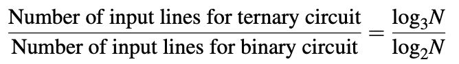


Binary binary code should not be reduced to 0.63 times.
Disadvantages of Ternary Logic
Although it is not a practical choice, it is not a practical choice. The reasons are
- Theoretical test, simulation, and test levels
- Representing three ternary logic levels (0, 1, and 2)
- No computational model and programming language is developed. However, it has been possible to choose a resonant tunneling diode (RTD), a resonant tunneling diode (RTD) and a carbon nanoscale semiconductor (CMOS), demonstrating that it was a choice.
Various possible representations for the ternary system
- Ternary numeral system (Unbalanced ternary) , each digit is a trit (trinary digit) having a value of: 0, 1, or 2
- Balanced ternary , each digit has one of 3 values: −1, 0, or +1; these values may also be simplified to -, 0, +, respectively (most commonly used)
- Redundant binary representation , the number of 1, 0, 0/1 (the value 0/1 has two different representations)
- Skew binary number system , non-zero digit has a value of 2, and the remaining digits have a value of 0 or 1
More about the balanced Ternary Numbering System
Today, mostly all hardware is designed for binary computing. If you’ve turned to ternary computing. However, this is not the truth today. The balanced ternary radix notation has some beneficial properties:
- Ternary inversion is easy, just exchange −1 with 1 and vice versa. If we use an example, it’s 24 T 1 in tantrum, and -24 as T10 in balanced ternary notation (t is simply a notation for -1). This is a simpler rule for the two's complement in binary logic.
- The most significant nonzero 'trit'
- It is identical to truncation.
- Addition and subtraction are the same as the operation (I just add the digits using the rules for addition of digits)
Examples:
21 10 = 1T10 3 ; 296 10 = 11T00T 3 ;
-24 10 = T10 3 ; -137 10 = T110T1 3
Ternary arithmetics
It can be seen that it can be a ternary switch.
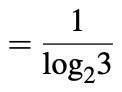
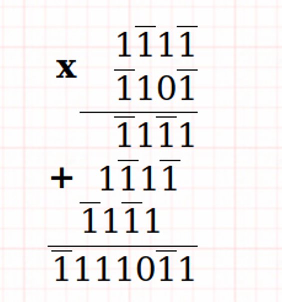
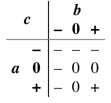
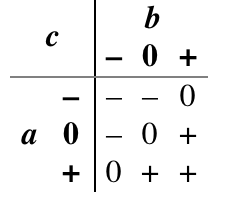
Balanced Ternary Addition and Multiplication
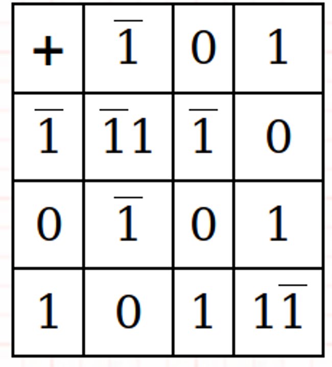
Examples: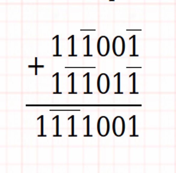
Ternary combinational circuits (Ternary gates)
A combinational circuit is gates and output variables. The output of the circuit depends only upon the present input. Variables and generate output signals. This process transforms ternary information from
ternary output data.
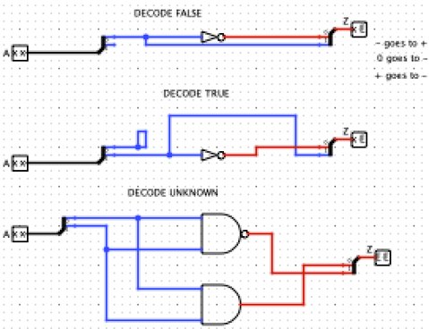
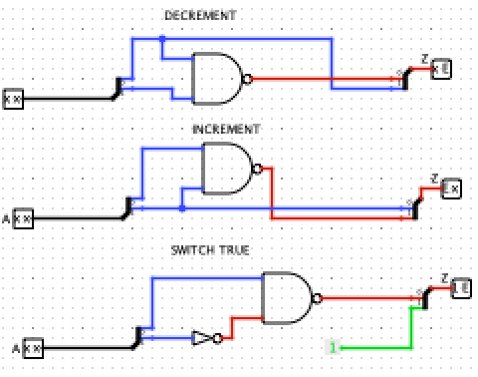
If you’re talking about it, you can easily, or, or, nand, nor, exclusive or, equivalence, implication ternary operators. We will consider the following ternary circuits:
If you are, you’ll find out if you want to do so.
It can be used if you want to make it true or not.
Consensus : Investigation There are several natural extensions. If you are true, you can always
If you know, it’s not a question. Otherwise, it jumps to any input.
Inversion of logic modulo 2 and the modulation of the modulation.
Synthesis, Minimization and Realization for Ternary Functions
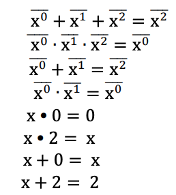
Relationships interrelated in the ternary logic system
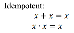
A ternary logic of a Max-Min expression. Ternary Max-Min Expressions are defined as follows:
Variable : Any symbol of the set T ∈ {0,1,2} is a ternary variable.
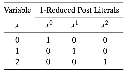
Literal : Literals are transformed forms of a variable. They are used to form Max-Min expressions.
In the literature, the two types of literals are commonly used: 1-reduced post literals and 2-reduced post literals. This is a variable x, where i ∈ {0,1,2}. When x = i, then x i = 1, otherwise x i = 0. The variable is shown below.
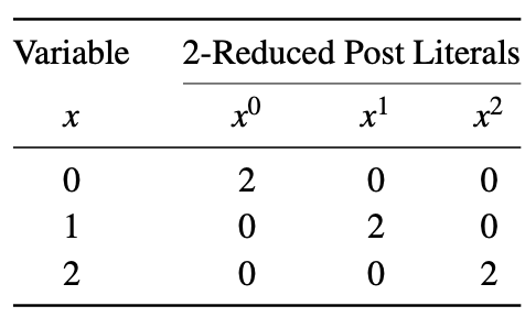
This is a variable x, where i ∈ {0,1,2}. When x = i, then x i = 2, otherwise x i = 0. The variable is shown below. Maxim Minor expressions as discussed previously.
Minterm : When the function is combined, then the term is called a minterm. For example, for a 3-variable ternary logic function (x, y, z), xyz and xz are two examples of minterms.
Max-Min Expression : This is a combination of max-min expressions. For example, for a 3-variable ternary logic function F (x, y, z) = xy + yz + xyz.
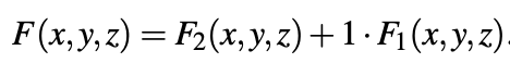
Any function F (x, y, z) can always be represented as
To minimize ternary functions are:
- Manipulation of algebra expression as in Boolean algebra.
- The tabular method.
- Ternary K. map method.
It is necessary to convert the ternary variable into unary variable (using the 2-Reduced Post Literals table).
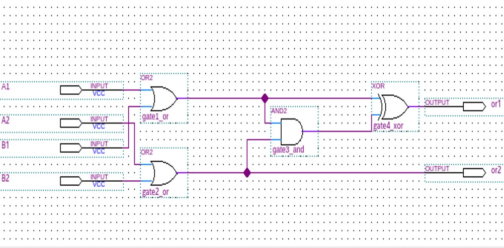
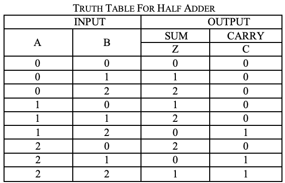
Ternary half adder
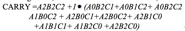
A trit numbers is a half adder. the circuit does not consider carry carried in the previous addition. The addition process in ternary logic system is shown below. Here are the two inputs and sum (S) and carry (CARRY)
are two outputs.
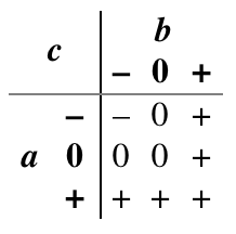
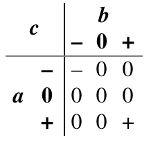
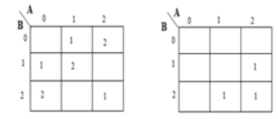
Analysis
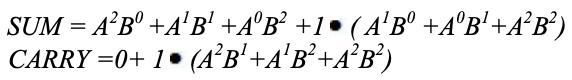
A karnaugh map (K-map) is used to represent the sum and carry output. K-maps are useful for logic circuits. Here is a K-map of 2 inputs is used. Since no grouping of 2's is possible, the output equation is as below.
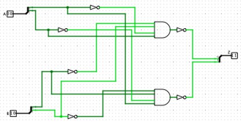
Implementation
module half_adder ( input [1:0] A, [1:0] B, output [1:0] sum, [1:0] carry ); wire [1:0] temp = 2'b01; wire [1:0] a0, a1, a2, b0, b1, b2; wire [1:0] i0, i1, i2, i3, i4, i5; wire [1:0] o0, o1, o2, o3, o4; wire [1:0] c0, c1, c2, c3; mask msk_1(A, a0, a1, a2); mask msk_2(B, b0, b1, b2); andgate and_1(a2,b0,i0); andgate and_2(a1,b1,i1); andgate and_3(a0,b2,i2); // partial products orgate or_1(i0, i1, o0); orgate or_2(o0, i2, o1); // f1 andgate and_4(a1,b0,i3); andgate and_5(a0,b1,i4); andgate and_6(a2,b2,i5); // partial products orgate or_3(i3, i4, o2); orgate or_4(o2, i5, o3); // f2 andgate and_7(o3,temp,o4); // 1.f2 andgate andc_0(a2,b1,c0); andgate andc_1(a1,b2,c1); orgate orc_0(c0,c1,c2); orgate orc_1(c2,i5,c3); andgate andc_2(c3,temp,carry); // carry orgate or_5(o1, o4, sum); // sum endmodule Ternary full adder
For example, it can be described the following:
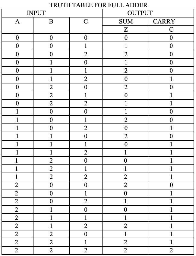
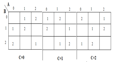
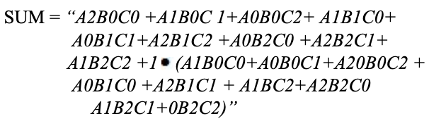
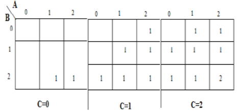
Analysis
A karnaugh map (K-map) is used to represent the sum and carry output. K-maps are useful for logic circuits. Here is a K-map of 3 inputs is used.
Implementation
module ternary_full_adder ( input [1:0] A, [1:0] B, [1:0] c_in, output [1:0] sum, [1:0] c_out ); wire [1:0] temp1 = 2'b01; wire [1:0] temp2 = 2'b00; wire [1:0] a0, a1, a2, b0, b1, b2, a20; wire [1:0] i0, i1, i2, i3, i4; wire [1:0] i5, i6, i7, i8, i9, i10, i11, i12, i13, i14, i15, i16, i17; wire [1:0] o0, o1, o2, o3, o4, o5, o6, o7, o8, o9; wire [1:0] c0, c1, c2; wire [1:0] h0, h1, h2, h3, h4, h5, h6, h7; wire [1:0] t0, t1, t2, t3, t4, t5, t6, t7, t8, t9, t10, t11, t12, t13, t14, t15, t16; wire [1:0] g0, g1, g2, g3, g4, g5, g6, g7, g8, g9, g10, g11, g12, g13, g14, g15; mask mk_1(A, a0, a1, a2); mask mk_2(B, b0, b1, b2); mask mk_3(c_in, c0, c1, c2); andgate3 and3_1(a2,b0,c0, i0); andgate3 and3_2(a1,b0,c1, i1); andgate3 and3_3(a0,b0,c2, i2); andgate3 and3_4(a1,b1,c0, i3); andgate3 and3_5(a0,b1,c1, i4); andgate3 and3_6(a2,b1,c2, i5); andgate3 and3_7(a0,b2,c0, i6); andgate3 and3_8(a2,b2,c1, i7); andgate3 and3_9(a1,b2,c2, i8); andgate3 and3_10(a1,b0,c0, i9); andgate3 and3_11(a0,b0,c1, i10); orgate or__(a2, a0, a20); andgate3 and3_12(a20,b0,c2, i11); // note a20 andgate3 and3_13(a0,b1,c0, i12); andgate3 and3_14(a2,b1,c1, i13); andgate3 and3_15(a1,B,c2, i14); andgate3 and3_16(a2,b2,c0, i15); andgate3 and3_17(a1,b2,c1, i16); andgate3 and3_18(temp2,b2,c2, i17); orgate or_1(i9, i10, o0); orgate or_2(o0, i11, o1); orgate or_3(o1, i12, o2); orgate or_4(o2, i13, o3); orgate or_5(o3, i14, o4); orgate or_6(o4, i15, o5); orgate or_7(o5, i16, o6); orgate or_8(o6, i17, o7); andgate and_1(o7, temp1, o8); // 1.f2 orgate or_9(i0, i1, h0); orgate or_10(h0, i2, h1); orgate or_11(h1, i3, h2); orgate or_12(h2, i4, h3); orgate or_13(h3, i5, h4); orgate or_14(h4, i6, h5); orgate or_15(h5, i7, h6); orgate or_16(h6, i8, h7); orgate or_17_(h7, o8, sum); // sum // carry andgate3 and3_19(a2,b2,c2, t0); // f1 andgate3 and3_20(a0,b1,c2, t1); andgate3 and3_21(a0,b2,c2, t2); andgate3 and3_22(a0,b2,c1, t3); andgate3 and3_23(a1,b2,c0, t4); andgate3 and3_24(a2,b2,c0, t5); andgate3 and3_25(a1,b1,c1, t6); andgate3 and3_26(a1,b2,c1, t7); andgate3 and3_27(a1,b0,c2, t8); andgate3 and3_28(a1,b1,c2, t9); andgate3 and3_29(a1,b2,c2, t10); andgate3 and3_25_(a2,b0,c2, t11); andgate3 and3_26_(a2,b1,c2, t12); andgate3 and3_27_(a2,b0,c1, t13); andgate3 and3_28_(a2,b1,c1, t14); andgate3 and3_29_(a2,b2,c1, t15); andgate3 and3_9_(a2,b1,c0, t16); orgate or_17(t1, t2, g0); orgate or_18(g0, t3, g1); orgate or_19(g1, t4, g2); orgate or_20(g2, t5, g3); orgate or_21(g3, t6, g4); orgate or_22(g4, t7, g5); orgate or_23(g5, t8, g6); orgate or_24(g6, t9, g7); orgate or_25(g7, t10, g8); orgate or_21_(g8, t11, g9); orgate or_22_(g9, t12, g10); orgate or_23_(g10, t13, g11); orgate or_24_(g11, t14, g12); orgate or_25_(g12, t15, g13); orgate or_5_(g13, t16, g14); //f2 andgate and_2(g14, temp1, g15); // 1.f2 orgate or_26(g15, t0, c_out); // carry endmodule Ternary Full Subtractor
Ternary full-subtractor Truth table for Subtractor is shown below
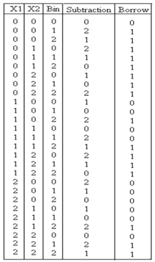
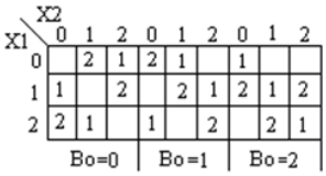
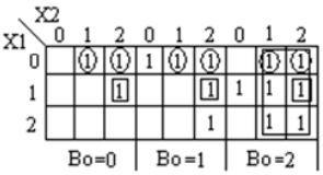
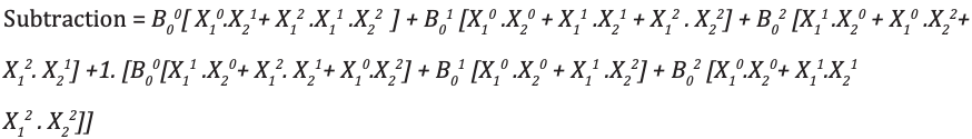

module full_subtractor( input [1:0] P, Q, b_in, output [1:0] diff, b_out ); wire [1:0] temp1 = 2'b01; wire [1:0] temp2 = 2'b10; wire [1:0] a0, a1, a2, b0, b1, b2; wire [1:0] i0, i1, i2, i3, i4, i5, i6, i7, i8, i9, i10, i11, i12, i13, i14, i15, i16, i17; wire [1:0] c0, c1, c2, c3; wire [1:0] h0, h1, h2, h3, h4, h5, h6, h7, h8, h9, h10, h11; wire [1:0] t0, t1, t2, t3, t4, t5, t6, t7, t8, t9; wire [1:0] p0, p1, p2; wire [1:0] q0, q1, q2; mask mk_1(P, p0, p1, p2); mask mk_2(Q, q0, q1, q2); mask mk_3(b_in, b0, b1, b2); andgate and_0(p0, q1, i0); andgate3 and3_0(p2, p1, q2, i1); orgate or_0(i0, i1, i2); andgate and_1(b0, i2, i3); // first expression andgate and_2(p0, q0, i4); andgate and_3(p1, q1, i5); andgate and_4(p2, q2, i6); orgate or_1(i4, i5, i7); orgate or_2(i7, i6, i8); andgate and_5(i8, b1, i9); // second expression andgate and_6(p1, q0, i10); andgate and_7(p0, q2, i11); andgate and_8(p2, q1, i12); orgate or_3(i10, i11, i13); orgate or_4(i13, i12, i14); andgate and_9(i14, b2, i15); // third expression orgate or_5(i3, i9, i16); orgate or_6(i16, i15, c0); //f1 orgate or_7(i10, i12, t0); orgate or_8(t0, i11, t1); andgate and_10(t1, b0, t2); // 1 expression andgate and_11(p1, q2, i17); orgate or_9(i4, i17, t3); andgate and_12(t3, b1, t4); // 1- expression orgate or_10(i4, i5, t5); orgate or_11(t5, i6, t6); andgate and_12_(t6, b2, t7); // 1-- expression orgate or_12(t2, t4, t8); orgate or_13(t8, t7, t9); andgate and_13(t9, temp1, c1); orgate or_14(c0, c1, diff); // difference orgate or_15(q1, q2, h0); andgate and_14(h0, temp2, h1); andgate and_15(h1, b2, h3); // 1 b orgate or_16(i0, i11, h4); andgate and_16(h4, temp2, h5); // 1- b andgate and_17(i17, temp2, h6); // 1-- b andgate3 and3_1(p2, q2, b1, h7); // 1--- b andgate3 and3_2(p1, q0, b2, h8); // 1---- b orgate or_17(h3, h5, h9); orgate or_18(h9, h6, h10); orgate or_19(h10, h7, h11); orgate or_20(h11, h8, b_out); // borrow endmodule Ternary ripple carry adder
Ripple-carry adder (RCA) is a well-known circuit for ternary full adders. Ternary RCA is a binary counterpart. A Ternary Half Adder is employed to add the least sign of the Ternary digits. The rest are summed up by Ternary Full Adders. As mentioned before, Ternary adds three variables.
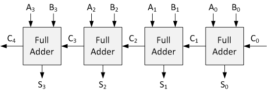
Implementation
module ternary_ripple_adder ( input [15:0] input1 , input [15:0] input2 , output [15:0] out , output [1:0] overflow_trit ); wire [15:0] carry ; reg tem; assign carry[0] = tem; assign carry[1] = tem; always @(input1, input2) begin tem <= 1'b0; end generate genvar i; for (i = 0; i <= 12; i=i+2) begin full_add af({input1[i+1],input1[i]}, {input2[i+1],input2[i]}, {carry[i+1],carry[i]}, {out[i+1], out[i]}, {carry[i+3],carry[i+2]}); end full_add af({input1[15],input1[14]}, {input2[15],input2[14]}, {carry[15],carry[14]}, {out[15], out[14]}, overflow_trit); endgenerate endmodule Ternary comparators
Ternary comparator circuit camper two inputs X 1 , X 2 and therefore generates output as X 1 = X 2 , X 1 > X 2 , X 1 <X 2 . Truth table for a ternary comparator is shown below
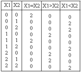
Output equation for X 1 = X 2 , X 1 > X 2 , X 1 <X 2 are:
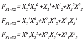
Corresponding k-maps are shown below
module ternary_comparators ( input [1:0] x1, x2, output [1:0] f1, f2, f3 ); wire [1:0] t0, t1, t2, t3, t4, t5, t6, t7; wire [1:0] h0, h1, h2, h3, h4, h5; wire [1:0] x10, x11, x12; wire [1:0] x20, x21, x22; mask mk_1(x1, x10, x11, x12); mask mk_2(x2, x20, x21, x22); andgate and_0(x10, x20, t0); andgate and_1(x22, x22, t1); orgate or_0(t0, t1, h0); orgate or_1(h0, x11, h1); orgate or_2(h1, x21, f1); // x1 == x2 andgate and_2(x11, x20, t2); andgate and_3(x12, x20, t3); andgate and_4(x12, x21, t4); orgate or_3(t2, t3, h3); orgate or_4(h3, t4, f2); // x1>x2 andgate and_5(x10, x21, t5); andgate and_6(x10, x22, t6); andgate and_7(x11, x22, t7); orgate or_5(t5, t6, h4); orgate or_6(h4, t7, f3); // x1<X2 endmodule Ternary multiplier
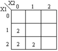
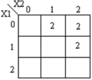
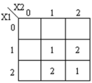
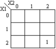
The ternary multiplier is a circuit that multiplies the number of the corresponding product. Truth table for this circuit is shown below:
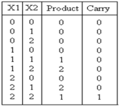
The following is the expression for the product and carry are shown:
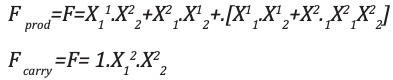
The corresponding K-maps are shown:
')
module ternary_multiplier ( input [1:0] A, [1:0] B, output [1:0] product, [1:0] carry ); wire [1:0] temp = 2'b01; wire [1:0] a0, a1, a2, b0, b1, b2; wire [1:0] i0, i1, i2, i3, i4, i5; wire [1:0] o0, o1, o2, o3, o4; mask msk_1(A, a0, a1, a2); mask msk_2(B, b0, b1, b2); andgate and_1(a1,b2,i0); andgate and_2(a2,b1,i1); orgate or_1(i0, i1, o0); // f1 andgate and_4(a1,b1,i3); andgate and_5(a2,b2,i4); orgate or_3(i3, i4, o2); andgate and_3(temp,o2,o3); orgate or_4(o3, o0, product); // product andgate andc_0(a2,b2,o4); andgate andc_1(temp,o4,carry); // carry endmodule Ternary Multiplexers and Demultiplexers
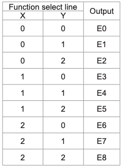
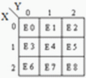
Multiplexer is a circuit output. It is also known as decoder. The output of the function of the multiplexer is determined by the number of function lines. Thus for 2 trit
multiplexer the output will be 3 2 = 9 and two will be the function select lines. Multiplexer ie function
selection logic 1 out of 9 functions as an output. Function select logic is implemented using logic gates. The output equation of function selection logic is:

Demultiplexer is also referred to as encoder. Its functionality is reverse to that of multiplexer. Several outputs
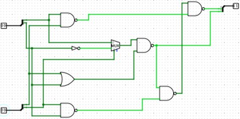
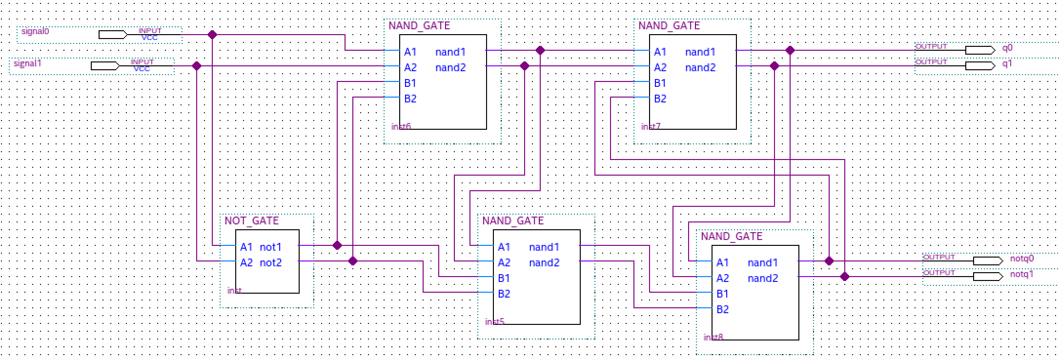
Simple Ternary D Latch
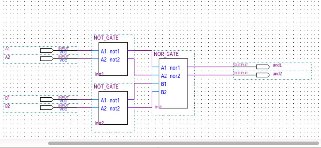
Although it is a straightforward design of circuits, it has been challenged. However, the NOR or NAND gates were used with the corresponding ternary tatch.
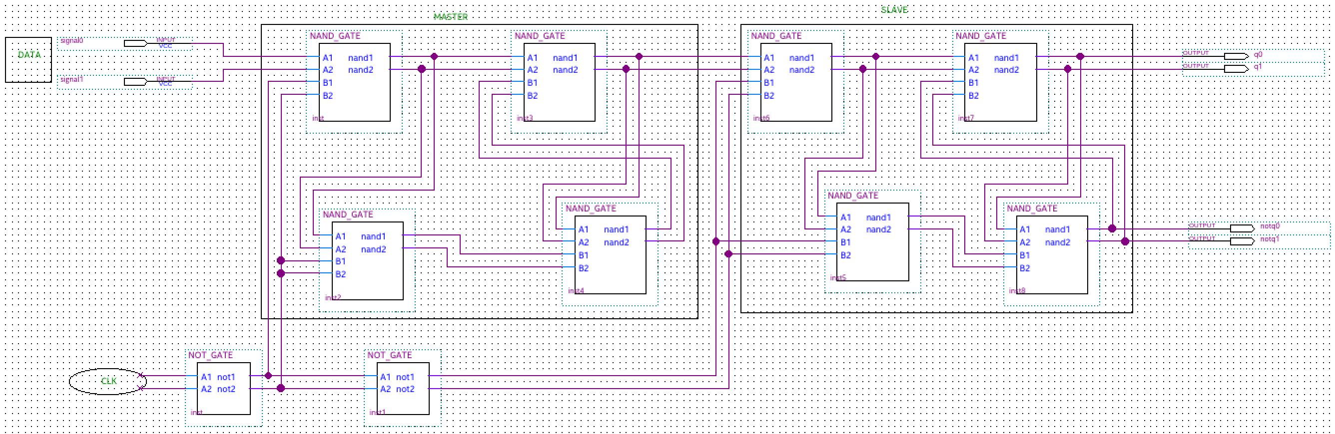
Simple Ternary D Flip-Flap-Flop
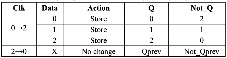
The Master Slave (MS) ternary D Flip-Flap-Flop (FFF) is realized on the ternary D latches. Flip-Flop (FF) is realized using binary D latches. MS binary flip-flop images are well known. In order to implement the MSDFFF, we’ll replace the binary ches DSC ter ches realized realized realized realized realized realized (inputs inputs inputs inputs inputs inputs inputs inputs inputs inputs inputs inputs inputs inputs inputs inputs)) NAND circuits and ternary STI circuits are shown

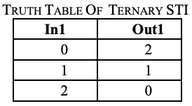
For the MSDFFF with the digital clock, the data are ternary (0, 1 and 2 logic)
implementation, 0 and 2 logic). The MS ternary D FFF with
binary clock can be read
high (positive edge) or low to low (negative edge), depending
on the number of STIs.
The inputs are the Q and Not_Q. Signal line

1-bit Ternary Arithmetic and Logic Unit (T-ALU)
Ternary Arithmetic Logic Unit (ALU). This represents the ternary computer The ALU carries out the arithmetic operations like, subtraction, multiplication, multiplication, NIC, NOR, NOT, AND, and OR. Below is shown in a trit ALU
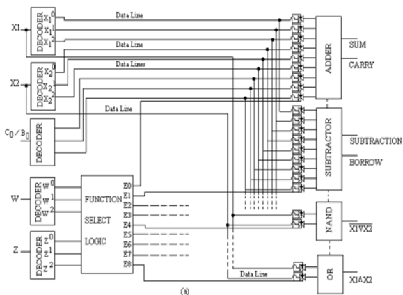
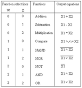

ALU are decoders, function select logic (Multiplexer), transmission gate and separate processing modules. It is a function of choice of functions for the selection of functions.
TG (Ternary gate) are associated with each module. Any module associated with data lines. For example, it can be used as the pathway.
Adder modules while there are lines of data.
Finally, ALU can be formed.
Source: https://habr.com/ru/post/431726/
All Articles