The optimal temperature in the house or how to install the thermostat in the far room without wires

For many, it is far from a secret that such devices as weekly thermostats help to ensure the optimum room temperature in the house, in addition to saving energy resources spent on heating. For the correct operation of the device it is usually placed in the farthest room, where the lowest temperature. But most thermostats assume a wired connection to the boiler for control and it is not always possible to lay these wires. About the solution of this problem and will be discussed in this article. Anyone who is interested in asking under the cat ...
I had to face a similar task. The design of my house is quite elongated, and the thermostat was installed correctly, I had to stretch over 50 m of cable through the rooms with the repairs already made, the alternative was to lay the facade, but I immediately discarded it. Moreover, it was also problematic to start the cable from the street to the boiler, and I didn’t want to spoil the appearance of the facade with another wire, without that it was enough. The boiler itself is installed in the kitchen and the location of the thermostat next to it was a bad idea. As a result, I came to the conclusion that the thermostat must still be moved to the far room, and the signal transmitted over the radio channel. The process of developing my next crafts began as usual with the formulation of the problem. So let's start ...
TK
We define the requirements for the device to solve the problem.
- The device design should be small-sized and placed in an aesthetic case of white or black color.
- The receiver and transmitter modules must be powered by a pair of AA batteries.
- The life of the modules from one set of batteries must be at least one year.
- The connection to the thermostat and the gas boiler must be carried out by standard interfaces without making any changes to the design.
- Devices must be assembled at an affordable element base from local suppliers.
Hardware
When the main requirements have been determined, we proceed to the design. Let's start with the hardware.
Based on the TOR, the main requirements for the element base will be: the ability to work in the voltage range from 1.8 to 3 volts. And also the ability to go to sleep, or off the periphery at a time when it is not needed. I decided to start my choice by choosing a transceiver. I considered the simplest solutions in the form of modules MX-FS-03V and MX-05V, the price is of course very attractive, but the quality of work on reviews is horror, and the communication range is not so hot. And in my case, it was necessary to transmit the signal through 4 walls. In addition, it was originally intended to confirm the dispatch, so that the connection was needed two-way, which would require two sets. LoRa modules and various modules of the HC series were also considered. The assortment was still limited to what they sell locally. As a result, having considered all the available options, I decided to opt for the ready-made SI4432 modules. In terms of price-opportunity in my opinion, they were the best.
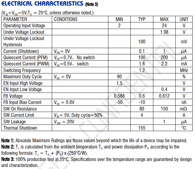
This module has extensive technical capabilities and is also very economical with correctly selected settings. The ability to control the output power is also very useful, because You can choose the best, thereby reducing the energy consumption of the batteries. Here is a table with characteristics from the documentation.
')
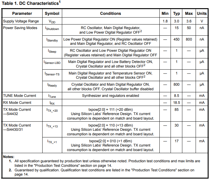
Let us consider in more detail the indicators of energy consumption in various modes from the table. We will need this data later to calculate the battery life of devices.
In our case, the use of the Sleep mode is already acceptable, not to mention the complete shutdown by the Shutdown function.
Initially, I planned to use ATMega 8 as a central processor, but after studying the documentation in more detail, I realized that it does not fall into my supply voltage range. As a result, I chose the ATMega 328P, since she fully met all my requirements. Looking ahead, I will say that the fact that I found a ready bootloader for her also played in her favor, but more on that later.
Let us consider in more detail the selected controller in terms of power consumption and core clocking.
Let's first deal with clocking. Since we have an operating voltage range of up to 3 volts, then the choice of quartz resonator is also limited here, and the following graph tells us so
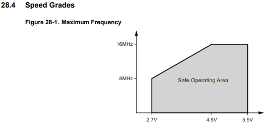
As we see at 8 MHz, we will not get a stable work, therefore, we will use quartz at 4 MHz.
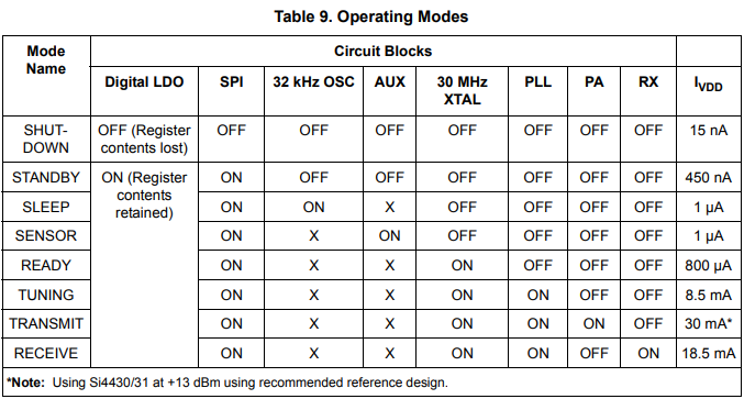
Now let's consider power consumption in various operating modes. Here is a table of documentation describing the characteristics of energy consumption.
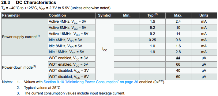
Thus, if you switch the controller to Power-Down mode, the consumption of the microcontroller itself is reduced to 44 uA, with certain reservations of course.
In addition to the elements already selected, we will add a red indicator LED with a working current of 1 mA.
This is where the common components for the receiver and transmitter end.
Consider additional components for the receiver.
At the output of an ordinary room thermostat, a relay contact with a good switching capacity (250 V 5 A), so it does not matter to him what to control, therefore, according to the terms of the TOR, there must be the same relay output in our receiver. But how to ensure low power consumption of the relay in on mode, because the coil of even the smallest relay consumes ten milliamperes, and the factory thermostat from one set of normal batteries works without exaggeration for at least 2 heating seasons. I was thinking about this task for a couple of days, and suddenly, during the repair of one of the devices, it dawned on me; And why during the repair, but because they are used in the repaired device. This type of relay is able to maintain its state for an infinite time without energy consumption. In order for the relay to change its state, it is sufficient to apply a pulse to the required coil, in the case of two winding relays, or a pulse in reverse polarity, in the case of a relay with one winding. Thus, with the type of relay decided, but what to do with a particular model? After a little searching on the Internet I came to the conclusion that it would be a problem for me to get a low voltage relay for me, I had to dwell on the 24 V relays I had at Takamisawa ALD24W-K. But this decision gave rise to a new problem - where to get 24 V?
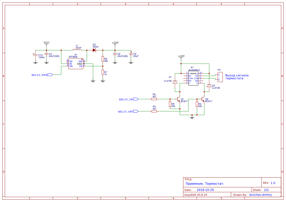
The answer was found quickly, perhaps it is not the most correct, but still. I decided to install a step-up converter and raise the voltage to 20 V, which is quite enough for confident switching of the relay. The converter is taken from a fairly common module based on MT3608. This is a working solution that I have tested more than once, including the design of an electric screwdriver (you can read about it here on Habré). EN output allows you to control the operation of the converter, which significantly reduces power consumption. Actually, here is the data from the documentation.
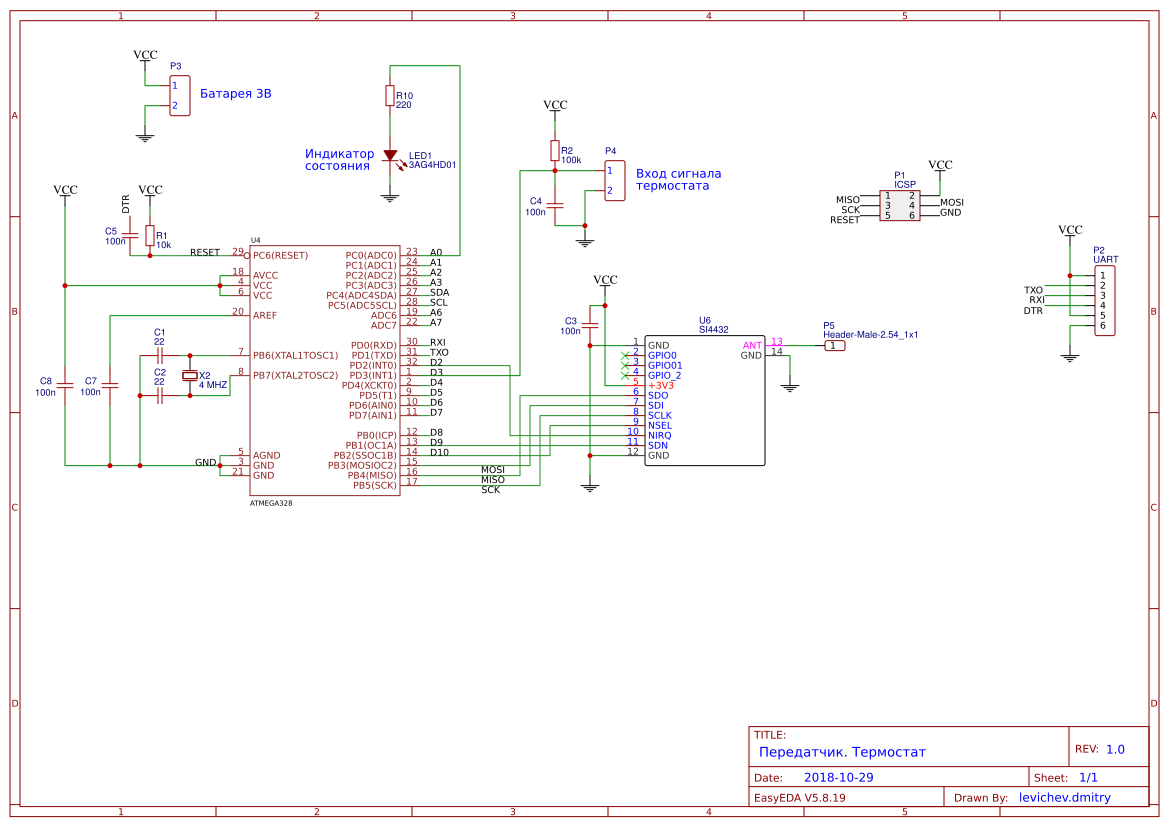
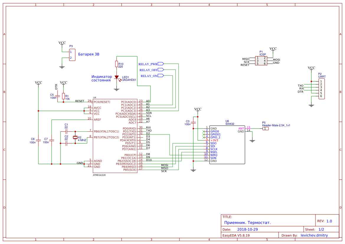
Gathering all the information received together, I drew a diagram of both devices:
Transmitter
Receiver
Having finished with the hardware of the project, we turn to the algorithms and their software implementation.
Algorithm
Let's start with the development of a general concept of operation and an algorithm for our devices. The figure below shows the general sequence diagram for all devices involved in the process.
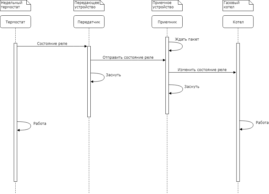
As you can see, the algorithm is not complicated, I will make its narrative presentation (well, I am too lazy to draw a flowchart, forgive me). Let's start with the transmitter, because it is the simplest in terms of the algorithm. The transmitter microcontroller performs the following sequence:
- checks the state of charge of the batteries, if the charge is low, we indicate a discharge by the built-in LED.
- polls the status of the input.
- transmits this state over the air.
- puts the transmitter into sleep mode and falls asleep for 1 minute.
- the cycle repeats from the beginning.
With the receiver, everything is a little more complicated. The microcontroller works according to the following algorithm:
- checks the state of charge of the batteries, if the charge is low, we indicate a discharge by the built-in LED.
- we wait for the packet from the transmitter, if within 2 minutes the signal is not received, we fall asleep for 59 seconds, after which the cycle starts from the beginning.
- if the package came, we get a new state of the relay.
- if the new state of the relay is different from the previously saved state, then turn on the boost converter and switch the relay to the desired state.
- fall asleep for 59 seconds
- repeat the cycle again
Thus, when the receiver is first turned on, it waits for the signal from the transmitter, as soon as it receives it, it makes a change to the relay state and falls asleep by 1 second less than the transmitter. As a result, at the time of the new parcel, the receiver is already in service and is awaiting a new parcel, i.e. It is as if synchronized by the transmitter. As a result, it was possible to save energy well. If the signal from the transmitter is not received, then we are waiting for a maximum of 2 minutes, this interval is chosen to ensure that the signal is caught regardless of the time the transmitter is turned on. But it is extremely uneconomical and is provided solely for device synchronization.
Lifetime
When it became clear with the algorithm, we will try to calculate the battery life.
Let us turn a little to the theory necessary to obtain exact figures when calculating the sensor operation time from a set of batteries.
So, at first we will consider, when and on what the electric power is spent.
Let us consider in more detail the procedure for sending.
To transmit the state of the relay, we need to create a packet and send it on the air. In general, the structure of such a package is as follows:
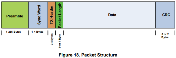
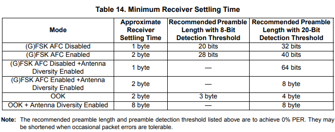
I used the default parameters of the transmitter, i.e. FSK, No Manchester, Rb = 2.4kbs, Fd = 36kHz. The amount of data transmitted in the packet is 3 bytes. The preamble size will be 40 bits based on the table:
In order not to go deep into the wilds of the module settings and the work of the library, we will take the other parameters as the maximum allowed. As a result, we get the total packet size of 5 bytes + 4 bytes + 4 bytes + 1 byte + 3 bytes + 2 bytes = 19 bytes, i.e. 152 bits. With a speed of 2400 bps, the transmission time is approximately 64 ms.
Let us turn to the table of energy consumption by the module at the beginning of the article and take from there the current value when transmitting with an output power of 13 dBm. Thus, when sending data, the module spends 30 mA.
In receive mode, the module will statically consume 18.5 mA based on the same table.
I did not manage to transfer the module to Shutdown mode, for some reason I could not remove it from the coma, as a result I limited myself to the Sleep mode at which the module consumes 1 uA.
Also at the time of receiving and transmitting the packet, I turn on the red LED connected through a 1 kΩ resistor to 3.3 volts, it consumes about 1 mA.
The microcontroller in wake mode consumes 2.4 mA, and in sleep mode with WDT enabled - 44 uA. Data obtained from the table above.
The receiver also has a parasitic leakage current when the thermostat contact is closed through the pull-up resistor to the ground (see the transmitter circuit), thus 3.3 V / 10 kΩ = 33 uA flow through it. This seemed to me a large value, so in the circuit I changed the resistor nominal by 100 kΩ, but in the hardware it was still assembled with 10 kΩ, so we’ll really consider it as it is.
The receiver has more consumers. First, it is a 20 volt boost converter. In sleep mode, it consumes 1 uA. In idle mode, the consumption will be 2.2 mA, in the program I'm waiting for 100 ms to start the converter. As a load we have a relay coil, its characteristics are listed below:

Thus, it turns out that a coil with a power supply of 20 volts will consume 20 V / 1920 Ohm = 11 mA. Now we turn to the graph of the dependence of efficiency on the current consumed by the load to estimate the total consumption of the converter with the relay coil connected.
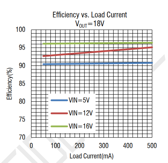
As we see, with such consumption, the schedule does not reflect the efficiency, but suppose that it also moves linearly downwards, and even in the worst case, the efficiency will be approximately 85%. As a result, the current consumption will be 11 mA / 0.85 = 13 mA. We have to admit that in fact, the peak current at the start of the converter will be at least 1A, and the work and start processes are complex, and I am not the person who can correctly state them, so I will miss them and simplify the process a bit.
The time of the impulse formed by the switching of the relay is 20 ms.
Now that we have figured out who consumes energy and how much, let's calculate the theoretical lifetime of AA batteries. Again, consider the receiver and transmitter separately.
Let's start as always with the transmitter. Let's take as a basis the algorithm of work given above. The wakefulness time of the controller will be a little longer than the transmission time and taking into account the cost of setting up the module, the input voltage and battery voltage metering will be 70 ms, then the controller will be put to sleep for one minute. Thus, for one cycle of operation, the controller will consume 0.07 s * (30 mA transmitter + 1 mA LED + 2.4 mA MK) + 60 s * (44 uA MK + 1 uA transmitter + 33 uA input resistor) = 2.338 mA * s + 4.68 mA * s = 7.018 mA * s. Dividing the obtained value by 60.07 s, we obtain the average current value per second - 0.117 mA. The average capacity of one AA-size battery is 2800 mA * h (if connected in series, the total capacity of the batteries does not increase, if someone does not know) - this is 2800 * 3600 = 10080000 mA * s. As a result, the theoretical operating time of the transmitter from one set of batteries is 100,80000 mA * s / 0.117 mA / 3600 s / 24 h = 997 days.
Now about the receiver. Let us also take as a basis the algorithm of work given above, but with one reservation, we turned on both the receiver and the transmitter almost simultaneously, and, therefore, the receiver was immediately synchronized with the transmitter.
For it, the maximum wakefulness time of the controller will be the sum of the packet waiting time (it will also include reception, since the module interrupt is generated only after the packet is fully received), removing it from the module, starting the converter and setting the new relay state, and measuring battery voltage. Summing up all the data, we get 1.126 seconds, then the controller will be put to sleep for 59 seconds. But since the work cycle is more complicated than in the receiver, the calculation will consist of a larger number of states. For one cycle of operation, the controller will consume 1.006 s * (18.5 mA receiver + 2.4 mA MK) + 0.1 * (0.1 s * (18.5 mA receiver + 1 mA LED + 2.4 mA MK + 2.2 mA converter for XX) + 0.02 s * (18.5 mA receiver + 1 mA LED + 2.4 mA MK + 13 mA converter)) + 59 s * (44 uA MK + 1 uA receiver + 1 uA converter) = 21.0254 mA + 0.1 * (2.41 mA + 0.698 mA) + 2.714 mA = 24.0502 mA * s. The coefficient 0.1 reflects the fact that we only switch the relay in one of 10 cycles. Dividing the obtained value by 60.126 s, we obtain the average current value per second - 0.4 mA. Let's calculate the battery runtime. As a result, the theoretical receiver operating time from one set of batteries is 10080000 mA * s / 0.4 mA / 3600 s / 24 h = 291 days, provided that we change the state of the relay every 10 minutes.
It is obvious that in these calculations all times more than two years are not realized due to the chemical characteristics of the device battery. AA batteries are not able to work for more than two years with a constant power supply of the device, even an insignificant current, despite the fact that the capacity should be enough. But everything that is less than two years old will already become a limitation on capacity. Unfortunately, the results of the calculation for the period of the receiver's work do not fully fit into the TZ, but in this situation I made myself a break.
Implementation in code
Honestly, I am skeptical about the Arduino and its similar IDE. I began to understand the programming of microcontrollers in C and work with registers is more understandable and predictable for me than the veiled calls of high-level functions. Although on the whole the platform itself has studied some small projects I still do in it. So this time too laziness got the better of me. I was bribed by the availability of a ready-made library for SI4432 modules under the Arduino and did not really want to spend time trying to port it to CVAVR. And the rest of the code is extremely simple. Having spent several nights studying the libraries for working with the module, as well as the microcontroller's sleep mode, the first versions of the receiver and transmitter sketches were ready pretty quickly. Next, it was necessary to assemble the hardware and continue the development with real hardware.
It's alive…
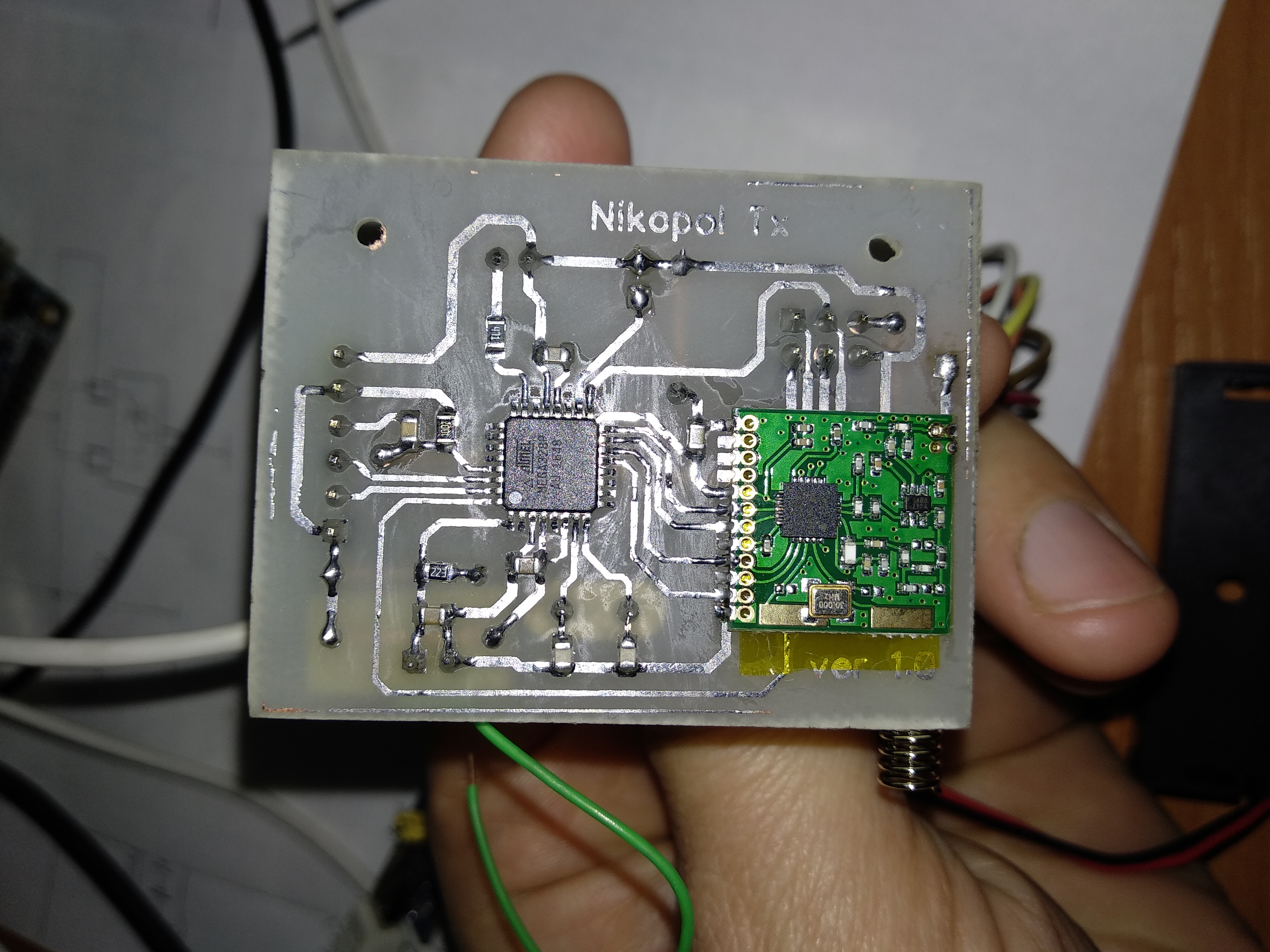
In the online service EasyEDA, a project was developed with a circuit and printed circuit boards. I didn’t bother with double-sided cards, so I put jumpers on the back side.
Here are photos of the finished transmitter boards ...
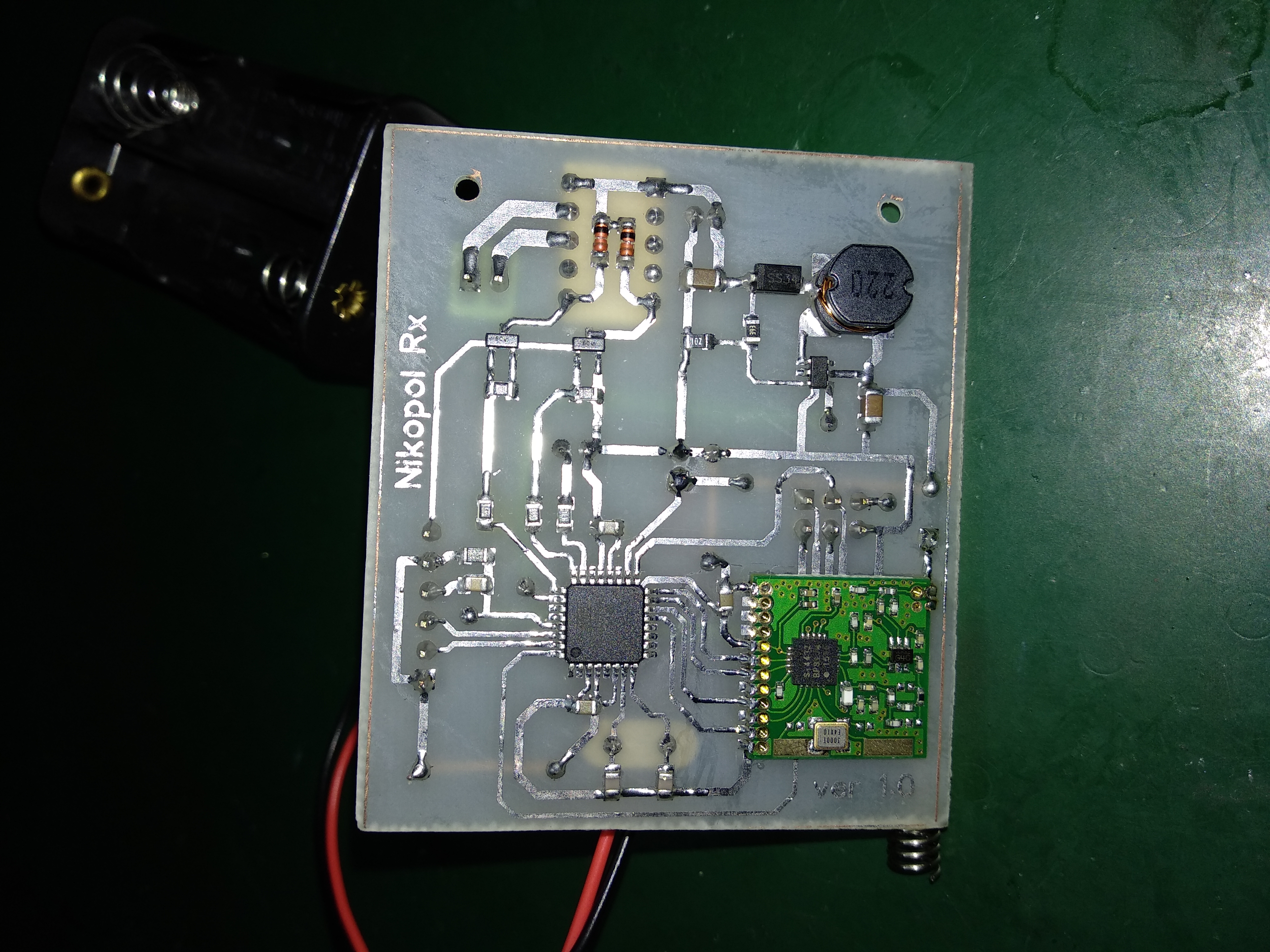
... and receiver.
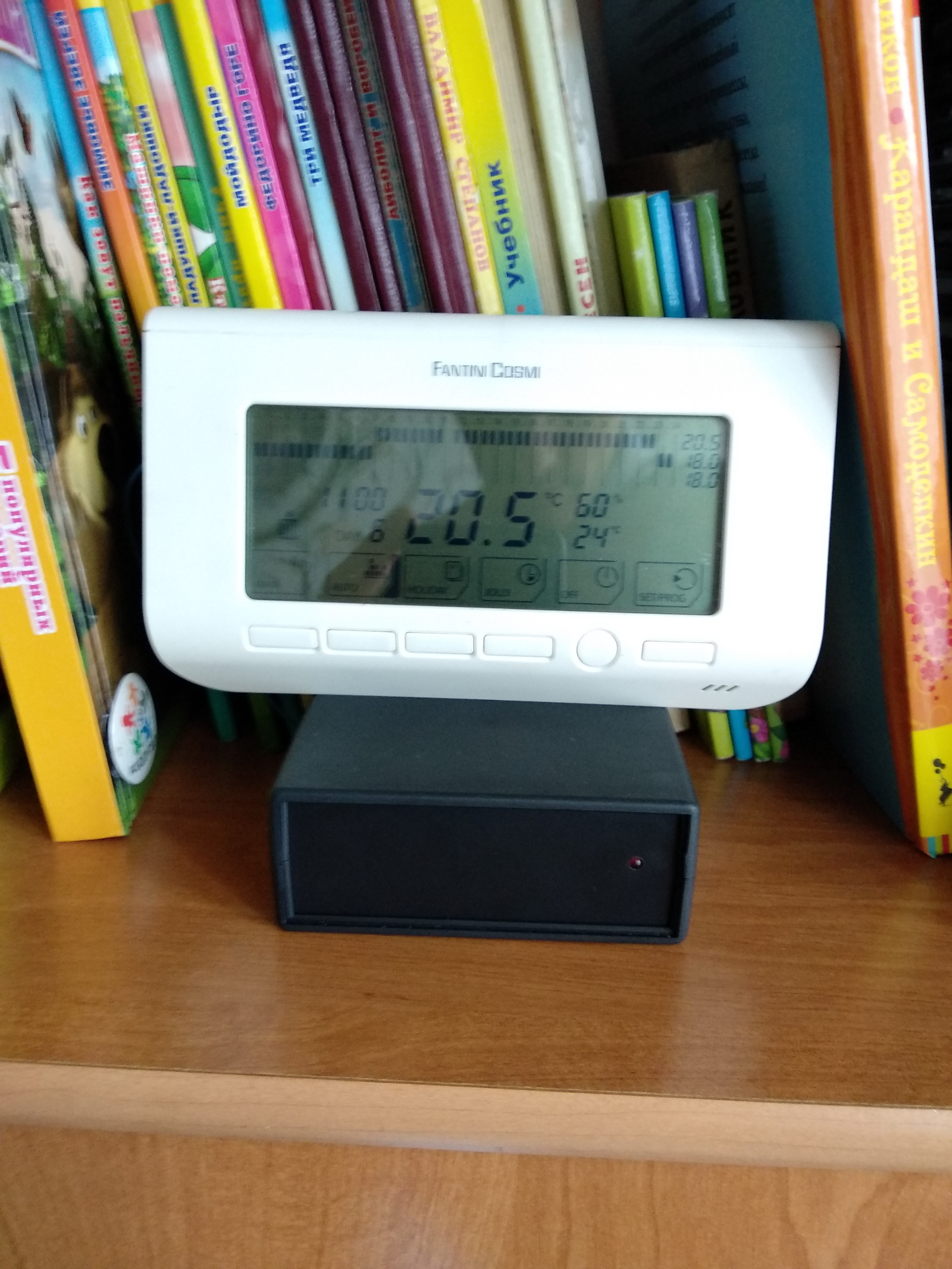
For the battery purchased holders, and also bought the case. Honestly, I wanted white, but we didn’t have such, so I had to collect in black.
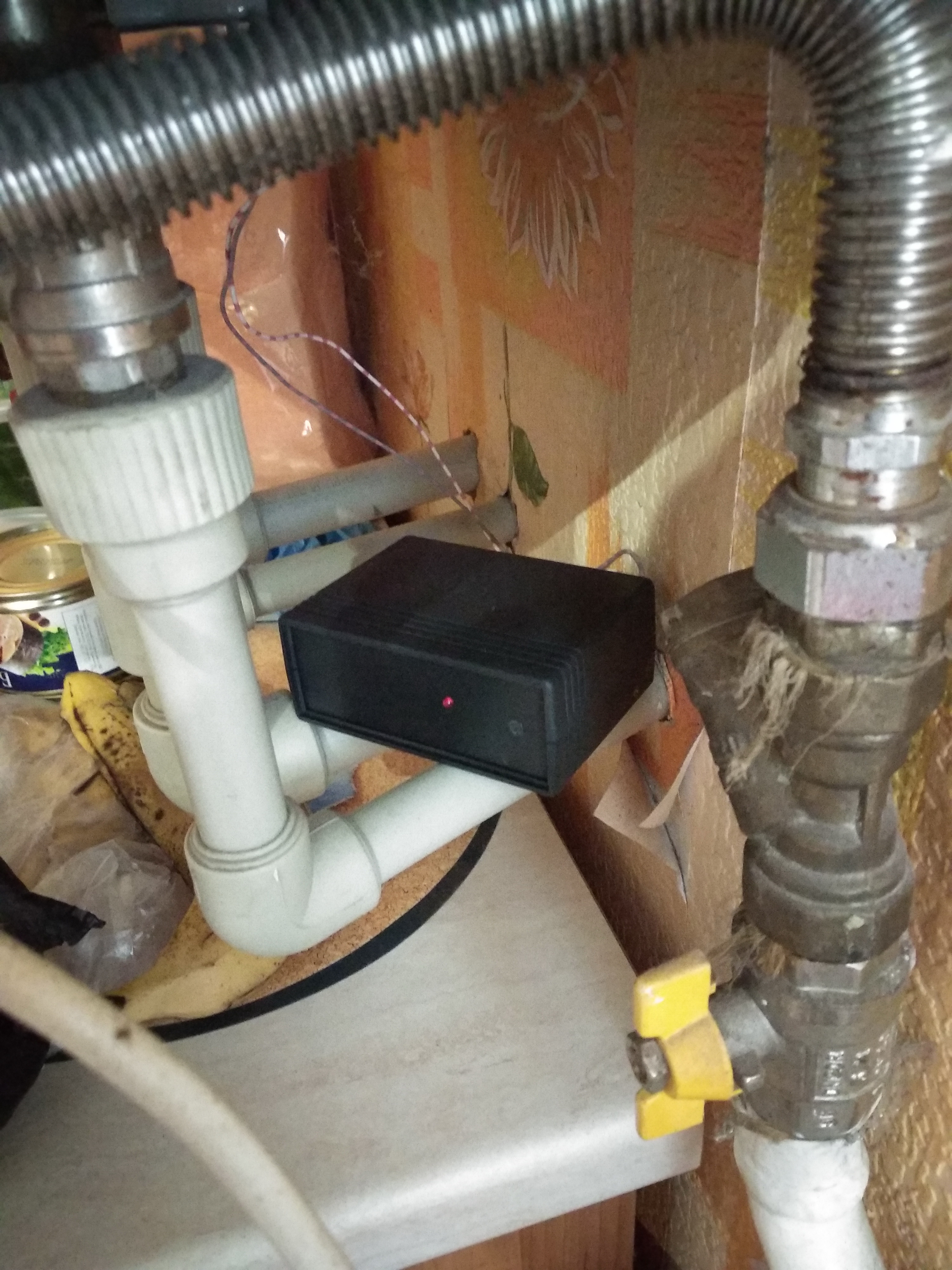
The assembly of boards was first performed without modules, since You need to fill the controller with the programmer first. And since the module is 3.3 volts and the programmer is 5 volts and they use the same bus, it is better to solder the module after the firmware. I checked the power, programmed the bootloader. In view of the fact that the solder mask is not on the board, I pasted a piece of Kapton under the modules. Soldered the modules and started debugging the firmware. Immediately stepped on a rake in the form of a module hang, everything turned out to be trite, the 3-volt stabilizer, which I used did not give the required current, after connecting the LBP to the receiver and batteries to the transmitter, everything worked steadily. In addition, I installed another electrolytic capacitor in the vicinity of the converter on the power supply circuit for its normal start. I had to finish the remaining logic described above. On regular antennas, the connection was very stable. Structurally, the receiver and the transmitter are fully enclosed in the acquired housing. The boards were fixed to the regular racks with self-tapping screws to the lower part of the case, and I attached the battery holders with double-sided tape to the upper part. The case is quite tightly closed, so I did not additionally fasten it with screws, and it would be more convenient to change the batteries. As a result, a few more evenings spent on refinement and testing received the finished result.
Loader
At the expense of the loader should say a few words separately. For Arduino there are no standard loaders for quartz at 4 MHz. They need to be assembled separately, but I was lucky; in search of information, before starting the design, I came across an article by one person, he made a meteorological station on the same modules and ran into the same problems. I will leave the link to the article at the end. By the way, I recommend reading, the man also worked well. As a result, he already had a ready loader in the repository, and since it was in open access, I took advantage of it.
Conclusion
As a result, not a single evening spent was built quite working design with the necessary characteristics. Now the device has been working for more than 3 weeks, so far there are no complaints about its work, but time will tell how much my calculations were correct.
For those who say that it was possible to put the relay on 3 volts and not bother with the converter, I will answer that I completely agree with them. But for those who decide to repeat the design will be an opportunity to choose their solution. In the end - the engineer must create, and not just copy the finished design ...
Thank you all, who mastered this article until the end, I hope it was interesting. For all your questions, suggestions and comments please in the comments.
References:
Source: https://habr.com/ru/post/431272/
All Articles